
Related Manuals for Kenwood CS-1065


Summary of Contents for Kenwood CS-1065
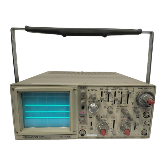
- Page 1 60MHz TRIPLE TRACE OSCILLOSCOPE C S - 1 0 6 5 40MHz TRIPLE TRACE OSCILLOSCOPE C S - 1 0 4 5 INSTRUCTION MANUAL...
-
Page 2: Table Of Contents
SAFETY Symbol in T h i s Manual Use the Proper Fuse This symbol indicates where applicable cautionary or To avoid fire hazard, use a fuse of the correct type. other information is to be found. Do not Operate in Explosive Atmospheres Power Source To avoid explosion, do not operate this product in an ex- This equipment operates from a power source that does... -
Page 3: Features
FEATURES 9. By S C A L E ILLUM control, the waveform is easy 1. Vertical axis has high sensitivity and wide bandwidth observed in darkened area and the photograph of the especially covers fully specified frequency waveform is easy provided a single photograph of the response at 5mV/div for all models. -
Page 4: Specifications
SPECIFICATIONS C S - 1 0 6 5 C S - 1 0 4 5 C R T 150TTM31 150TTM31 Rectangular, with internal graticule Rectangular, with internal graticule Acceleration Voltage 12 kV Display Area 8 x 10 div (1 div = 10 mm) V E R T I C A L A X I S CH1 and C H 2 Sensitivity... - Page 5 CS-1065 C S - 1 0 4 5 Input Impedance Same as vertical axis (CH2) DC; DC to 1 MHz, - 3 dB Frequency Response A C ; 5 Hz to 1 MHz, - 3 dB 3 ° or less at 100 kHz...
-
Page 6: P R E P A R A T I O N F O B U S E
C S - 1 0 6 5 C S - 1 0 4 5 CALIBRATION V O L T A G E 1 V ± 3 % , square wave, positive polarity, approx. 1 kHz I N T E N S I T Y M O D U L A T I O N + 5 V. - Page 7 PREPARATION FOR USE 5. Always use the probe ground clips for best results. Do S A F E T Y not use an external ground wire in lieu of the probe Before connecting the instrument to the power source, ground clips, as undesired signals may be introduced. carefully read the following information, then verify that 6.
- Page 8 Factory installed Plug configuration Power cord and plug type Line cord plug fuse instrument fuse North American 1 A , 2 5 0 V 120 volt/60 Hz Fast blow None Rated 15 amp 6 x 3 0 mm (12 amp max; NEC) Universal Europe 0 .
-
Page 9: Controls And Indicators
CONTROLS AND INDICATORS Fig. 2 AC-GND-DC F R O N T P A N E L Three-position lever switch which operates as follows: • POSITION/PULL CHOP A C : Blocks dc component of channel 1 input signal. • POSITION: Rotation adjusts vertical position of GND: Opens signal path and grounds input to vertical... - Page 10 Fig. 3 INPUT J a c k PILOT Lamp Vertical input for channel 2 trace in normal sweep opera- Lights when oscilloscope is turned on. tion. External horizontal input in X - Y operation. (Q) X GND terminal/binding post. (B> T POSITION/PULL INV Earth and chassis ground.
- Page 11 CH3 T POSITION (§) @> CH3 or E X T . TRIG Adjusts the vertical position of channel 3 trace. This con- Input terminal of channel 3 signal or external trigger signal. When vertical MODE is set at TRI, not only channel 1 and trol is used when the vertical MODE is selected to TRIPLE.
- Page 12 Fig. 4 B T R I G MODE A SWEEP TIME/DIV Used to select delay sweep mode. Horizontal coarse A sweep time selector. Selects calibrated sweep times of 0 . 0 5 /ts/div to 0.5 s/div AFTER DELAY: in 22 steps for C S - 1 0 6 5 (0.1 /ts/div to 0.5 s/div in 21 B sweep is triggered immediately after the delay set by A SWEEP TIME/DIV and DELAY steps for C S - 1 0 4 5 ) when SWEEP VARIABLE control (§) is...
-
Page 13: R E A R Panel
® POSITION @> HOLDOFF Adjusts holdoff (trigger inhibit period beyond sweep dura- Rotation adjusts horizontal position of trace. tion). Clockwise rotation from the NORM position in- creases holdoff time, up to 10 times at the MAX. position (§) FINE/PULL X 1 0 MAG control (fully counterclockwise). -
Page 14: O P E R A T I O
OPERATION INITIAL STARTING PROCEDURE trace on the C R T in preparation for waveform observation. When using the probe(s), refer to probe's instructions and Until you familiarize yourself with the use of all controls, "PROBE COMPENSATION" listed in "APPLICATION" of the following procedure may be used to standarize the in- this manual. - Page 15 Internal Sync Trigger signal When the SOURCE selection is in INT (V.MODE, C H 1 , (Gate signal) CH2, LINE), the input signal is connected to the internal trigger circuit. In this position, a part of the input signal fed to the INPUT (5) or (9) jack is applied from the vertical C H 1 (Input signal t o amplifier to the trigger circuit to cause the trigger signal...
- Page 16 Triggering Level Trigger point on waveform is adjusted by the LEVEL/PULL control. Fig. 9 shows the relationship between the SLOPE and LEVEL of the trigger point. Triggering level can Trigger point be adjusted as necessary. " N O R M " S L O P E "...
-
Page 17: Magnified Sweep Operation
(2) M A G N I F I E D S W E E P O P E R A T I O N B S w e e p Since merely shortening the sweep time to magnify a por- tion of an observed waveform can result in the desired por- tion disappearing off the screen, such magnified display should be performed using the MAGNIFIED SWEEP. -
Page 18: Video Signal Observation
15! V I D E O S I G N A L O B S E R V A T I O N Procedure: 1. Set the A TRIG MODE (§) to either AUTO or NORM. The T V FRAME/LINE switch permits selection of vertical or Apply a signal of approximately the same amplitude and horizontal sync pulse for sweep triggering when viewing frequency as the signal that is to be observed as the trig-... -
Page 19: Application
APPLICATIONS 2. Set the A TRIG MODE to AUTO and AC-GND-DC to the PROBE ADJUSTMENT GND position, which established the zero volt reference. To obtain an accurate measurement result, the probe must Using the • POSITION control, adjust the trace position be adjusted correctly before measurement. -
Page 20: Elimination Of Undesired Signal Components
M E A S U R E M E N T O F T H E V O L T A G E BETWEEN T W O ELIMINATION OF UNDESIRED SIGNAL POINTS ON A WAVEFORM COMPONENTS This technique can be used to measure peak-to-peak The ADD feature can be conveniently used to cancel out voltages. -
Page 21: Time Measurements
[EXAMPLE] For the example, the horizontal distance between the two points is 5.4 divisions. If the SWEEP TIME/DIV is 0.2 ms/div we calculate. (See Fig. 19) Substituting the given value: Time = 5.4 (div) x 0.2 (ms) = 1.08 ms FREQUENCY MEASUREMENTS Frequency measurements are made by measuring the... -
Page 22: Pulse Width Measurements
2. Count the number of cycles of waveform between a Adjust to the vertical scale with POSITION chosen set of vertical graduation lines. Using the horizontal distance between the vertical lines used above and the SWEEP TIME/DIV, the time span may be calculated. -
Page 23: Time Difference Measurements 2
[EXAMPLE] Adjust t o the vertical scale w i t h o POSITION For the example, the measured D is 1.8 divisions while D is 2.2 divisions. If SWEEP TIME/DIV is 2 /is we use the following relationship. (See Fig. 24) Substituting the given value: Risetime = (1.8 + 2.2) (div)x2 (/ts) = 8/ts TIME DIFFERENCE... -
Page 24: Phase Difference Measurements 2
P H A S E D I F F E R E N C E M E A S U R E M E N T S Phase difference = Horizontal distance of new sweep range (div)x45°/div This procedure is useful in measuring the phase difference of signals of the same frequency. - Page 25 2. The vertical calibration coefficient is now the reference Substituting the given value: signal's amplitude (in volts) divided by the product of ,,. . 2 Vrms the vertical amplitude set in step 1 and the VOLTS/DIV Vertical coefficient = setting. 4 (div) x 1 (V) = 0.5 Using the formula:...
-
Page 26: Pulse Jitter Measurement
Unknown signal Fig. 3 0 Pulse jitter Fig. 31 [ E X A M P L E ] SWEEP TIME/DIV is 0.1 ms and apply 1.75 kHz reference SWEEP MULTIPLICATION (MAGNIFICATION) signal. Adjust the SWEEP VARIABLE so that the distance of one cycle is 5 divisions. -
Page 27: Delayed Sweep Time Measurement
Using the formula: Intensity modulation area A S w e e p Period = (2nd dial reading — 1 s t dial reading) x Delayed sweep time (A SWEEP TIME/DIV setting) B S w e e p Fig. 3 2 [ E X A M P L E ] In the example, the A SWEEP TIME is 2 fis and the B SWEEP TIME is 0.2 fis. -
Page 28: Frequency Measurements Using
[EXAMPLE] PULSE REPETITION TIME In the example, the first dial reading is 0.61 and the second Using the delayed sweep feature, reliable time measure- is 5.78 with the A SWEEP TIME/DIV setting at 2 /is. ments can be made. Substituting the appropriate values. (See Fig. 34) 1. -
Page 29: Delayed Sweep
TIME D I F F E R E N C E M E A S U R E M E N T S USING USING D E L A Y E D S W E E P F O R M E A S U R E M E N T O F RISETIMES A N D FALLTIMES DELAYED SWEEP Risetimes and falltimes are generally measured by using the... -
Page 30: Triple-Trace Applications
TRIPLE-TRACE APPLICATIONS The sensitivities of channel 1 thru channel 3 are calibrated and each channel has 60 MHz band width. (For C S - 1 0 4 5 , Main s w e e p 4 0 MHz) The trigger signal of channel 3 can be obtained from its preamplifier. - Page 31 X - Y A P P L I C A T I O N S * Phase Shift Measurement A method of phase measurement requires calculations bas- ed on the Lissajous patterns obtained using X-Y operations. Distortion due to non-linear amplification also can be Amplitude distortion, No amplitude distortion, displayed.
-
Page 32: Accessories
ACCESSORIES STANDARD A C C E S S O R I E S INCLUDED OPTIONAL A C C E S S O R I E S Probe ( P C - 3 0 ) Y 8 7 - 2 2 6 0 - 0 0 Probe Pouch (MC-78) Y 8 7 - 1 6 0 0 - 0 0 Attenuation... -
Page 33: Maintenance
MAINTENANCE REPLACING THE FUSE C H A N G I N G T H E S U P P L Y V O L T A G E In case the fuse has blown, locate the cause. If the fuse Remove the fuse holder in the rear panel using a standard itself is the cause, replace it as follows: screwdriver. - Page 34 MEMO...
- Page 35 A product of K E N W O O D CORPORATION 17-5, 2-chome, Shibuya, Shibuya-ku, Tokyo 150, Japan © PRINTED IN J A P A N B 5 0 - 7 5 8 8 - 3 0 (T) 8 9 / 1 2 1 1 1 0 9 8 7 6 5 4 3 2 1 8 8 / 1 2 1 1 1 0 9 8...