
Related Manuals for GE GEP5.0-3-10


Summary of Contents for GE GEP5.0-3-10
- Page 1 4-20kW Three Phase User Manual V1.0 Grid-Tied PV Inverter www.gesolarinverter.com...
- Page 2 Content User Manual V1.0-2022-05-10 Trademarks and other GE trademarks are trademarks of General Electric Company. All other trademarks or registered trademarks mentioned in this manual are owned by General Electric Company. Notice The information in this user manual is subject to change due to product updates or other reasons.
-
Page 3: Table Of Contents
Content User Manual V1.0-2022-05-10 CONTENT 1 About This Manual ���������������������������������������������������������IV 1.1 Applicable Model ..................IV 1.2 Target Audience ..................IV 1.3 Symbol Definition ..................IV 1.4 Updates ..................... 1 2 Safety Precaution �����������������������������������������������������������2 2.1 General Safety................... 2 2.2 DC Side ...................... 2 2.3 AC Side ...................... - Page 4 Content User Manual V1.0-2022-05-10 6 Electrical Connection ���������������������������������������������������� 16 6.1 Safety Precautions ................. 16 6.2 Connecting the PE Cable ................ 16 6.3 Connecting the PV Input Cable .............. 17 6.4 Connecting the AC Output Cable ............25 6.5 Communication ..................27 6.5.1 Connecting the Communication Cable (optional) .........
-
Page 5: About This Manual
1�1 Applicable Model This manual applies to the listed inverters below (GEP for short): Model Nominal Output Power Nominal Output Voltage GEP4.0-3-10 GEP5.0-3-10 GEP6.0-3-10 GEP8.0-3-10 3/N/PE, 220/380Vac GEP10-3-10 10kW 3/N/PE, 230/400Vac GEP12-3-10... -
Page 6: Updates
01 About This Manual User Manual V1.0-2022-05-10 1�4 Updates The latest document contains all the updates made in earlier issues. V1�0 2021-7-30 • First Issue... -
Page 7: Safety Precaution
02 Safety Precaution User Manual V1.0-2022-05-10 2 Safety Precaution Notice The inverters are designed and tested strictly complies with related safety rules. Read and follow all the safety instructions and cautions before any operations. Improper operation might cause personal injury or property damage as the inverters are electrical equipment. 2�1 General Safety Notice •... -
Page 8: Ac Side
02 Safety Precaution User Manual V1.0-2022-05-10 2�3 AC Side WARNING The voltage and frequency at the connecting point should meet the on-grid requirements. An additional protective device like the circuit breaker or fuse is recommended on the AC side. Specification of the protective device should be at least 1.25 times the AC output rated current. PE cable of the inverter must be connected firmly. -
Page 9: Product Introduction
PV String Circuit Power Utility Inverter Meter Breaker Grid 3�2 Circuit Diagram The circuit diagram of GEP4.0-3-10, GEP5.0-3-10, GEP6.0-3-10, GEP8.0-3-10, and GEP10-3-10 is as follows. DC Switch PV1+ MPPT1 Filter DC/AC PV1- Inverter Filter Filter... -
Page 10: Supported Grid Types
03 Product Introduction User Manual V1.0-2022-05-10 3�3 Supported Grid Types For the grid type with neutral wire, the N to ground voltage must be less than 10V. TN-S TN-C TN-C-S Inverter Inverter Inverter Inverter Inverter... -
Page 11: Appearance
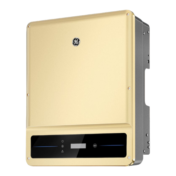
03 Product Introduction User Manual V1.0-2022-05-10 3�4 Appearance 3�4�1 Appearance GEP4.0-3-10, GEP5.0-3-10, GEP6.0-3-10, GEP12-3-10, GEP15-3-10, GEP20-3-10 GEP8.0-3-10, GEP8-3-AU10, GEP10-3-10, GEP10-3-AU10... - Page 12 03 Product Introduction User Manual V1.0-2022-05-10 No� Parts Description LED Indicator Indicates working state of the inverter. Optional. Used to check the parameters of the inverter. Optional. Used to control contents displayed on the Button screen. Grounding Point Used to connect the PE cable. Mounting Plate Used to install the inverter.
-
Page 13: Indicators
Steady red System fault. Alarming No fault. 3�4�3 Nameplate The nameplate is for reference only. GE trademark, product type, and product model * * * * * Technical parameters Safety symbols and certification marks S/N: Contact information and serial number ********************************** Co.,Ltd. -
Page 14: Check And Storage
04 Check and Storage User Manual V1.0-2022-05-10 4 Check and Storage 4�1 Check Before Receiving Check the following items before receiving the product. 1. Check the outer packing box for damage, such as holes, cracks, deformation, and others signs of equipment damage. Do not unpack the package and contact the supplier as soon as possible if any damage is found. -
Page 15: Storage
04 Check and Storage User Manual V1.0-2022-05-10 NOTICE • The PV box and PV box mounting plate will be delivered when GEP15-3-10 or GEP20-3-10 is used in Australia only. • The number of MC4 PV connectors and the PV terminals in the inverter is the same. •... -
Page 16: Installation
05 Installation User Manual V1.0-2022-05-10 5 Installation 5�1 Installation Requirements Installation Environment Requirements 1. Do not install the equipment in a place near flammable, explosive, or corrosive materials. 2. Install the equipment on a surface that is solid enough to bear the inverter weight. 3. - Page 17 05 Installation User Manual V1.0-2022-05-10 Installation Angle Requirements • Install the inverter vertically or at a maximum back tilt of 15 degrees. • Do not install the inverter upside down, forward tilt, back forward tilt, or horizontally. Mounting Support Requirements •...
- Page 18 03 Product Introduction User Manual V1.0-2022-05-10 Installation Tool Requirements The following tools are recommended when installing the equipment. Use other auxiliary tools on site if necessary. RJ45 crimping Goggles Safety shoes Safety gloves Dust mask tool DC terminal Diagonal Hammer Wire crimping tool Heat gun...
-
Page 19: Inverter Installation
05 Installation User Manual V1.0-2022-05-10 5�2 Inverter Installation 5�2�1 Moving the Inverter CAUTION Move the inverter to the site before installation. Follow the instructions below to avoid personal injury or equipment damage. 1. Consider the weight of the equipment before moving it. Assign enough personnel to move the equipment to avoid personal injury. - Page 20 05 Installation User Manual V1.0-2022-05-10 NOTICE The PV box should be installed when GEP15-3-10 or GEP20-3-10 is used in Australia only. Install the cover of the PV box after connecting the DC input cable to the equipment. Otherwise, the DC input cable cannot be connected. 1.2~2N·m...
-
Page 21: Electrical Connection
06 Electrical Connection User Manual V1.0-2022-05-10 6 Electrical Connection 6�1 Safety Precautions DANGER • Disconnect the DC switch and the AC output switch of the inverter to power off the equipment before any electrical connections. Do not work with power on. Otherwise, an electric shock may occur. -
Page 22: Connecting The Pv Input Cable
06 Electrical Connection User Manual V1.0-2022-05-10 L=L1+(1~2)mm 1.2~2N·m 6�3 Connecting the PV Input Cable DANGER Confirm the following information before connecting the PV string to the inverter. Otherwise, the inverter may be damaged permanently or even cause fire and cause personal and property losses. 1. - Page 23 06 Electrical Connection User Manual V1.0-2022-05-10 Click NOTICE Seal the PV input terminals using waterproof covers when they are not to be used. Otherwise, the ingress protection rating will be influenced. Connecting the DC Input Cable(with PV box) NOTICE The PV box should be installed when GEP15-3-10 or GEP20-3-10 is used in Australia only. Install the cover of the PV box after connecting the DC input cable to the equipment.
- Page 24 06 Electrical Connection User Manual V1.0-2022-05-10 Devalan DC Connector 7~8mm 7~8mm 2.5mm ≤ S ≤ 4mm...
- Page 25 06 Electrical Connection User Manual V1.0-2022-05-10 Use a multimeter to measure the DC voltage and check the polarity of the connectors. Click Click...
- Page 26 06 Electrical Connection User Manual V1.0-2022-05-10 Staubli MC4 DC Connector 7~8mm 7~8mm ≤ S ≤ 6mm...
- Page 27 06 Electrical Connection User Manual V1.0-2022-05-10 Use a multimeter to measure the DC voltage and check the polarity of the connectors. Click Click...
- Page 28 06 Electrical Connection User Manual V1.0-2022-05-10 Connecting the DC Input Cable (without PV box) Step 1 Prepare DC cables. Step 2 Crimp the crimp contacts. Step 3 Disassemble the PV connectors. Step 4 Make the DC cable and detect the DC input voltage. Step 5 Plug the PV connectors into the PV terminals.
- Page 29 06 Electrical Connection User Manual V1.0-2022-05-10 Staubli MC4 DC Connector 7~8mm 7~8mm ≤ S ≤ 6mm Use a multimeter to measure the DC voltage and check the polarity of the connectors. Click Click...
-
Page 30: Connecting The Ac Output Cable
06 Electrical Connection User Manual V1.0-2022-05-10 6�4 Connecting the AC Output Cable WARNING • Do not connect loads between the inverter and the AC switch directly connected to it. • Where an external RCD (Residual Current Device) is required in addition to the built-in RCMU (Residual Current Monitoring Unit), and a type A RCD must be used to avoid tripping,... - Page 31 06 Electrical Connection User Manual V1.0-2022-05-10 Step 1 Make the AC output cable. Step 2 Disassemble the AC cover. Step 3 Crimp the AC cable OT terminal and route the cable into the AC cover. Step 4 Fasten the AC output cable and secure the AC cover. L=L1+(1-2)mm L2 L3 1.2~2N·m...
-
Page 32: Communication
06 Electrical Connection User Manual V1.0-2022-05-10 6�5 Communication 6�5�1 Connecting the Communication Cable (optional) NOTICE Make sure that the communication device is connected to the right COM port. Route the communication cable far away from any interference source or power cable to prevent the signal from being influenced. - Page 33 06 Electrical Connection User Manual V1.0-2022-05-10 Power limit networking scenario (single inverter) RS485+ RS485- Smart meter Inverter Three-phase Grid Meter circuit breaker Single-phase circuit breaker Load Power limit networking scenario (multi inverters) Ethernet RS485+ SEC1000 RS485- Router Cloud Inverter N Inverter 1 Three-phase Grid...
- Page 34 06 Electrical Connection User Manual V1.0-2022-05-10 Connecting the Communication Cable(RS485, Meter, and DRED) NOTICE Connect the RS485 cable, meter cable, and DRED cable using a 6PIN communication terminal as follows. RS485/ DRED Meter 6.5mm 25mm RS485/Meter (COM2) DRED (COM3) 1: RS485 B 1: DRM1/5 0.3~0.4N·m 2: RS485 B...
- Page 35 06 Electrical Connection User Manual V1.0-2022-05-10 Connecting the Remote Shutdown (RSD) Communication Cable NOTICE Connect the remote shutdown cable using a 2PIN communication terminal as follows. RS485 6.5mm 25mm +: DRM4/8 -: REFGen 0.6~0.8N·m...
-
Page 36: Installing The Communication Module (Optional)
06 Electrical Connection User Manual V1.0-2022-05-10 6�5�2 Installing the Communication Module (optional) Plug a communication module into the inverter to establish a connection between the inverter and the smartphone or web pages. The communication module can be a Bluetooth module, WiFi module, LAN module, or 4G module. -
Page 37: Equipment Commissioning
07 Equipment Commissioning User Manual V1.0-2022-05-10 7 Equipment Commissioning 7�1 Check Items Before Switching Power ON No� Check Item The inverter is firmly installed in a clean place where is well-ventilated and easy to operate. The PE cable, DC input cable, AC output cable, and communication cable are connected correctly and securely. -
Page 38: Power On
08 System Commissioning User Manual V1.0-2022-05-10 8 System Commissioning 8�1 Indicators and Button Type Status Description Steady yellow Communication status is normal. Communication is reseting or Single yellow blinking restarting. Double yellow The inverter is not connected to the blinking router. -
Page 39: Setting Inverter Parameters Via Lcd
08 System Commissioning User Manual V1.0-2022-05-10 8�2 Setting Inverter Parameters via LCD NOTICE • Inverter software version shown in this document is V1.00.00.13. The screen shots are for reference only. The actual display may differ. • The name, range, and default value of the parameters is subject to change or adjust. The actual display prevails. - Page 40 08 System Commissioning User Manual V1.0-2022-05-10 Previous page Long press Long press for 2s Long press for 2s Long press for 2s for 2s Set Time 2000-00-00 00:00 2000-00-00 00:00 2000-00-00 00:00 ······ Pac = xxx W Short press 4G and GPRS WiFi module Set OK Wait...
-
Page 41: Inverter Parameter Introduction
08 System Commissioning User Manual V1.0-2022-05-10 Previous page Short press Short press Short press Short press Long press for 2s Set ARC Self Check ARC Enable ARC Disable Fault Clear Pac = xxx W Short press Set OK Set Fail Short press Long press for 2s USB Mode Select... - Page 42 08 System Commissioning User Manual V1.0-2022-05-10 Parameters Description Soft limit: Set the power feed into the utility grid according to local requirements and standards. Power Limit Hard limit: The inverter and the utility grid will automatically disconnect when the power feeds into the grid excesses the required limit.
-
Page 43: Setting Inverter Parameters Via App
08 System Commissioning User Manual V1.0-2022-05-10 8�3 Setting Inverter Parameters via App SolarGo is an application used to communicate with the inverter via Bluetooth module, WiFi module, or GPRS module. Commonly used functions: 1. Check the operating data, software version, alarms of the inverter, etc. 2. -
Page 44: Maintenance
09 Maintenance User Manual V1.0-2022-05-10 9 Maintenance 9�1 Power Off the Inverter DANGER • Power off the inverter before operations and maintenance. Otherwise, the inverter may be damaged or electric shocks may occur. • Delayed discharge. Wait until the components are discharged after power off. Step 1 (optional) Send shutdown command to the inverter, Step 2 Turn off the AC switch between the inverter and the utility grid. -
Page 45: Troubleshooting
09 Maintenance User Manual V1.0-2022-05-10 9�4 Troubleshooting Perform troubleshooting according to the following methods. Contact the after-sales service if these methods do not work. Collect the information below before contacting the after-sales service, so tha the problems can be solved quickly. 1. - Page 46 09 Maintenance User Manual V1.0-2022-05-10 No� Fault Cause Solutions 1. Check whether the PV input cables are broken. 1. The PV system is 2. Check whether the module frames and the metal short-circuited bracket are securely grounded. to the ground. 3.
- Page 47 09 Maintenance User Manual V1.0-2022-05-10 No� Fault Cause Solutions A fault occurs in all AFan Fail 1. Restart the inverter and check whether the fans of the inverter. inverter can work normally. A fault occurs on 2. Make sure that the fans are working properly and EFan Fail the external fan of not covered or blocked.
-
Page 48: Routine Maintenance
09 Maintenance User Manual V1.0-2022-05-10 9�5 Routine Maintenance Maintaining Item Maintaining Method Maintaining Period Check the heat sink, air intake, and air System Clean Once 6-12 months outlet for foreign matter or dust. Check the fan for proper working status, Once a year low noise, and intact appearance. -
Page 49: Technical Parameters
10 Technical Parameters User Manual V1.0-2022-05-10 10 Technical Parameters Technical Data GEP4.0 -3 -10 GEP5.0 -3 -10 GEP6.0 -3 -10 GEP8.0 -3 -10 GEP8-3-AU10 Input Max. Input Power (W) 8,000 10,000 12,000 16,000 16,000 Max. Input Voltage (V) 1100 1100 1100 1100 1100... - Page 50 10 Technical Parameters User Manual V1.0-2022-05-10 Technical Data GEP4.0 -3 -10 GEP5.0 -3 -10 GEP6.0 -3 -10 GEP8.0 -3 -10 GEP8-3-AU10 AC Grid Frequency Range 45~55 / 45~55 / 45~55 / 55~65 45~55 / 55~65 45~55 / 55~65 (Hz) 55~65 55~65 Max.
- Page 51 10 Technical Parameters User Manual V1.0-2022-05-10 Technical Data GEP4.0 -3 -10 GEP5.0 -3 -10 GEP6.0 -3 -10 GEP8.0 -3 -10 GEP8-3-AU10 Emergency Power Off Optional Remote Shutdown Optional General Data Operating Temperature -30~+60 Range (℃) Relative Humidity 0~100% Max. Operating Altitude 4000 Cooling Method Natural Convection...
- Page 52 10 Technical Parameters User Manual V1.0-2022-05-10 Technical Data GEP10-3-10 GEP10-3-AU10 GEP12-3-10 GEP15-3-10 GEP20-3-10 Input Max. Input Power (W) 20,000 20,000 24,000 30,000 40,000 Max. Input Voltage (V) 1100 1100 1100 1100 1100 MPPT Operating Voltage 140~950 140~950 140~950 140~950 140~950 Range (V) MPPT Voltage Range at 360~850...
- Page 53 10 Technical Parameters User Manual V1.0-2022-05-10 Technical Data GEP10-3-10 GEP10-3-AU10 GEP12-3-10 GEP15-3-10 GEP20-3-10 AC Grid Frequency Range 45~55 / 45~55 / 45~55 / 55~65 45~55 / 55~65 45~55 / 55~65 (Hz) 55~65 55~65 Max. Output Current (A) 16.0 16.0 19.1 24.0 32.0 Max.
- Page 54 10 Technical Parameters User Manual V1.0-2022-05-10 Technical Data GEP10-3-10 GEP10-3-AU10 GEP12-3-10 GEP15-3-10 GEP20-3-10 Emergency Power Off Optional Remote Shutdown Optional General Data Operating Temperature -30~+60 Range (℃) Relative Humidity 0~100% Max. Operating Altitude 4000 Cooling Method Natural Convection User Interface LED, LCD (Optional),...
- Page 55 Global Sales & Service Network * GE is a registered trademark of General Electric Company and is used under license by GoodWe Technologies Co., Ltd. © 2022 All Rights Reserved No.90 Zijin Rd., New District, Suzhou, 215011, China www.gesolarinverter.com Local Contacts...