Table of Contents
Advertisement
Quick Links
Advertisement
Table of Contents

Related Manuals for Logitech 2000 MKIII Series


Summary of Contents for Logitech 2000 MKIII Series
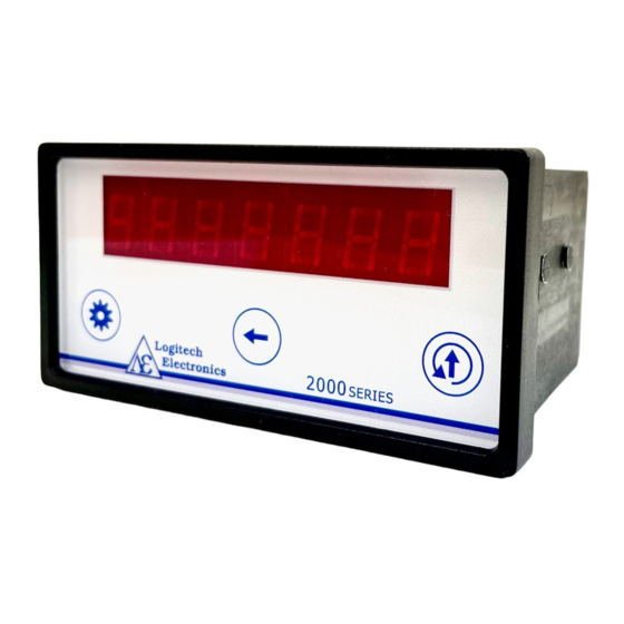
- Page 1 2000 MKIII SERIES Tachometers Model 2000T/DC User Guide...
-
Page 2: Specification
Specification Display 7 decade (or 6 decade and sign), 7-segment high brightness red LED, 10mm high Decimal point Programmable via display Scaling Programmable via display, retained in non-volatile memory Signal inputs Protected to 100Vdc Standard sensitivity mode From 90mV @ 10Hz, 170mV @ 10kHz High sensitivity mode From 12mV @ 10Hz, 20mV @ 10kHz Frequency... -
Page 3: General Description
2000T are available with factory fitted options, which must be specified when MKIII SERIES ordering. Additionally, Logitech will customise the programmed operating modes of these tachometers to suit specialised applications. Please contact our sales office to discuss this. 2000T Variants... -
Page 4: Front Panel
Front Panel The panel has three touch switches: settings, select and increment/reset. Settings Increment/reset Select Rear panel terminals The image above shows the rear panel of a standard 2000T MKIII instrument. The actual terminals available on the rear panel will vary depending on the model. Below are the definitions of each of the terminals that may be present. - Page 5 Supply voltage, passed through from power connector, or apply 12-30Vdc to power unit). = 0V/ground passed through from power connector or connect to 0V if powering unit from rear terminals. RST = Reset input. Used to reset the latching alarms on “L” models and to release the settings lock on all 2000T models.
-
Page 6: Programming The Instrument
Programming the instrument Calculated Result The result will be calculated according to the options and values selected for the mode, calculation, scaling factor and offset, which are described in detail below. The equation for this will be as follows: CALC: Frequency A mode: Frequency B mode: �� = (��... - Page 7 unit in division mode, the K-factor can be entered as the scaling factor directly, and the display would give a readout in litres per second. Calculating a scaling factor The scaling factor is often most easily calculated by considering the maximum input frequency expected and by deciding what the display should read at this frequency.
-
Page 8: Setting An Offset
Setting an Offset The 2000T tachometer has an OFFSET facility that can be either positive or negative. It is a very useful addition to the scaling factor and can be used to display percentage difference between A and B, or show the deviation from a nominal value. For example: If the nominal frequency on Input A is 1000 Hz, by setting the scaling factor to 1 and the OFFSET to -1000, the display will show the deviation from 1000 Hz. -
Page 9: Alarm Outputs
additional time (in seconds) for which the unit will wait to receive a pulse, before setting the calculated frequency to zero. This setting is independent of the update time. The wait time can be user set anywhere between 1s and 20s. If the wait time is set to 0, the unit will not wait beyond the configured update time. -
Page 10: Output Options
The active mode can also be changed from the front panel. In run mode, press the select button. The current mode will be displayed for a period of 2s. Pressing select again while the mode is displayed, will switch to the next active mode. If no other modes are configured, the current mode will continue to be displayed. -
Page 11: Changing Settings
Changing Settings On first power up from factory settings, the unit will enter set mode. Set Mode can also be accessed after initial configuration by holding the settings button and then with this held, pressing the increment touch button ↑. In set mode press the settings button to move on to the next setting, select ←... - Page 12 INPUT – Set input mode [Default STD] Available in FREQ A or FREQ B mode and sets the input type for that channel only. The selected input type will also be applied to that channel in ratio mode. Press increment ↑...
- Page 13 OFFSET – Set the offset to be added to the scaled frequency [Default 0] Refer to page X for details on the offset. Press select ← to select digit and increment ↑ to change value. In signed mode, after cycling through all six digits, all digits will flash and the sign can be toggled by pressing increment ↑.
- Page 14 A REF – Set the reference (minimum) scaled frequency value for the analogue output. [Default 0] Enter the displayed (scaled) value, below which the analogue output will be at the minimum for the selected voltage/current range. Press select ← to select digit and increment ↑...
-
Page 15: Setting The Sensitivity
UPDATE – Set the display & analogue output update time [Default 1000MS] Press increment ↑ to select from the below options. One of these output modes must be selected in order for the rate controller to function. 100 MS = 100ms (0.1s) 250 MS = 250ms (0.25s) 500 MS... -
Page 16: Viewing The Settings
Viewing the Settings The current values of all settings can be viewed at any time in run mode. To do so, press and release the settings button . The display will show DISPSET and will then display the title and current value of each setting in order. To skip over a setting, press the settings button . The display will automatically return to run mode once all settings have been displayed. - Page 17 Variable Reluctance Magnetic Pickups Set input type (INPUT) to standard sensitivity (STD) or high sensitivity (HS) depending on target diameter and rotational speed. Connect the cable screen and one of the two wires from the magnetic pickup to the common 0V terminals (shown as the black wire below). Connect the other wire from the magnetic pickup to the input.
- Page 18 Electronic Sensors and Rotary Encoders Set input type (INPUT) to standard sensitivity (STD). The sensor/encoder can be supplied from the Vs terminal, provided that the sensor is rated to operate at this voltage. The sensor/encoder’s 0V connection should be made to any of the common 0V terminals, along with the cable screen if this is not connected to 0V at the sensor/encoder end.
- Page 19 Alarm Connections Example alarm configurations are shown below. NOTE: Switching Relays. If the relay module does not have integrated back EMF suppression, it is essential that a diode is connected across the coil as shown in the diagrams.
-
Page 20: Warranty
Tachometers carry a two-year warranty that is only valid where there is no MKIII SERIES damage caused by accident, negligence, misapplication, or repairs/modifications attempted by unauthorised personnel. The warranty only extends to the original user. Copyright © Logitech Electronics Limited 2022 Document No: 2000T-MKIII_hb v1.1 May 2022...