Advertisement
Quick Links
Überspannungsbegrenzer
Surge Suppressors
Betriebsanleitung
Vor der Installation, dem Betrieb oder der Wartung des Geräts muss diese Anleitung
gelesen und verstanden werden.
GEFAHR
!
Gefährliche Spannung.
Lebensgefahr oder schwere Verletzungsgefahr.
Vor Beginn der Arbeiten Anlage und Gerätespannung frei
schalten.
VORSICHT
Eine sichere Gerätefunktion ist nur mit zertifizierten Komponenten gewährleistet!
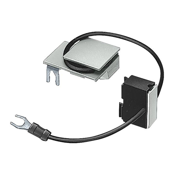
Montierter Überspannungsbegrenzer, siehe Bild 1, für Schütze 3TF40 ... 45, 3TF3, 3TH3, 3TH4
und 3TC44 zur Vermeidung von Störspannungen, die durch Schützspulen erzeugt werden.
Bauform: speziell geeignet für den Anbau an die Spulenklemme.
Einsatzbereiche
Freilaufdioden und Diodenkombinationen werden bei Gleichstrombetätigung verwendet - auf die
richtige Polung ist zu achten. Varistoren und RC-Glieder werden bei Gleich- und Wechselstrom-
betätigung bei Netzfrequenz bis 60 Hz verwendet.
Die Höhe der Spannungsbegrenzung (Schutzpegel) bei Beschaltung der Schützspule mit
Freilaufdiode, Diodenkombination, Varistor oder RC-Glied wird durch die Dimensionierung der
Bauelemente bestimmt.
- Durch Diodenbeschaltung lassen sich Überspannungen völlig vermeiden
(Verlängerung des Ausschaltverzuges).
- Durch Varistoren wird die maximale Höhe der Überspannung begrenzt.
- Durch RC-Glieder verringert sich die Steilheit des Spannungsanstieges
Operating Instructions
Read and understand these instructions before installing, operating, or
maintaining the equipment.
DANGER
!
Hazardous voltage.
Will cause death or serious injury.
Disconnect power before working on equipment.
CAUTION
Reliable functioning of the equipment is only ensured with certified
components.
Fitted surge suppressors, see Fig. 1, for contactors 3TF40 to 45, 3TF3, 3TH3, 3TH4 and 3TC44
for avoiding interference voltages produced by contactor coils. Design: Specially suitable for
attachment to coil terminal.
Applications
Freewheeling diodes and diode combinations are used for DC actuation (pay attention to correct
polarity). Varistors and RC elements are used for DC and AC actuation at system frequency
levels up to 60 Hz.
The extent of surge suppression (protection level) with the contactor coil protectively connected
up with freewheeling diode, diode combination, varistor or RC element depends on how the
components are dimensioned.
- With diode connection, surges can be completely avoided (prolongation of opening delay).
- Varistors limit the maximum surge level.
- RC elements limit the rate of voltage rise
(1)
(2)
3TX7402-3A
Diode/Diode; A
3TX7402-3D
Diodenkombination/Diode combination; A
3TX7402-3E
Suppressordiode/Suppressor diode; A
3TX7402-3G
Varistor/Varistor; A
3TX7402-3H
Varistor/Varistor; A
3TX7402-3J
Varistor/Varistor; A
3TX7402-3K
Varistor/Varistor; B
3TX7402-3L
Varistor/Varistor; B
3TX7402-3R
RC-Glied/RC element; B
3TX7402-3S
RC-Glied/RC element; B
3TX7402-3T
RC-Glied/RC element; B
3TX7402-3U
RC-Glied/RC element; B
3TX7402-3V
RC-Glied/RC element; B
NEB524476510000/RS-AA/002
3ZX1012-0TX02-1AA1
Montage
Maßbilder siehe Bild 2
a Gehäuseform A
b Gehäuseform B
Schaltbilder siehe Bild 3
Betrieb
Schutz vor Überlastung
Fremde Überspannungen, die z.B. durch Schalten induktiver oder kapazitiver Lasten an den
Überspannungsbegrenzern auftreten können, müssen durch Beschaltungsmaßnahmen in der
Anlage auf einen unkritischen Wert (Schutzpegel muss niedriger sein als der des Über-
spannungsbegrenzers) reduziert werden.
Die Frequenzabhängigkeit der RC-Glieder ist zu berücksichtigen. Bei höheren Netzfrequenzen
und in Netzen mit einem hohen Überschwingungsanteil können die RC-Glieder thermisch über-
lastet werden.
Technische Daten
siehe Tabelle
(1) Bestell-Nr.
(2) Begrenzertyp; Gehäuseform A oder B
(3) Nennbetätigungsspannung der Schützspule Us
(4) Schutzpegel
(5) Maximal zulässige Betriebsspannung der Bauelemente
(6) Verlängerung des Ausverzugs der beschalteten Schütze
(7) Spitzensperrspannung für Dioden bzw. Diodenkombinationen
Höchstzulässige Dauerbelastbarkeit wird bei der zulässigen Schalthäufigkeit der Schützspule
nicht überschritten.
Installation
Dimension drawings see Fig. 2
a Housing form A
b Housing form B
Circuit diagrams see Fig. 3
Operation
Overload protection
Interference voltage surges, which can occur at the suppressors for example when inductive or
capacitive loads are switched, must be reduced to a non-critical value by way of protective
circuitry in the system. (The protective level must be lower than that of the surge suppressor.)
The frequency dependence of the RC elements must be taken into account. At higher system
frequencies and in systems with high harmonic content, the RC elements may be subjected to
thermal overload.
Technical data
see Table
(1) Order no.
(2) Suppressor type; housing form A or B
(3) Rated control voltage of contactor coil Us
(4) Protection level
(5) Maximum permissible operating voltage of components
(6) Prolongation of OFF delay of contactors with protective circuit
(7) Peak reverse voltage for diodes/diode combinations
Maximum permissible limiting continuous withstand value is not exceeded when the contactor
coil is switched with permissible frequency.
(3)
(4)
AC V
DC V
AC V
—
24...250
1
—
24...250
13
—
24
—
24...48
24...70
150
48...127
70...150
350
127...240
150...250
650
240...400
—
1050
400...600
—
1500
24...48
24...70
150
48...127
70...150
170
127...240
150...250
350
240...400
—
1200
400...600
—
2000
Typen bei Varistoren
R- und C-Werte bei RC-Gliedern
Zulässige Umgebungstemperatur:
-25 °C ... +55 °C
Bemessungsisolationsspannung:
U
Verschmutzungsgrad
3
Types with varistors
R and C values with RC elements
Permissible ambient temperature:
-25 °C to +55 °C
Rated insulation voltage
U
Pollution degree
3
(5)
DC V
AC V
DC V
1
—
275
Faktor/Factor 6...9
13
—
275
Faktor/Factor 3...6
36
—
36
Faktor/Factor 2
150
53
77
350
140
165
650
265
275
—
440
—
—
660
—
200
53
77
vernachlässigbar/negligible
280
140
165
vernachlässigbar/negligible
400
265
275
vernachlässigbar/negligible
—
440
—
vernachlässigbar/negligible
—
660
—
vernachlässigbar/negligible
3TX7402-3.
Deutsch
= 690 V
i
English
= 690 V
i
(6)
(7)
4000 V
4000 V
36 V
2...5 ms
SIOV S07 K60
2...5 ms
SIOV S07 K150
2...5 ms
SIOV S07 K300
2...5 ms
SIOV S07 K460
2...5 ms
SIOV S07 K680
68 Ω
2,2 μF
220 Ω
0,68 μF
1 kΩ
0,15 μF
3,3 kΩ
0,033 μF
0,01 μF
6,8 kΩ
Last update: 04 April 2022
Advertisement

Related Manuals for Siemens 3TX7402-3A


Summary of Contents for Siemens 3TX7402-3A
- Page 1 - RC elements limit the rate of voltage rise AC V DC V AC V DC V AC V DC V 3TX7402-3A Diode/Diode; A — 24...250 — Faktor/Factor 6...9 4000 V 3TX7402-3D Diodenkombination/Diode combination; A —...
- Page 2 - Con varistores se limita la magnitud maxima de la sobretensión. - Con combinaciones RC se reduce la pendiente del gradiente de la tensión. AC V DC V AC V DC V AC V DC V 3TX7402-3A Diode/Diodo; A — 24...250 — Fakteur/Factor 6...9 4000 V 3TX7402-3D Bloc de diodes/Combinación de diodos A...
- Page 3 - O nível máximo de sobretensão é limitado por varistores - O pendor da ascensão de tensão é reduzido por elementos RC AC V DC V AC V DC V AC V DC V 3TX7402-3A Diodo/Diodos; A — 24...250 — Fattore/Fator 6...9 4000 V 3TX7402-3D Combinazone di diodi/Comb.
- Page 4 İzin verilen en yüksek sürekli yüklenebilirlik, kontaktör bobininin izin verilen anahtarlama - Gerilim artışının eğimi RC parçalarla azaltılır sıklığında aşılmaz. AC V DC V AC V DC V AC V DC V 3TX7402-3A Diyot; A — 24...250 — Faktör 6...9 4000 V 3TX7402-3D Diyot kombinasyonu; A —...
- Page 5 3TX7402-3J 3TX7402-3T 3TX7402-3K 3TX7402-3U 3TX7402-3L 3TX7402-3V SIEMENS AG https://support.industry.siemens.com Technical Support www.siemens.com/sirius/support https://support.industry.siemens.com/My/ww/en/requests Support Request Technische Änderungen vorbehalten. Zum späteren Gebrauch aufbewahren. 3ZX1012-0TX02-1AA1 Subject to change without prior notice. Store for use at a later date. © Siemens AG 1993...