Advertisement
Quick Links
Advertisement

Summary of Contents for LG GF-50712 Series
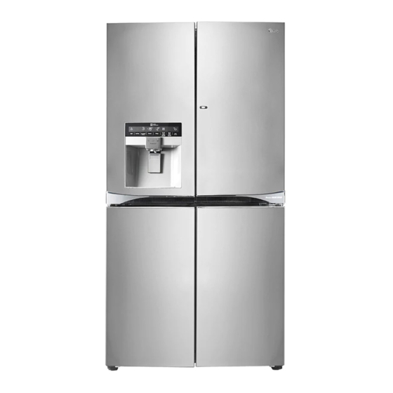
- Page 1 REFRIGERATOR SERVICE MANUAL GF-50712** GR-J24F****...
- Page 2 Table of Contents Chapter 1 Safety Warning and Cautions ..................3 Chapter 2 Product Standards ......................8 Chapter 3 Circuit Diagram .......................10 Chapter 4 Appearance Size of Refrigerator and Name of Every Part .........11 1. Appearance Size of Refrigerator ....................11 2. Major Names ..........................12 Chapter 5 Micom Function.......................13 1.
- Page 3 Safety Warning and Cautions Chapter 1 Safety Warning and Cautions 'Cautions for safety should be observed since they are for previously prevent accidents and dangers when properly use or repair products in a safe manner. Cautions are classified into Warning and Caution and meaning of them are as follows Warning Warning means symbol to inform any accidents that may result in large danger such as death or severe injury,etc when violating instructions.
- Page 4 Safety warnings and cautions Warning If grounding is required,be sure to Do not allow to store inflammable perform grounding. ether, benzene, alcohol, chemical drugs, LP gas, etc in a refrigerator. Be sure to perform grounding if deemed there is danger of There is danger of Grounding nut electric shock...
- Page 5 Safety warnings and cautions Warning Do not expand or modify length of Do not place heavy objects on a power plugs to use. refrigerator. Electric shock or fire Dropping of objects during may occur due to opening or closing doors electrical damage of may cause injury.
- Page 6 Safety warnings and cautions Caution Do put the vessel that flower Do not accumulate objects on a base,cup,cosmetics or refrigerator or do not keep drugs,etc are contained foods in random method. on the refrigerator. Dropping of objects when Fire or electric shock may occur,or opening or closing the door may cause physical injury.
- Page 7 Safety warnings and cautions Caution While you pull out the power Do not use power cords or power plugs,hold the end of the plug,not plugs when they are damaged or the cord. holes of power plugs are loose. Fire may occur due to electric shock or short-circuit.
- Page 8 Product Standard Chapter 2 Product Standard ITEM 553 L Totalval i d contents Valid Contents 188 L freezer 361 L ri d ger Icemaki n g Compartment Size 912 758 1797 Wedth(WXDX ) 143.6 kg Wei g ht 110 15%(W) motorratedcurrent 250 10% el e ctri c heatatedcurrent...
- Page 9 Product Standard freezer 4hours (Vary depending on the conditions of use) fi r stdefroster freezer 7hours ~ 50hours (Vary depending on the conditions of use) defrosterperi o d freezer 7mins breakperi o d defroster freezeer 5 (Vary depending on the conditions of use) defrostersensor component temperaturefuse...
- Page 10 Circuit Diagram Chapter 3 Circuit Diagram...
- Page 11 Appearance Size of Refrigerator and Name of Every Part Chapter 4 Appearance Size of Refrigerator and Name of Every Part 1. Appearance Size of Refrigerator (Unit : mm) Width(A) Width 1019 When opening door by 90 (including handle/button) (B) Case (including back handle) (C) After disassembling door (including hinge, L) (D) Depth Including door (not including handle) (E)
- Page 12 Appearance Size of Refrigerator and Name of Every Part *The appearance and specifications of the actual product may differ depending on the model. 2. Major Names Cover Hinge Cover PCB Back Handle Home Bar...
- Page 13 Micom Function Chapter 5 Micom Function 1. Operating panel drawing (Applied display is different for each model) Press First Press Press Press Press Press Press Press Classification 2 time 1 time 3 time 4 time 5 time power on 6 time 8 time 7 time NOTCH...
- Page 14 Micom Function 2. Function description 2-1. function of LCD/LED/Magic display panel 2-1-1. Back light control 1. When the applianc e is plugged in,it is set to 3 for Refrigerator and -18 for Freezer. You can adjust the Refrigerator and the Freezer control temperature by pressing the ADJUST button. 2.
- Page 15 Micom Function 2-1-4. Water Filter condition display function 1. 1.There is a replacement indicator light for the water In initial Power On Icon ON Classification filter cartridge on the dispenser. / Filter RESET 2. Water filter needs replacement once six months or of using water filter.
- Page 16 Micom Function 2-1-6. Hygiene Filter replacement condition display function 1. There is a replacement indicator light for the Hygiene filter cartridge . 2. Hygiene filter in OFF Mode needs replacement once 24 months. 3. Hygiene filter in Auto Mode or Power Mode needs replacement once 12 months 4.
- Page 17 Micom Function 2-2. Express freezing 1. The purpose of this function is to intensify the cooling speed of freezer and to increase the amount of ice. 2. Whenever selection switch is pressed, selection/release, the Icon will turn ON or OFF. 3.
- Page 18 Micom Function 2-6. Door opening information 1. Buzzer generates alarm sound if doors are not closed even when more than a minute consecutively has passed with doors of freezing / cold storage room or home bar opened. 2. Buzzer rings three times in the interval of 0.5 second after the first one-minute has passed after doors are opened and then repeats three times of On/Off alarm in the cycle of every 30 seconds.
- Page 19 Micom Function 2-10. Failure Diagnosis Function 1. Failure diagnosis function enables easy SVC when a defect affecting the performance of the product occurs during the use of the product. 2. When a failure occurs, even if function adjustment button is pressed, it does not perform the function. 3.
- Page 20 Micom Function 2-12. Refrigerator LCD/LED/Magic Display demo function 1. The demo function of the refrigerator automatically runs on the refrigerator on exhibit to show how to operate and use the LCD/LED/Magic Display function, and while this function is running, only the lamp and ice maker operates.
- Page 21 PCB Picture 6-1. 6-2.
- Page 22 PCB Picture 6-3.


