Advertisement
Quick Links
Gamma instabus
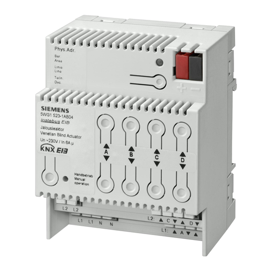
Jalousieaktor N 523/04
Venetian blind actuator N 523/04
5WG1 523-1AB04
Bedien- und Montageanleitung
Operating and Mounting Instructions
Stand: Januar 2008
Issued: January 2008
Jalousieaktor N 523/04
Venetian blind actuator
L1
Netzteil
K1
power supply
Auf
up
K2
Ab
down
K3
Auf
up
K4
Ab
down
K5
Auf
up
K6
Ab
down
K7
Auf
up
K8
Ab
down
L2
Bild / Figure 1
A5E00485308A
DS 03
Produkt- und Funktionsbeschreibung
Der Jalousieaktor N 523/04 ist ein Reiheneinbaugerät im N-Maß
mit 4 TE Breite. An die vier Kanäle des Jalousieaktors kann je-
weils ein Antrieb (Motor) für AC 230V mit elektromechanischen
Endlageschaltern oder mit integrierter Elektronik zur Endlage-
abschaltung angeschlossen werden. Der Parallelbetrieb mehre-
rer Antriebe an einem Kanal erfordert das Zwischenschalten ei-
nes Trennrelais. Außer dem direkten Verfahren des Sonnen-/
Sichtschutzes in eine der beiden Endlagen (über EIS1-Objekte)
können, unabhängig
/Sichtschutz als auch bei Jalousien die Lamellen über Stellbefeh-
le in Prozent (EIS6-Objekte) in Zwischenstellungen gefahren
werden. Ferner wird zwischen Automatik- und Handbetrieb un-
terschieden.
Die Spannungsversorgung der Jalousieaktor-Elektronik erfolgt
über ein integriertes Netzteil, das über den Netzanschluss L1 für
die Kanäle A und B gespeist wird. Der Netzanschluss der Kanäle
C und D erfolgt über den Anschluss L2. Hierdurch wird ermög-
licht, jeweils zwei Kanäle an unterschiedliche Außenleiter anzu-
schließen. Ist dies nicht erforderlich, so ist eine der Klemmen L1
über eine Drahtbrücke mit einer der Klemmen L2 zu verbinden.
Zur Direkt-Bedienung der Kanäle (bei Kommunikationsausfall
oder noch nicht in Betrieb genommener EIB-Kommunikation)
stehen vier Tastenpaare auf der Geräteoberseite zur Verfügung.
Hierzu müssen sowohl AC 230 V als auch Bus-Spannung am Ak-
tor anliegen. Außerdem muss der Aktor über den entsprechen-
den Taster mit LED von Bus- auf Direktbetrieb umgeschaltet
sein. Im Direktbetrieb wird ein Ausgang stets solange einge-
schaltet, wie auf den zugehörigen Taster gedrückt wird. Da der
Direktbetrieb völlig von der Buskommunikation entkoppelt ist,
werden beim Direktbetrieb auch ein ggf. anstehender Alarm
oder eine aktivierte Fahrsperre nicht berücksichtigt.
Hinweis: Nach einem „Entladen" des Applikationsprogramms
mit der ETS ist das Gerät ohne Funktion. Auch ein Direktbetrieb
ist dann nicht mehr möglich.
Weitere Informationen
http://www.siemens.de/gamma
Anschlussbeispiel
siehe Bild 1
Technische Daten
N
Spannungsversorgung
• Busspannung: erfolgt über die Buslinie
Jalousie
• N 523-Elektronik: integriertes Netzteil
Kanal A
230V AC ,+10% / -15%, 50Hz
venetian
blind
• Versorgungsspannung Bus: 21V DC bis 30V DC
channel A
Ein-/Ausgänge
Jalousie
• Netzanschluss:
Kanal B
- 2 x 2-polig (N, L1) (L1 ist auch Versorgung für
venetian
Kanäle A und B)
blind
channel B
- 2-polig L2 (Versorgung für Kanäle C und D)
• 4 Ausgänge für 4 Jalousien:
Jalousie
- jeweils 2-polig (AB, AUF)
Kanal C
- Bemessungsspannung: AC 230 V, 50Hz
venetian
blind
- Bemessungsstrom pro Relaiskontakt:
channel C
6 A (ohmsche Last)
- Schaltzyklen: >20.000 bei cos ϕ = 1
Jalousie
Kanal D
Anschlüsse
venetian
blind
• Netz- und Laststromkreise
channel D
Steckklemmen für Netzspannung und Ausgänge,
Abisolierlänge 9... 10 mm
Jalousieantriebe
Es sind folgende Leiterquerschnitte zulässig:
venetian blind drives
- 0,5... 2,5 mm² eindrähtig
- 0,5... 2,5 mm² feindrähtig, mit Aderendhülse
- 1,5 mm² feindrähtig, unbehandelt (max. Stromtragfähigkeit
6A)
• Buslinie: Druckkontakte auf Datenschiene und Busklemme
• Das Gerät ist mit einem Leitungsschutzschalter der Charakte-
ristik B oder C mit einem max. Nennstrom von 10 A abzusi-
chern!
V
GEFAHR
Beim Durchschleifen des L- und N-Leiters ist zu beachten, dass,
bedingt durch die zulässige Leiterbahnbelastung, der maximale
Klemmenstrom von 10 A nicht überschritten werden darf!
Mechanische Daten
• Abmessungen: Reiheneinbaugerät im N-Maß,
Breite: 4 TE (1 TE = 18 mm)
• Gewicht: ca. 260 g
Elektrische Sicherheit
• Schutzart (nach EN 60529): IP 20
Umweltbedingungen
• Umgebungstemperatur im Betrieb: - 5 ... + 45 °C
• Lagertemperatur: - 25 ... + 70 °C
Prüfzeichen
KNX / EIB
D
voneinander,
sowohl
der Sonnen-
Seite 1 von 2
GB
Product and Applications Description
The Venetian blind actuator N 523/04 is a DIN rail mounted de-
vice in N-system dimensions with a width of 4 module units.
Only one AC 230V drive (motor) with electromechanical limit
switches or with integrated electronics for disconnection at the
limit positions can be connected to one channel of the 4-fold
Venetian blind actuator N 523/04. The parallel operation of se-
veral drives on one channel requires the intermediate switching
of a special relay. Apart from the possibility to travel the sun-/
sight guard directly into one of its two final positions (via EIS 1
objects) it is also possible for both the shutter and the slats to
be moved independently into intermediate positions, defined in
percentages, by positioning commands (EIS 6 objects). And it
can be distinguished between automatic / manual mode.
The power supply of the Venetian blind actuator electronics is
carried out via an integrated power supply unit, which is fed via
the mains connection L1 for channels A and B. The mains con-
nection for channels C and D is carried out via the connection
L2. This enables two channels to be connected to different L-
conductors. If this is not required, one of the terminals L1 must
be linked to one of the terminals L2 via a wiring jumper.
For direct operation (also in the event of communications fail-
ure or if EIB communication has not yet been put into opera-
tion), four pairs of push buttons are available on the top of the
device. For direct operation, both AC 230 V and bus voltage
must be applied at the actuator. Moreover, the actuator must
be switched to direct operation via the appropriate push button
with an LED. In direct operation mode, an output remains
switched on while the associated push button is pressed. As the
direct operation is completely independent of the bus commu-
nication, any active alarm or active blocking of the raising or
lowering of the sun/anti-glare protection is not taken into ac-
count.
Note: After an "unload" of the application program with the ETS
the device will be without any function. Even the direct opera-
tion is impossible.
Additional Information
http://www.siemens.com/gamma
Example of Operation
see figure 1
Technical Specifications
Power supply
• Bus voltage: carried out via the bus line
• N 523 electronics: integrated power supply unit
230V AC, +10% / -15%, 50Hz
• Supply voltage for bus: 21V DC to 30V DC
Inputs/outputs
• Mains connection:
- 2 x 2-pole (N, L1) (L1 is also the power supply for
channels A and B)
- 2-pole L2 (power supply for channels C and D)
• 4 outputs for 4 Venetian blinds:
- each 2-pole (UP, DOWN)
- rated voltage: AC 230 V, 50Hz
- rated current per relay contact:
6 A (resistive load)
- Switching cycles: >20,000 at cos ϕ = 1
Connections
• Mains and load circuits
plug-in terminals for mains connections and outputs
Insulation strip length 9... 10 mm
The following conductor cross-sections are permitted:
- 0.5... 2.5 mm² single-core
- 0.5... 2.5 mm² finely stranded with connector sleeve
- 1.5 mm² finely stranded, untreated (max. ampacity 6A).
• Bus line: Pressure contacts on data rail and bus terminal
• The device must be fused with a miniature circuit breaker of
characteristic B or C with a max. nominal current of 10 A.
V
DANGER
When looping through the L and N conductors, it should be no-
ted that the maximum terminal current of 10 A, which is limited
by the permitted printed conductor load, may not be exceeded.
Mechanical data
• Dimensions: DIN rail mounted device in N-system dimen-
sions, width: 4 modules (1 module = 18 mm)
• Weight: approx. 260 g
Electrical safety
• Protection type (in accordance with EN 60529): IP 20
Environmental conditions
• Ambient operating temperature: - 5 ... + 45 °C
• Storage temperature: - 25 ... + 70 °C
Markings
KNX / EIB
page 1 of 2
Advertisement

Related Manuals for Siemens 5WG1 523-1AB04


Summary of Contents for Siemens 5WG1 523-1AB04
- Page 1 Der Parallelbetrieb mehre- limit positions can be connected to one channel of the 4-fold 5WG1 523-1AB04 rer Antriebe an einem Kanal erfordert das Zwischenschalten ei- Venetian blind actuator N 523/04. The parallel operation of se- nes Trennrelais.
- Page 2 • Die Bedienungsanleitung ist dem Kunden auszuhändigen. • The operating instructions must be handed over to the client. • Ein defektes Gerät ist an die zuständige Geschäftsstelle der • Any faulty devices should be returned to the local Siemens Siemens AG zu senden. office.