
Related Manuals for ABB ACS880-07C


Summary of Contents for ABB ACS880-07C
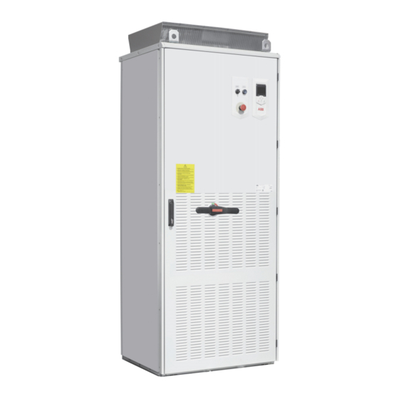
- Page 1 — ABB INDUSTRIAL DRIVES Hardware manual ACS880-07C drives (45 to 710 kW, 50 to 700 hp)
- Page 2 ACS-AP-X assistant control panels user’s manual 3AUA0000085685 3AXD50000022895 ACS880-07C lifting device user’s manual 3AUA0000131337 3AXD50000016067 ABB Drive Connectivity Control Panel User’s manual 3AXD50000515110 3AXD50000514663 Drive firmware manuals and guides ACS880 primary control program firmware manual 3AUA0000085967 3AXD50000009105 Quick start-up guide for ACS880 drives with primary...
- Page 3 Hardware manual ACS880-07C drives (45 to 710 kW, 50 to 700 hp) Table of contents 1. Safety instructions 4. Mechanical installation 6. Electrical installation 10. Start-up 2022 ABB. All Rights Reserved. 3AXD50000764860 Rev A EFFECTIVE: 2022-8-26...
-
Page 5: Table Of Contents
Table of contents 1. Safety instructions Contents of this chapter ..........13 Use of warnings . - Page 6 Additional requirements for the braking applications ..... . 53 Additional requirements for ABB high-output and IP23 motors ....53 Additional requirements for non-ABB high-output and IP23 motors .
- Page 7 Control panel cable length and type ........59 Routing the cables .
- Page 8 Connecting the external power supply cables for the cabinet heater and lighting and motor heater (options +G300, +G301) ....... . . 84 Connecting a PC .
- Page 9 12. Maintenance Contents of this chapter ..........111 Maintenance intervals .
- Page 10 R7/R8: Input cable terminal size (incoming switch OT315, option +F250) ..156 R9: Input cable terminal size (incoming switch OT315/OT400, option +F250) ..157 R9: Input cable terminal size (incoming switch OT630, option +F250) ..158 R6/ R7/R8: Output cable terminal size (DU/DT filter, option +E205) .
- Page 11 Providing feedback on ABB Drives manuals ....... . . 187...
-
Page 13: Safety Instructions
Safety instructions 13 Safety instructions Contents of this chapter This chapter contains the safety instructions which you must obey when you install and operate the drive and do maintenance on the drive. If you ignore the safety instructions, injury, death or damage can occur. Use of warnings Warnings tell you about conditions which can cause injury or death, or damage to the equipment. -
Page 14: General Safety In Installation, Start-Up And Maintenance
14 Safety instructions General safety in installation, start-up and maintenance These instructions are for all personnel that install the drive and do maintenance work on WARNING! Obey these instructions. If you ignore them, injury or death, or damage to the equipment can occur. - Page 15 Safety instructions 15 • Do not use the module installation ramp with plinth heights which exceed the maximum height (50 mm [1.97 in]) marked on the ramp. • Secure the module installation ramp carefully. • To prevent the drive module from falling, attach its top lifting lugs with chains to the cabinet lifting lug before you push the module into the cabinet and pull it from the cabinet.
-
Page 16: Electrical Safety In Installation, Start-Up And Maintenance
16 Safety instructions Note: • If you select an external source for start command and it is on, the drive will start immediately after fault reset unless you configure the drive for pulse start. See the firmware manual. • When the control location is not set to Local, the stop key on the control panel will not stop the drive. -
Page 17: Additional Instructions And Notes
Safety instructions 17 Additional instructions and notes WARNING! Obey these instructions. If you ignore them, injury or death, or damage to the equipment can occur. • Keep the cabinet doors closed when the drive is powered. With the doors open, a risk of a potentially fatal electric shock, arc flash or high-energy arc blast exists. - Page 18 18 Safety instructions • Handle the fiber optic cables with care. • When you unplug the cables, always hold the connector, not the cable itself. • Do not touch the ends of the fibers with bare hands as the ends are extremely sensitive to dirt.
-
Page 19: Grounding
Safety instructions 19 Grounding These instructions are for all personnel who are responsible for the grounding of the drive. WARNING! Obey these instructions. If you ignore them, injury or death and equipment malfunction can occur, and electromagnetic interference can increase. •... -
Page 20: Additional Instructions For Permanent Magnet Motor Drives
20 Safety instructions Additional instructions for permanent magnet motor drives Safety in installation, start-up and maintenance These are additional warnings concerning permanent magnet motor drives. The other safety instructions in this chapter are also valid. WARNING! Obey these instructions. If you ignore them, injury or death and equipment malfunction can occur. -
Page 21: Introduction To The Manual
Introduction to the manual 21 Introduction to the manual Contents of this chapter This chapter describes the manual. It contains a flowchart of steps in checking the delivery, installing and starting up the drive. The flowchart refers to chapters/sections in this manual and to other manuals. -
Page 22: Related Manuals
22 Introduction to the manual Electrical installation gives instructions on wiring the drive. Control unit of frames R6 to R9 contains the default I/O connection diagram, descriptions of the terminals and technical data for the control unit. Control unit of frames R10 and R11 contains the default I/O connection diagram and references for the descriptions of the terminals and technical data of the control unit. -
Page 23: Terms And Abbreviations
Introduction to the manual 23 Task Unpack and check the units (only intact units may be started up). Mechanical installation (page 41) Examine that all necessary option modules and equipment are If the drive has been non- present and correct. operational for more than one year, the converter DC link capacitors Mount the drive. - Page 24 24 Introduction to the manual Term/ Explanation Abbreviation FEPL-02 Optional Ethernet POWERLINK adapter module FENA-11 Optional Ethernet adapter module for EtherNet/IP™, Modbus TCP and PROFINET IO protocols FENA-21 Optional Ethernet adapter module for EtherNet/IP™, Modbus TCP and PROFINET IO protocols, 2-port FPBA-01 Optional PROFIBUS DP adapter module FEN-01...
-
Page 25: Operation Principle And Hardware Description
This chapter briefly describes the operation principle and construction of the drive. Product overview The ACS880-07C is an air-cooled cabinet-installed drive for controlling asynchronous AC induction motors, permanent magnet synchronous motors, AC induction servomotors and ABB synchronous reluctance motors (SynRM motors) with option N7502. -
Page 26: Single-Line Circuit Diagram Of The Drive
26 Operation principle and hardware description Single-line circuit diagram of the drive Main switch-disconnector (switch fuse, switch-disconnector and separate fuses) Optional line contactor (+F250) Auxiliary voltage transformer supplying 24 V and 230/115 V control voltage for, eg, cabinet fan(s), control devices and I/O extension adapter module. -
Page 27: Block Diagram Of The Brake And Dc Options (+D150)
Operation principle and hardware description 27 Block diagram of the brake and DC options (+D150) Drive module cubicle Drive module Brake resistor cubicle Rectifier. Converts alternating current and voltage to direct current and voltage. DC link. DC circuit between rectifier and inverter. DC choke is included in frames R6 to R9. An AC input choke is included in frames R10 and R11. -
Page 28: General Information On The Cabinet Layout
28 Operation principle and hardware description General information on the cabinet layout IP22/IP42... -
Page 29: Cabinet Layout Of Frames R6 To R9
Operation principle and hardware description 29 Cabinet layout of frames R6 to R9 The cabinet layout is shown below. Drive control panel Drive module Door switches and lights, see page 33. Control unit, see page 89. Main switch handle Optional terminal block for external control unit connections (X504, option +L504) Main switch-disconnector... -
Page 30: Cabinet Layout Of Frames R10 To R11
30 Operation principle and hardware description Cabinet layout of frames R10 to R11 The cabinet layout is shown below. Drive control panel Drive module Door switches and lights, see page 33. Control unit, see page 89. Main switch handle Optional terminal block for external control unit connections (X504, option +L504) Main switch-disconnector... -
Page 31: Overview Of Power And Control Connections
Operation principle and hardware description 31 Overview of power and control connections The diagram shows the power connections and control interfaces of the drive. Slot 1 X208 Slot 2 Slot 3 ..M 3 ~ UDC+ UDC-... - Page 32 32 Operation principle and hardware description The layout of external control connection terminals at the side of the drive cabinet is shown below. The composition depends on the options selected. Terminals for X250 Auxiliary contacts of optional line X951 -X951 contactor (+F250) X307 External control power supply (option...
-
Page 33: Door Switches And Lights
Operation principle and hardware description 33 Door switches and lights Label in English Label in local Description language MAIN CONT. Operating switch with option +F250 Opens the main contactor (Q2) Closes the main contactor (Q2) EMERGENCY Emergency stop reset push button with options +Q951,+Q952, STOP RESET +Q963 and +Q964 EMERGENCY... -
Page 34: Control Panel
When a PC is connected to the control panel, the control panel keypad is disabled. Descriptions of cabinet options Note: All options are not available for all drive types, do not coexist with certain other options, or may require additional engineering. Check actual availability with ABB. Degree of protection ... -
Page 35: Ip42 (Option +B054)
Operation principle and hardware description 35 IP42 (option +B054) This option provides the degree of protection of IP42. The air inlet of cabinet door and air outlet on the top of cabinet are covered with metallic meshes. Resistor braking (options +D150) ... -
Page 36: Additional Terminal Block X504 (Option +L504)
36 Operation principle and hardware description +G307) The option provides terminals for connecting external uninterruptible control voltage to the control unit and control devices when the drive is not powered. See also • Supplying power for the auxiliary circuits on page •... -
Page 37: Pt100 Relays (Options +3L506, +5L506, +8L506)
Operation principle and hardware description 37 Pt100 relays (options +3L506, +5L506, +8L506) What the option contains The standard Pt100 relay option includes three (+3L506), five (+5L506) or eight (+8L506) Pt100 temperature monitoring relays and an auxiliary relay wired to a terminal block. Other numbers of Pt100 relays must be ordered as application engineered. -
Page 38: Type Designation Key
38 Operation principle and hardware description Type designation key The type designation contains information on the specifications and configuration of the drive. The first digits from left express the basic configuration. The optional selections are given thereafter, separated by plus signs, eg, +E205. The main selections are described below. - Page 39 Operation principle and hardware description 39 CODE DESCRIPTION Basic codes ACS880 Product series When no options are selected: cabinet-installed drive, IP22, main switch-disconnector (switch fuse with aR fuses), ACS-AP-W assistant control panel, no EMC filter, input DC choke (frames R6 to R9), input AC choke (frames R10 and R11), coated boards, ACS880 primary control program, Safe torque off function, bottom entry and exit of cables, multilingual device label sticker, USB memory stick containing circuit diagrams and all manuals.
- Page 40 40 Operation principle and hardware description CODE DESCRIPTION L503 FDCO-01 optical DDCS communication adapter module L508 FDCO-02 optical DDCS communication adapter module L504 Additional I/O terminal block L505 Thermistor relay (one or two pcs) L506 Pt100 relay (2, 3, 5 or 8 pcs) L516 FEN-21 resolver interface module L517...
-
Page 41: Mechanical Installation
Mechanical installation 41 Mechanical installation Contents of this chapter This chapter describes the mechanical installation procedure of the drive. Examining the installation site Examine the installation site: • The installation site is sufficiently ventilated or cooled to transfer away the drive losses. -
Page 42: Necessary Tools
42 Mechanical installation Note: For easy maintenance, do not install the drives of frames R10 and R11 on a higher level than the floor in front of it. Otherwise the ramp supplied with the drive cannot be used when replacing the drive modules that run on wheels. Necessary tools The tools required for moving the unit to its final position, fastening it to the floor and wall and tightening the connections are listed below:... -
Page 43: Moving And Unpacking The Drive
Mechanical installation 43 Moving and unpacking the drive Move the drive in its original pallet, preferably in the original package to installation site as shown below to avoid damaging the cabinet surfaces and door devices. When you use a pallet truck, check its load capacity before you move the drive. 1088 Lifting the transport package with slings. -
Page 44: Unpacking The Transport Package
44 Mechanical installation Unpacking the transport package Unpack the transport package as follows: 1. Undo the screws that hold the wooden elements of the transport crate together. 2. Remove the elements. 3. Remove the clamps with which the drive cabinet is mounted onto the transport pallet by undoing the fastening screws. -
Page 45: Fastening The Cabinet To The Floor
Mechanical installation 45 Fastening the cabinet to the floor General rules • The drive must be installed in an upright vertical position. • The cabinet can be installed with its back against a wall (a), or back-to-back with another unit (b). •... -
Page 46: Fastening Methods
46 Mechanical installation Fastening methods Fasten the cabinet to the floor by using clamps along the edge of the cabinet bottom, or by bolting the cabinet to the floor through the holes inside (if they are accessible). Alternative 1 – Clamping ... -
Page 47: Miscellaneous
Mechanical installation 47 Miscellaneous Cable duct in the floor below the cabinet A cable duct can be constructed below the 500 mm wide middle part of the cabinet. The cabinet weight lies on the two 50 mm wide transverse sections which the floor must carry. Prevent the cooling air flow from the cable duct to the cabinet by bottom plates. -
Page 48: Arc Welding
48 Mechanical installation Arc welding Fastening the cabinet by arc welding is not recommended. However, if the arc welding is the only mounting option, proceed as follows: Connect the return conductor of the welding equipment to the cabinet frame at the bottom within 0.5 meters (1.5 ft) of the welding point. Note: The thickness of the zinc coating of the cabinet frame is 100 to 200 micrometers. -
Page 49: Guidelines For Planning The Electrical Installation
ABB does not assume any liability whatsoever for any installation which breaches the local laws and/or other regulations. Furthermore, if the recommendations given by ABB are not followed, the drive may experience problems that the warranty does not cover. -
Page 50: Examining The Compatibility Of The Motor And Drive
Examining the compatibility of the motor and drive Use an asynchronous AC induction motor, permanent magnet synchronous motor, AC induction servomotor or ABB synchronous reluctance motor (SynRM motor) with the drive. Select the motor size and drive type from to the rating tables in chapter Technical data basis of the AC line voltage and motor load. -
Page 51: Requirements Table
Motor Nominal AC Requirement for type supply voltage Motor ABB du/dt and common mode filters, insulated N-end insulation motor bearings system < 100 kW 100 kW < P < 350 kW > 350 kW and frame size <... - Page 52 52 Guidelines for planning the electrical installation Motor Nominal AC Requirement for type supply voltage Motor ABB du/dt and common mode filters, insulated N-end insulation motor bearings system < 100 kW 100 kW < P < 350 kW > 350 kW and frame size <...
-
Page 53: Additional Requirements For Abb Motors Of Types Other Than M2_, M3_, M4_, Hx_ And
Additional requirements for ABB high-output and IP23 motors The rated output power of high output motors is higher than what is stated for the particular frame size in EN 50347 (2001). This table shows the requirements for ABB random-wound motor series (for example, M3AA, M3AP and M3BP). -
Page 54: Additional Requirements For Non-Abb High-Output And Ip23 Motors
The rated output power of high output motors is higher than what is stated for the particular frame size in EN 50347 (2001). The table below shows the requirements for random- wound and form-wound non-ABB motors with nominal power smaller than 350 kW. For bigger motors, consult the motor manufacturer. -
Page 55: Additional Data For Calculating The Rise Time And The Peak Line-To-Line Voltage
Guidelines for planning the electrical installation 55 Additional data for calculating the rise time and the peak line-to-line voltage If you need to calculate the actual peak voltage and voltage rise time considering the actual cable length, proceed as follows: •... -
Page 56: Selecting The Power Cables
56 Guidelines for planning the electrical installation Selecting the power cables General rules Select the input power and motor cables according to local regulations: • Select a cable capable of carrying the drive nominal current. See section Ratings (page 137) for the rated currents. Select a cable rated for at least 70 °C (158 ℉)maximum permissible temperature of •... -
Page 57: Typical Power Cable Sizes
For the cable sizes accepted by the drive cabinet lead- throughs and connection terminals, see page 146. Drive type Frame size Cu cable type Al cable type = 400 V ACS880-07C-0105A-3 3×50 3×70 ACS880-07C-0145A-3 3×95 3×120 ACS880-07C-0169A-3 3×120 3×150... -
Page 58: Alternative Power Cable Types
58 Guidelines for planning the electrical installation Alternative power cable types The recommended and not allowed power cable types to be used with the drive are presented below. Recommended power cable types Symmetrical shielded cable with three phase conductors and a concentric PE conductor as shield. -
Page 59: Planning The Braking System
Relay cable type The cable type with braided metallic screen (for example ÖLFLEX by LAPPKABEL, Germany) has been tested and approved by ABB. Control panel cable length and type In remote use, the cable connecting the control panel to the drive must not be longer than three meters (10 ft). -
Page 60: Separate Control Cable Ducts
60 Guidelines for planning the electrical installation other cables in order to decrease electromagnetic interference caused by the rapid changes in the drive output voltage. Where control cables must cross power cables, make sure they are arranged at an angle as near to 90 degrees as possible. -
Page 61: Implementing Thermal Overload And Short-Circuit Protection
Guidelines for planning the electrical installation 61 Implementing thermal overload and short-circuit protection Protecting the drive and input power cable in short-circuits The drive is equipped with internal AC fuses (1) as standard. The fuses restrict drive damage and prevent damage to adjoining equipment in case of a short-circuit inside the drive. -
Page 62: Protecting The Drive And The Input Power And Motor Cables Against Thermal Overload
62 Guidelines for planning the electrical installation Protecting the drive and the input power and motor cables against thermal overload The drive protects itself and the input and motor cables against thermal overload when the cables are sized according to the nominal current of the drive. No additional thermal protection devices are needed. -
Page 63: Implementing The Safe Torque Off Function
Guidelines for planning the electrical installation 63 See the appropriate user’s manual for the wiring, start-up and operation instructions. Option Manual code User’s manual code (English) +Q951 Emergency stop, stop category 0 (using main contactor/breaker) 3AUA0000119895 +Q952 Emergency stop, stop category 1 (using main contactor/breaker) 3AUA0000119896 +Q963 Emergency stop, stop category 0 (using Safe torque off) 3AUA0000119908... -
Page 64: Implementing A Safety Switch Between The Drive And The Motor
64 Guidelines for planning the electrical installation WARNING! Do not connect power factor compensation capacitors or harmonic filters to the motor cables (between the drive and the motor). They are not meant to be used with AC drives and can cause permanent damage to the drive or themselves. -
Page 65: Implementing A Bypass Connection
Guidelines for planning the electrical installation 65 Implementing a bypass connection If bypassing is required, employ mechanically and/or electrically interlocked contactors between the motor and the drive and between the motor and the power line. Make sure with interlocking that the contactors cannot be closed simultaneously. WARNING! Never connect the drive output to the electrical power network. -
Page 66: Connecting A Motor Temperature Sensor To The Drive I/O
66 Guidelines for planning the electrical installation Connecting a motor temperature sensor to the drive I/O WARNING! IEC 60664 requires double or reinforced insulation between live parts and the surface of accessible parts of electrical equipment which are either non- conductive or conductive but not connected to the protective earth. -
Page 67: Electrical Installation
Electrical installation 67 Electrical installation Contents of this chapter This chapter gives instructions on the wiring the drive. Warnings WARNING! If you are not a qualified electrician do not do the installation work described in this chapter. Obey the instructions in chapter Safety instructions. -
Page 68: Motor And Motor Cable
Protective Earth conductor using a measuring voltage of 1000 V DC. The insulation resistance of an ABB motor must exceed 100 Mohm (reference value at 25 °C or 77 °F). For the insulation resistance of other motors, consult the manufacturer’s instructions. - Page 69 Electrical installation 69 Corner-grounded and midpoint-grounded 525…690 V delta network Do not use the drive in corner-grounded and midpoint-grounded 525…690 V delta network. Disconnection from the EMC filter and phase-to-ground varistor will not prevent the damage to the drive.
-
Page 70: Connecting The Power Cables
70 Electrical installation Connecting the power cables Connection diagram ACS880-07C UDC+ T1/ T2/ T3/ R+ UDC- UDC- UDC+ (PE) (PE) 3 ~ M Use a separate grounding PE cable (1a) or a cable with a separate PE conductor (1b) if the conductivity of the shield does not meet the requirements for the PE conductor (see page 56). -
Page 71: Layout Of The Power Cable Connection Terminals And Lead-Throughs (Frames R6 To R9)
Electrical installation 71 Note: If there is a symmetrically constructed grounding conductor on the motor cable in addition to the conductive shield, connect the grounding conductor to the grounding terminal at the drive and motor ends. Do not use an asymmetrically constructed motor cable. Connecting its fourth conductor at the motor end increases bearing currents and causes extra wear. -
Page 72: Layout Of The Power Cable Connection Terminals And Lead-Throughs (Frames R10 To R11)
72 Electrical installation Layout of the power cable connection terminals and lead-throughs (frames R10 to R11) Strain relief Power cable lead-throughs. Conductive sleeve under the grommet. Control cable lead-through with EMI conductive cushions. PE terminal Input power cable terminals L1, L2 and L3 Motor cable terminals U2, V2, W2... -
Page 73: Lead-Through Of External Resistor And Dc Cables
11. Fasten the conductive sleeves to the cable shields with cable ties. 12. Seal the slot between the cable and mineral wool sheet (if used) with sealing compound (eg, CSD-F, ABB brand name DXXT-11, code 35080082). 13. Tie up the unused conductive sleeves with cable ties. - Page 74 74 Electrical installation...
-
Page 75: Grounding The Motor Cable Shield At The Motor End
Electrical installation 75 Grounding the motor cable shield at the motor end Always ground the motor cable shield at the motor end. For minimum radio frequency interference, ground the motor cable shield 360 degrees at the lead-through of the motor terminal box See also Continuous motor cable shield or enclosure for equipment on the motor cable... -
Page 76: Grounding The Outer Shields Of The Control Cables At The Cabinet Lead-Through
76 Electrical installation Grounding the outer shields of the control cables at the cabinet lead-through Applicability This section applies to drives without solid cable conduit plate. Procedure Ground the outer shields of all control cables 360 degrees at the EMI conductive cushions as follows: 1. - Page 77 Electrical installation 77 Stripped cable Conductive surface of the shield exposed Stripped part covered with copper foil Cable shield Copper foil Shielded twisted pair Grounding wire Note for entry of cables: When each cable has its own rubber grommet, sufficient IP and EMC protection can be achieved.
-
Page 78: Routing The Control Cables Inside The Cabinet (Frames R6 To R9)
78 Electrical installation Routing the control cables inside the cabinet (frames R6 to R9) Other control line The control line to X504 or ZCU... -
Page 79: Routing The Control Cables Inside The Cabinet (Frames R10 And R11)
Electrical installation 79 Routing the control cables inside the cabinet (frames R10 and R11) Other control line The control line to X504 or ZCU... - Page 80 80 Electrical installation Units without additional I/O terminal block (option L504): Ground the pair-cable shields and all grounding wires to the clamp below the control unit as shown below. Units with additional I/O terminal block (option L504): Ground the pair-cable shields and all grounding wires to the grounding clamp below the terminal block as shown below.
-
Page 81: Connecting The External 230 V Uninterruptible Control Voltage (Ups, Option +G307)
Electrical installation 81 The control line to X504 The control line connect R10 and R11 to X504. The shielding and grounding line are connected to the grounding line clamp under the terminal block. Leave the other ends of the control cable shields unconnected or ground them indirectly via a high-frequency capacitor with a few nanofarads, eg, 3.3 nF / 630 V. -
Page 82: Wiring The Thermistor Relay(S) (Options +L505 And +2L505)
82 Electrical installation Wiring the thermistor relay(s) (options +L505 and +2L505) The external wiring of option +2L505 (two thermistor relays) is shown below. For example, one relay can be used to monitor the motor windings, the other to monitor the bearings. The maximum contact load capacity is 250 V AC 10 A. -
Page 83: Wiring The Pt100 Relays (Options +2L506, +3L506, +5L506 And +8L506)
Electrical installation 83 Wiring the Pt100 relays (options +2L506, +3L506, +5L506 and +8L506) External wiring of eight Pt100 sensor modules is shown below. Contact load capacity 250 V AC 10 A. For the actual wiring, see the circuit diagram delivered with the drive. X506 1 ×... -
Page 84: Connecting The External Power Supply Cables For The Cabinet Heater And Lighting And Motor Heater (Options +G300, +G301)
84 Electrical installation Connecting the external power supply cables for the cabinet heater and lighting and motor heater (options +G300, +G301) See the circuit diagrams delivered with drive. Connect the external power supply wires for the cabinet heater and lighting to terminal block X300 at the back of the mounting plate. -
Page 85: Connecting A Pc
Electrical installation 85 Connecting a PC A PC (with eg. the Drive composer PC tool) can be connected to the idrive as follows: 1. Connect an ACS-AP-W control panel to the drive either by using an Ethernet (eg. CAT5E) networking cable, or by inserting the panel into the panel holder. WARNING! Do not connect the PC directly to the control panel connector of the control unit as this can cause damage. -
Page 86: Setting The Voltage Range Of The Auxiliary Control Voltage Transformer (T21)
86 Electrical installation Setting the voltage range of the auxiliary control voltage transformer (T21) Connect the power supply wires of the auxiliary control voltage transformer according to the power network voltage. N- G G75 75 1,+Y5P*5 1Y7*d4\05*,4'*+Y5* PYU170124I3 7* +U,*,4+ G . -
Page 87: Installing Option Modules
Electrical installation 87 Installing option modules Mechanical installation of I/O extension, fieldbus adapter and pulse encoder interface modules See page for the available slots for each module. Install the option modules as follows: WARNING! Obey the instructions in chapter Safety instructions. - Page 88 88 Electrical installation...
-
Page 89: Control Unit Of Frames R6 To R9
Control unit of frames R6 to R9 89 Control unit of frames R6 to R9 Contents of this chapter This chapter contains the default I/O connection diagram, descriptions of the terminals and technical data for the control unit (ZCU-12) of drive frames R6 to R9. -
Page 90: Layout
90 Control unit of frames R6 to R9 Layout The layout of external control connection terminals of the control unit is shown below. Description XPOW External power input X202 Analog inputs X202 Analog outputs X208 X210 X208 X210 XD2D Drive-to-drive link X205 XRO1 Relay output 1... -
Page 91: Default I/O Connection Diagram Of Frames R6 To R9
Control unit of frames R6 to R9 91 Default I/O connection diagram of frames R6 to R9 XPOW External power input +24VI 24 V DC, 2 A Reference voltage and analog inputs +VREF 10 V DC, R 1…10 kohm -VREF -10 V DC, R 1…10 kohm AGND Ground AI1+... -
Page 92: Notes
92 Control unit of frames R6 to R9 Notes: Current [0(4)…20 mA, R = 100 ohm] or voltage [ 0(2)…10 V, R > 200 kohm] input selected with jumper J1. Change of setting requires reboot of control unit. Current [0(4)…20 mA, R = 100 ohm] or voltage [ 0(2)…10 V, R >... -
Page 93: Ai1 And Ai2 As Pt100, Pt1000, Ptc And Kty84 Sensor Inputs (Xai, Xao)
Control unit of frames R6 to R9 93 AI1 and AI2 as Pt100, Pt1000, PTC and KTY84 sensor inputs (XAI, XAO) Three Pt100, Pt1000 or PTC sensors or one KTY84 sensor for motor temperature measurement can be connected between an analog input and output as shown below. (Alternatively, you can connect the KTY to FIO-11 analog /I/O extension module or FEN-xx encoder interface module.) Do not connect both ends of the cable shields directly to ground. -
Page 94: Di6 (Xdi:6) As Ptc Sensor Input
94 Control unit of frames R6 to R9 DI6 (XDI:6) as PTC sensor input A PTC sensor can be connected to this input for motor temperature measurement as follows. The sensor resistance must not exceed the threshold resistance of the digital input at the motor normal operating temperature. -
Page 95: Safe Torque Off (Xsto)
Control unit of frames R6 to R9 95 This diagram shows the wiring of the drive-to-drive link for frames R6 to R9... . . 3.3 nF > 630 V AC Safe torque off (XSTO) ... - Page 96 96 Control unit of frames R6 to R9 Digital inputs/outputs DIO1 Connector pitch 5 mm (0.2 in), wire size 2.5 mm (14 AWG) and DIO2 As inputs: (XDIO:1 and XDIO:2) 24 V logic levels: “0” < 5 V, “1” > 15 V : 2.0 kohm Input/output mode selection Filtering: 0.25 ms...
- Page 97 Control unit of frames R6 to R9 97 Ground isolation diagram XPOW +24VI +VREF -VREF AGND AI1+ Common mode voltage between AI1- AI2+ channels +30 V AI2- AGND AGND XD2D BGND XRO1, XRO2, XRO3 XD24 DIIL +24VD DICOM +24VD DIOGND XDIO DIO1 DIO2...
- Page 98 98 Control unit of frames R6 to R9...
-
Page 99: Control Unit Of Frames R10 And R11
Control unit of frames R10 and R11 99 Control unit of frames R10 and Contents of this chapter This chapter contains the default I/O connection diagram, descriptions of the terminals and technical data for the control unit (ZCU-14) of drive frames R10 and R11. -
Page 100: Layout
100 Control unit of frames R10 and R11 Layout The layout of the external control connection terminals of the control unit is shown below. Description XPOW External power input XRO1 Analog inputs Analog outputs XRO2 XD2D Drive to drive link XRO1 Relay output RO1 XRO3... -
Page 101: Default I/O Connection Diagram Of Frames R10 And R11
Control unit of frames R10 and R11 101 Default I/O connection diagram of frames R10 and R11 Relay outputs XRO1…XRO3 Ready 250 V AC / 30 V DC Running 250 V AC / 30 V DC Faulted(-1) 250 V AC / 30 V DC Fault External power input XPOW... -
Page 102: Notes
102 Control unit of frames R10 and R11 Notes: Current [0(4)…20 mA, R = 100 ohm] or voltage [ 0(2)…10 V, R > 200 kohm] input selected with jumper J1. Change of setting requires reboot of control unit. Current [0(4)…20 mA, R = 100 ohm] or voltage [ 0(2)…10 V, R >... - Page 103 Control unit of frames R10 and R11 103 This diagram shows the wiring of the drive-to-drive link for frames R10 and R11.
-
Page 104: Ground Isolation Diagram
104 Control unit of frames R10 and R11 Ground isolation diagram XPOW +24VI +VREF -VREF AGND AI1+ Common mode voltage between AI1- AI2+ channels +30 V AI2- AGND AGND XD2D BGND XRO1, XRO2, XRO3 XD24 DIIL +24VD DICOM +24VD DIOGND XDIO DIO1 DIO2... -
Page 105: Installation Checklist
Installation checklist 105 Installation checklist Contents of this chapter This chapter contains an installation checklist which you must complete before you start up the drive. Warnings WARNING! Obey the instructions in chapter Safety instructions. If you ignore them, injury or death, or damage to the equipment can occur. Checklist Do the steps in section Precautions before electrical work... - Page 106 106 Installation checklist Check that … If the drive is not connected to a symmetrically grounded TN-S system: you have done all the required modificaitons (for example, you may need to disconnect the EMC filter or phase-to-ground varistor) If the drive has been stored over one year: The electrolytic DC capacitors in the DC link of the drive have been reformed.
-
Page 107: Start-Up
Start-up 107 Start-up Contents of this chapter This chapter contains the start-up procedure of the drive. The default device designations (if any) are given in brackets after the name, for example “main switch-disconnector (Q1)”. The same device designations are also used in the circuit diagrams, typically. Start-up procedure Action Safety... -
Page 108: Setting Up The Drive Parameters, And Performing The First Start
For option +N7502, see also For option +N7502, see also SynRM motor control program (option +N7502) for ACS880-01, ACS880-07C, ACS850-04 and ACQ810-04 drives supplement (3AXD50000026332 [English]). If you need more information on the use of the control panel, see ACS-AP-X Assistant control panels user's manual (3AUA0000085685 (English)). -
Page 109: Fault Tracing
Fault tracing 109 Fault tracing Contents of this chapter This chapter describes the fault tracing possibilities of the drive. LEDs Where Color When the LED is lit Control POWER Green Control unit is powered and +15 V is supplied to the control panel panel. - Page 110 110 Fault tracing...
-
Page 111: Maintenance
Note: Long-term operation near the specified maximum ratings or environmental conditions may require shorter maintenance intervals for certain components. The tables below contain user tasks. For tasks to be performed by ABB and more details on the maintenance, consult your local ABB Service representative. On the Internet, go to www.abb.com/searchchannels. -
Page 112: Recommended Maintenance Intervals After Start-Up
Auxiliary cooling fan for circuit boards (R6 to R9) Circuit board compartment cooling fans (R10 and R11) Cabinet cooling fan Cabinet cooling fan Aging Control panel battery and ZCU control unit battery 4FPS10000239703 * Contact ABB Service for the filter change... -
Page 113: Cleaning The Interior Of The Cabinet
See the firmware manual for the actual signal which indicates the running time of the cooling fan. Reset the running time signal after a fan replacement. Replacement fans are available from ABB. Do not use other than ABB specified spare parts. -
Page 114: Replacing The Cabinet Fans (Frames R6 To R9)
114 Maintenance Replacing the cabinet fans (frames R6 to R9) 1. Unplug the cable and remove the fan mounting plate. 2. Remove the fan from the mounting plate. 3. Install the new fan in reverse order. -
Page 115: Replacing The Cabinet Fans (Frames R10 To R11)
Maintenance 115 Replacing the cabinet fans (frames R10 to R11) 1. Remove the plastic plate, cable binding tape and cabinet light. 2. Remove the fixing screws and extract the fan mounting plate. 3. Unplug the cable and remove the fan mounting plate. 4. -
Page 116: Replacing The Drive Module Main Fans (Frames R6 To R8)
116 Maintenance Replacing the drive module main fans (frames R6 to R8) WARNING! Obey the instructions in chapter Safety instructions. If you ignore them, injury or death, or damage to the equipment can occur. 1. Stop the drive and do the steps in section Precautions before electrical work on page before you start the work. -
Page 117: Replacing The Auxiliary Cooling Fan Of The Drive Module (Frames R6 To R9)
Maintenance 117 Replacing the auxiliary cooling fan of the drive module (frames R6 to R9) WARNING! Obey the instructions in chapter Safety instructions. If you ignore them, injury or death, or damage to the equipment can occur. 1. Stop the drive and do the steps in section Precautions before electrical work on page before you start the work. -
Page 118: Replacing The Drive Module Main Fans (Frame R9)
118 Maintenance Replacing the drive module main fans (frame R9) WARNING! Obey the instructions in chapter Safety instructions. If you ignore them, injury or death, or damage to the equipment can occur. 1. Stop the drive and do the steps in section Precautions before electrical work on page before you start the work. -
Page 119: Replacing The Drive Module Main Fans (Frames R10 And R11)
Maintenance 119 Replacing the drive module main fans (frames R10 and R11) WARNING! Obey the instructions in chapter Safety instructions. If you ignore them, injury or death, or damage to the equipment can occur. 1. Stop the drive and do the steps in section Precautions before electrical work on page before you start the work. - Page 120 120 Maintenance Replacing the cooling fan in front of the circuit board compartment (frames R10 and R11) WARNING! Obey the instructions in chapter Safety instructions. If you ignore them, injury or death, or damage to the equipment can occur. 1.
- Page 121 Maintenance 121 9. After replacing with a new fan, install and reset according to the reverse order.
-
Page 122: Replacing The Circuit Board Compartment Cooling Fan (Frames R10 And R11)
122 Maintenance Replacing the circuit board compartment cooling fan (frames R10 and R11) WARNING! Obey the instructions in chapter Safety instructions. If you ignore them, injury or death, or damage to the equipment can occur. 1. Stop the drive and do the steps in section Precautions before electrical work on page before you start the work. -
Page 123: Replacing The Drive Module (Frames R6 To R9)
Required in this replacing procedure: two persons, lifting chains, lifting device, a set of screw drivers and torque wrench with extension bar. A lifting device for ACS880-07C drive modules is available from ABB. For its installation and use, see ACS880-07C lifting device user’s manual (3AUA0000131337 [English]). - Page 124 124 Maintenance 5. Remove the copper bar. 6. Undo the four upper and lower nuts of the drive module.
- Page 125 Maintenance 125 7. Install the sliding rail.
- Page 126 126 Maintenance 8. Pull the drive module out. 9. Secure the drive module with chains from the lifting holes. 10. Lift the module out of the cabinet with the lifting device. 11. Install the new module in reverse order.
-
Page 127: Replacing The Drive Module (Frames R10 And R11)
Maintenance 127 Replacing the drive module (frames R10 and R11) This replacing procedure requires: two persons, installation ramp, a set of screw drivers and a torque wrench with an extension bar. The drawings show frame R11. The details in frame R10 are slightly different. WARNING! Obey the instructions in chapter Safety instructions. - Page 128 128 Maintenance 1. Stop the drive and do the steps in section Precautions before electrical work on page before you start the work. 2. Remove the shroud in front of the module. 3. Remove the swing-out frame and hang it at point number 3. 4.
- Page 129 Maintenance 129 5. Unplug the control terminal of ZCU. 6. Disconnect the drive module busbars from the input cabling panel. Combi screw M12, 70 N·m (52 lbf·ft).
- Page 130 130 Maintenance 7. Disconnect the drive module busbars from the output cabling panel. Combi screw M12, 70 N·m (52 lbf·ft).
- Page 131 Maintenance 131 8. Undo the screws that fasten the drive module to the cabinet at the top and behind the front support legs.
- Page 132 132 Maintenance 9. Fasten the extraction ramp to the cabinet base with two screws.
-
Page 133: Capacitors
Capacitor failure is often unpredicable.It is usually followed by damage to the unit and an input cable fuse failure, or a fault trip. Contact ABB if capacitor failure is suspected. Replacements are available from ABB. Do not use other than ABB specified spare parts. -
Page 134: Replacing The Control Panel Battery
134 Maintenance Replacing the control panel battery The battery is housed on the rear of the control panel. Replace with a new CR 2032 battery. Dispose the old battery according to local disposal rules or applicable laws. Replacing the control unit battery 1. -
Page 135: Transferring The Memory Unit
Maintenance 135 Transferring the memory unit WARNING! Obey the instructions in chapter Safety instructions. If you ignore them, injury or death, or damage to the equipment can occur. 1. Stop the drive and do the steps in section Precautions before electrical work on page before you start the work. - Page 136 136 Maintenance...
-
Page 137: Technical Data
Technical data 137 Technical data Contents of this chapter This chapter contains the technical specifications of the drive, for example, the ratings, sizes and technical requirements, provisions for fulfilling the requirements for CE and other markings. Ratings The nominal ratings for the drives with 50 Hz supply are given below. The symbols are described below the table. -
Page 138: Definitions
Note 2: To achieve the rated motor power given in the table, the rated current of the drive must be higher than or equal to the rated motor current. The DriveSize dimensioning tool available from ABB is recommended for selecting the drive, motor and gear combination. -
Page 139: Derating
+50 °C +104 °F +122 °F For ACS880-07C-430A-3 with Du/Dt option, the ambient temperature derating should be considered as follows: In the temperature range of +35 ... 50°C(+95...122°F), the rated output current is derated by 1% for every added 1 °C (1.8 °F). The output current can be calculated by multiplying the current given in the rating table by the derating factor (k): 1.00... -
Page 140: Altitude Derating
Deratings for special settings in the drive control program Enabling special settings in the drive control program can require output current derating. Low noise Table below gives the deratings when Low noise optimization is selected in Parameter 97.09 Switching freq mode. For non-ABB Ex motors, contact ABB. - Page 141 Technical data 141 Drive module type Output ratings for special settings ACS880-04- Low noise mode Nominal use = 400 V 0105A-3 0145A-3 0169A-3 0206A-3 0246A-3 0293A-3 0363A-3 0430A-3 0505A-3 0585A-3 0650A-3 0725A-3 0820A-3 0880A-3 = 690 V 0061A-7 0084A-7 0098A-7 0119A-7 0142A-7 0174A-7...
-
Page 142: High Speed Mode
Contact ABB for operation above the recommended maximum output frequency or for the output current derating with output frequencies above 120 Hz and below the maximum output frequency. -
Page 143: Low Noise Mode Derating
Typical motor power in no-overload use. The ratings apply at an ambient temperature of 40 °C (104 °F). Low noise mode derating When using low noise mode derating, motor and brake power will be derated. Contact ABB for more information. - Page 144 144 Technical data Fuses (IEC) The drive is equipped with aR fuses listed below. Drive type Input Ultrarapid (aR) fuses (one fuse per phase) ACS880-07C- current Manufacturer Type Size = 400 V 0105A-3 7500 Mersen 170M3414 0145A-3 21000 Mersen 170M4409...
-
Page 145: Dimensions And Weights
Technical data 145 Dimensions and weights Frame size Weight Height Width Depth IP22/42 2138 84.17 16.93 26.50 2138 84.17 16.93 26.50 2138 84.17 16.93 26.50 2138 84.17 20.87 26.50 2138 84.17 32.68 27.48 1170 2138 84.17 32.68 27.48 1280 Free space requirements Front Side Above... -
Page 146: Losses, Cooling Data And Noise
146 Technical data Losses, cooling data and noise Drive type Frame Air flow Heat Noise dissipation dB(A) /min = 400 V ACS880-07C-0105A-3 1050 1795 ACS880-07C-0145A-3 1050 1940 ACS880-07C-0169A-3 1050 2440 ACS880-07C-0206A-3 1050 2810 ACS880-07C-0246A-3 1050 3800 ACS880-07C-0293A-3 1050 4400 ACS880-07C-0363A-3... -
Page 147: Iec - Option +E205
Technical data 147 Frame Connection terminals of input power and motors cables Grounding terminals size L1, L2, L3 T1/U2,T2/V2,T3/W2 Max. cable Bolt size Tightening Max. cable Tightening Bolt size Tightening size torque size torque torque N·m N·m N·m 3×120 15...22 3×120 30...44 3×240... -
Page 148: R6: Input And Output Cable Terminal Size (Incoming Switch Ot160)
148 Technical data R6: Input and output cable terminal size (incoming switch OT160) ... -
Page 149: R7: Input And Output Cable Terminal Size (Incoming Switch Ot160/Ot250)
Technical data 149 R7: Input and output cable terminal size (incoming switch OT160/OT250) -
Page 150: R8: Input And Output Cable Terminal Size (Incoming Switch Ot160/Ot250)
150 Technical data R8: Input and output cable terminal size (incoming switch OT160/OT250) -
Page 151: R7: Input And Output Cable Terminal Size (Incoming Switch Ot315)
Technical data 151 R7: Input and output cable terminal size (incoming switch OT315) ... -
Page 152: R8: Input And Output Cable Terminal Size (Incoming Switch Ot315)
152 Technical data R8: Input and output cable terminal size (incoming switch OT315) ... -
Page 153: R9: Input And Output Cable Terminal Size (Incoming Switch Ot315/Ot400)
Technical data 153 R9: Input and output cable terminal size (incoming switch OT315/OT400) -
Page 154: R9: Input And Output Cable Terminal Size (Incoming Switch Ot630)
154 Technical data R9: Input and output cable terminal size (incoming switch OT630) ... - Page 155 Technical data 155 R6/ R7/R8: Input cable terminal size (incoming switch OT160/OT250, option +F250)
-
Page 156: R7/R8: Input Cable Terminal Size (Incoming Switch Ot315, Option +F250)
156 Technical data R7/R8: Input cable terminal size (incoming switch OT315, option +F250) -
Page 157: R9: Input Cable Terminal Size (Incoming Switch Ot315/Ot400, Option +F250)
Technical data 157 R9: Input cable terminal size (incoming switch OT315/OT400, option +F250) -
Page 158: R9: Input Cable Terminal Size (Incoming Switch Ot630, Option +F250)
158 Technical data R9: Input cable terminal size (incoming switch OT630, option +F250) -
Page 159: R6/ R7/R8: Output Cable Terminal Size (Du/Dt Filter, Option +E205)
Technical data 159 R6/ R7/R8: Output cable terminal size (DU/DT filter, option +E205) ... -
Page 160: R9: Output Cable Terminal Size (Du/Dt Filter, Option +E205)
160 Technical data R9: Output cable terminal size (DU/DT filter, option +E205) ... -
Page 161: R10: Input And Output Cable Terminal Size
Technical data 161 R10: Input and output cable terminal size ... - Page 162 162 Technical data...
- Page 163 Technical data 163...
-
Page 164: R11: Input And Output Cable Terminal Size
164 Technical data R11: Input and output cable terminal size ... - Page 165 Technical data 165...
- Page 166 166 Technical data...
-
Page 167: Terminal Data For The Control Cables
Control unit of frames R10 and on page 99. Electrical power network specification Voltage (U ACS880-07C-xxxxx-3 drives: 380…415 VAC 3-phase +10%…-15%. This is indicated in the type designation label as typical input voltage level 400 V AC. ACS880-07C-xxxxx-7 drives: 525…690 VAC 3-phase +10%…-15%. This is indicated in the type designation label as typical input voltage levels 525/600/690 V AC. -
Page 168: Protection Classes
168 Technical data Protection classes Degrees of protection IP22, IP42 (IEC/EN 60529) Overvoltage category (IEC 60664-1) Protective class (IEC/EN 61800-5-1) Ambient conditions Environmental limits for the drive are given below. The drive is to be used in a heated, indoor, controlled environment. Operation Storage Transportation... -
Page 169: Compliance With The En 61800-3:2004
IEC 62635 guidelines. To aid recycling, plastic parts are marked with an approppriate identification code. Contact your local ABB distributor for further information on environmental aspects and recycling instructions for professional recyclers. End of life treatment must follow international and local regulations. -
Page 170: Category C3
Equipment 2. An EMC plan for preventing disturbances is drawn up for the installation. A template is available from the local ABB representative. 3. The motor and control cables are selected as specified in the hardware manual. 4. The drive is installed according to the instructions given in the hardware manual. -
Page 171: Cyber Security Disclaimer
ABB and its affiliates are not liable for damages and/or losses related to such security breaches, any unauthorized access, interference, intrusion, leakage and/or theft of data or information. - Page 172 172 Technical data...
-
Page 173: Dimension Drawings
Dimension drawings 173 Dimension drawings Example dimension drawings with dimensions in millimeters and [inches] are shown below. -
Page 174: Frame Sizes R6 To R8
174 Dimension drawings Frame sizes R6 to R8... -
Page 175: Frame Size R9
Dimension drawings 175 Frame size R9... -
Page 176: Frame Size R10
176 Dimension drawings Frame size R10... -
Page 177: Frame Size R11
Dimension drawings 177 Frame size R11... - Page 178 178 Dimension drawings...
-
Page 179: Safe Torque Off Function
Safe torque off function 179 Safe torque off function Contents of this chapter For Safe torque off function (STO) of the drive, please refer to th related chapters in ACS880-01 hardware manual and ACS880-04 hardware manual. - Page 180 180 Safe torque off function...
-
Page 181: Resistor Braking
Resistor braking 181 Resistor braking Contents of this chapter This chapter tells how to select, protect and wire brake choppers and resistors. The chapter also contains the technical data. Operation principle and hardware description The drive can be equipped with optional built-in brake chopper (+D150). The brake chopper handles the energy generated by a decelerating motor. -
Page 182: Selecting A Custom Resistor
182 Resistor braking Selecting a custom resistor For resistor, make sure that: 1. The resistance of the custom resistor is greater or equal than the resistance of the default resistor in the rating table on page 185: R > R where Resistance of the custom resistor. -
Page 183: Maximum Cable Length
The maximum length of the resistor cable(s) is 10 m (33 ft). EMC compliance of the complete installation Note: ABB has not verified that the EMC requirements are fulfilled with external user- defined brake resistors and cabling. The EMC compliance of the complete installation must be considered by the customer. -
Page 184: Mechanical Installation Of External Brake Resistors
184 Resistor braking Mechanical installation of external brake resistors All brake resistors must be installed outside the drive. Follow the resistor manufacturer’s instructions. Electrical installation Checking the insulation of the assembly Follow the instructions given under Brake resistor assembly on page 68. -
Page 185: Technical Data
Resistor braking 185 Technical data Ratings Drive type Internal brake External brake chopper resistor(recommand) brcont Rcont = 400 V ACS880-07C-0105A-3 2400 ACS880-07C-0145A-3 2400 ACS880-07C-0169A-3 3600 ACS880-07C-0206A-3 3600 ACS880-07C-0246A-3 5400 13.5 ACS880-07C-0293A-3 5400 13.5 ACS880-07C-0363A-3 5400 13.5 ACS880-07C-0430A-3 5400 13.5 ACS880-07C-0505A-3 2.00... -
Page 186: Terminals And Cable Lead-Through Data
186 Resistor braking Continuous power (heat) dissipation of the resistor when placed correctly Rcont The ratings apply at an ambient temperature of 40 °C (104 °F) Terminals and cable lead-through data See section Terminal and lead-through data for the power cables on page 146. -
Page 187: Further Information
Product and service inquiries Address any inquiries about the product to your local ABB representative, quoting the type designation and serial number of the unit in question. A listing of ABB sales, support and service contacts can be found by navigating to abb.com/searchchannels. - Page 188 © Copyright 2022 ABB. All rights reserved. Specifications subject to change without notice.