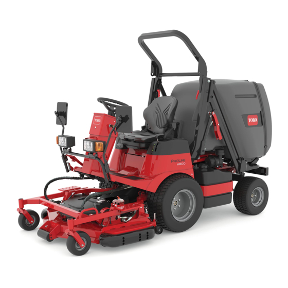
Toro ProLine H800 Setup Instructions
Hide thumbs
Also See for ProLine H800:
- Service manual (343 pages) ,
- Operator's manual (92 pages) ,
- Installation instructions (4 pages)
Advertisement
Quick Links
ProLine H800 Rotary Mower
Model No. 31050TE—Serial No. 319000001 and Up
Setup
Loose Parts
Use the chart below to verify that all parts have been shipped.
Procedure
1
2
3
4
5
6
7
8
Note:
Determine the left and right sides of the machine from the normal operating position.
© 2020—The Toro® Company
8111 Lyndale Avenue South
Bloomington, MN 55420
Description
Mower deck
Machine
Hopper door
Flat washer
Bolt
Locknut
Hook
Spacer
Long bolt
Short bolt
Flat washer
Rod connector
Spring
Bushing
Flange nut
Locknut
Rear bumper
Bolt
Flat washer
Locknut
Cable ties
Front light assembly
Knob
No parts required
Warning decal
Spark arrestor decal
Diesel fuel decal
No parts required
Register at www.Toro.com.
Form No. 3438-558 Rev A
Qty.
1
1
Remove the machine from the crate.
1
6
2
Install the hopper door.
2
1
1
2
1
3
Install the latch.
1
1
2
3
2
1
4
8
Install the rear bumper.
4
4
1
Install the front lights.
2
–
Position the beacon light.
1
1
Install the decals.
1
–
Completing the setup.
Original Instructions (EN)
All Rights Reserved *3438-558* A
Printed in the USA
Setup Instructions
Use
Advertisement

Summary of Contents for Toro ProLine H800
- Page 1 Form No. 3438-558 Rev A ProLine H800 Rotary Mower Model No. 31050TE—Serial No. 319000001 and Up Setup Instructions Setup Loose Parts Use the chart below to verify that all parts have been shipped. Procedure Description Qty. Mower deck Machine Remove the machine from the crate.
-
Page 2: Removing The Machine From The Crate
Removing the Machine from the Crate Parts needed for this procedure: Mower deck Machine Hopper door Procedure Remove the 4 planks that attach the mower-deck crate to the traction-unit crate. Remove the mower deck crate (Figure Remove the hopper door from the crate (Figure g315990 Remove the front panel, plastic bags, and other... -
Page 3: Installing The Latch
Installing the Hopper Door Installing the Latch Parts needed for this procedure: Parts needed for this procedure: Flat washer Hook Bolt Spacer Locknut Long bolt Short bolt Procedure Flat washer Rod connector Remove the hardware from the brackets on the Spring hopper. - Page 4 g315987 Figure 4 1. Long bolt 5. Flange nut 2. Flat washer 6. Locknut 3. Rod connector 7. Short bolt 4. Bushing Check the gap between the hook and the closed hopper door. Ensure that the gap is 2 mm (1/16 inch) and adjust if necessary (Figure g316170...
-
Page 5: Installing The Rear Bumper
Installing the Rear Bumper Parts needed for this procedure: Rear bumper Bolt Flat washer Locknut Cable ties Procedure Remove the hardware from the rear bumper (Figure Install the rear bumper under the hopper with the previously removed hardware (Figure Connect the wire harness to the machine harness. - Page 6 Installing the Front Lights Parts needed for this procedure: Front light assembly Knob Procedure Install the front lights onto the machine brackets by using the slots in the brackets (Figure Tighten the knobs (Figure Connect the wire harness to the machine harness.
-
Page 7: Completing The Setup
Positioning the Beacon Light No Parts Required Procedure Raise the rollbar; refer to the Operator’s Manual. Rotate the beacon light to the upright position and secure the fasteners. g316208 Figure 10 1. Warning decal—install 3. Existing decal over the existing decal 2. - Page 8 Countries Language Language Language Anguilla Guam Puerto Rico Antigua and Guatemala Saint Lucia, Barbuda Saint Kitts and Nevis Argentina Guyana Saint Vincent, Grenadines Bahamas Haiti Samoa, American Barbados India Singapore Belize Israel Sri Lanka Bermuda Jamaica Suriname Bolivia Lebanon Taiwan British Virgin Malaysia Thailand...


