
Related Manuals for Asus Aaeon UP 4000 EDGE


Summary of Contents for Asus Aaeon UP 4000 EDGE
- Page 1 UP 4000 EDGE Edge System UP-EDGE-APL03 User’s Manual 1st Ed Last Updated: September 6, 2022...
- Page 2 Copyright Notice This document is copyrighted, 2022. All rights are reserved. The original manufacturer reserves the right to make improvements to the products described in this manual at any time without notice. No part of this manual may be reproduced, copied, translated, or transmitted in any form or by any means without the prior written permission of the original manufacturer.
- Page 3 Acknowledgement All other products’ name or trademarks are properties of their respective owners. Microsoft®, Windows® are registered trademarks of Microsoft Corp. ⚫ Intel®, Pentium®, and Celeron® are registered trademarks of Intel Corporation ⚫ Intel Atom™ is a trademark of Intel Corporation ⚫...
- Page 4 Packing List Before setting up your product, please make sure the following items have been shipped: Item Quantity UP-EDGE-APL03 (UP 4000 EDGE) with heatsink ⚫ If any of these items are missing or damaged, please contact your distributor or sales representative immediately.
- Page 5 About this Document This User’s Manual contains all the essential information, such as detailed descriptions and explanations on the product’s hardware and software features (if any), its specifications, dimensions, jumper/connector settings/definitions, and driver installation instructions (if any), to facilitate users in setting up their product. Users may refer to the product page at AAEON.com for the latest version of this document.
- Page 6 Safety Precautions Please read the following safety instructions carefully. It is advised that you keep this manual for future references All cautions and warnings on the device should be noted. Make sure the power source matches the power rating of the device. Position the power cord so that people cannot step on it.
- Page 7 If any of the following situations arises, please the contact our service personnel: Damaged power cord or plug Liquid intrusion to the device iii. Exposure to moisture Device is not working as expected or in a manner as described in this manual The device is dropped or damaged Any obvious signs of damage displayed on the device...
- Page 8 FCC Statement This device complies with Part 15 FCC Rules. Operation is subject to the following two conditions: (1) this device may not cause harmful interference, and (2) this device must accept any interference received including interference that may cause undesired operation.
- Page 9 China RoHS Requirements (CN) 产品中有毒有害物质或元素名称及含量 AAEON Main Board/ Daughter Board/ Backplane 有毒有害物质或元素 部件名称 铅 汞 镉 六价铬 多溴联苯 多溴二苯醚 (Pb) (Hg) (Cd) (Cr(VI)) (PBB) (PBDE) 印刷电路板 ○ ○ ○ ○ ○ ○ 及其电子组件 外部信号 ○ ○ ○ ○ ○ ○ 连接器及线材...
- Page 10 China RoHS Requirement (EN) Poisonous or Hazardous Substances or Elements in Products AAEON Main Board/ Daughter Board/ Backplane Poisonous or Hazardous Substances or Elements Hexavalent Polybrominated Polybrominated Component Lead Mercury Cadmium Chromium Biphenyls Diphenyl Ethers (Pb) (Hg) (Cd) (Cr(VI)) (PBB) (PBDE) PCB &...
-
Page 11: Table Of Contents
Table of Contents Chapter 1 - Product Specifications..................1 Specifications ......................2 Chapter 2 – Hardware Information ..................4 Dimensions ....................... 5 Jumpers and Connectors ..................6 List of Connectors ....................8 2.3.1 Dual USB 3.0 (CN4) ..................9 2.3.2 USB3.0 + HDMI (CN5) ................ -
Page 12: Chapter 1 - Product Specifications
Chapter 1 Chapter 1 - Product Specifications... -
Page 13: Specifications
Specifications System Intel® Pentium® N4200/ Celeron® N3350/ Atom E3950™ Memory Onboard LPDDR4 Memory up to 8GB Graphics Intel® Gen 9 HD, supporting 4K Codec Decode and Encode for HEVC4, H.264, VP8 Storage Onboard eMMC Storage, up to 64GB Ethernet Gb Ethernet (full speed) RJ-45 x 1 WIFI/BT —... - Page 14 Power Supply Power Requirement 12V DC-in @ 5A Power Supply Type DC Jack, 5.5-2.1mm/Phoenix Colay Power Consumption (Typical) 12V @ 1.25A (15W) Mechanical Mounting VESA Mounting Dimensions (W x H x D) 3.62" x 2.52" x 1.78" (92mm x 64mm x 45.2mm) Net Weight 0.64 lbs.
-
Page 15: Chapter 2 - Hardware Information
Chapter 2 – Hardware Information Chapter 2... -
Page 16: Dimensions
Dimensions Chapter 2 – Hardware Information... -
Page 17: Jumpers And Connectors
Jumpers and Connectors Top: Chapter 2 – Hardware Information... - Page 18 Bottom: Chapter 2 – Hardware Information...
-
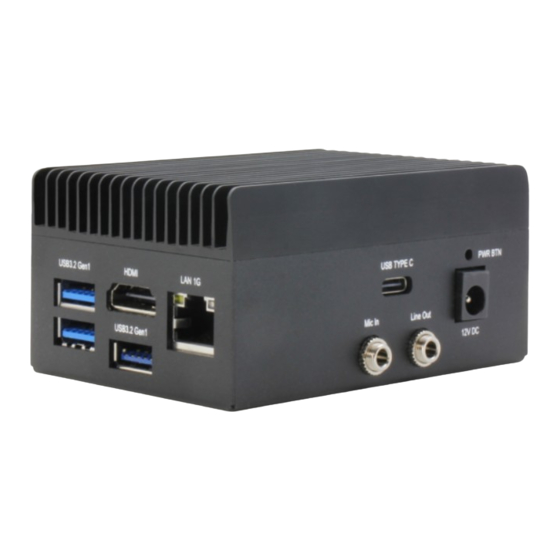
Page 19: List Of Connectors
List of Connectors Please refer to the table below for all of the board’s connectors that you can configure for your application Label Function Dual USB 3.0 USB3.0 + HDMI RJ45 RTC Conn CN10 Type-C 3.0 CN11 DC Jack Power Button Chapter 2 –... -
Page 20: Dual Usb 3.0 (Cn4)
2.3.1 Dual USB 3.0 (CN4) Signal Signal 5V@0.9A for USB 3.0 USB2.0_DN0 USB2.0_DP0 USB3.0_RXN _P0 USB3.0_RXP _P0 USB3.0_TXN _P0 5V@0.9A for USB 3.0 USB3.0_TXP _P0 USB2.0_DN1 USB2.0_DP1 USB3.0_RXN_P1 USB3.0_RXP _P1 USB3.0_TXP _P1 USB3.0_TXN _P1 Chapter 2 – Hardware Information... -
Page 21: Usb3.0 + Hdmi (Cn5)
2.3.2 USB3.0 + HDMI (CN5) Signal Signal HDMI_TMDS_TXP2 HDMI_TMDS_TXN2 HDMI_TMDS_TXP1 HDMI_TMDS_TXN1 HDMI_TMDS_TXP0 HDMI_TMDS_TXN0 HDMI_TMDS_Clock_P HDMI_TMDS_Clock_N HDMI_DDC_Clock HDMI_DDC_Data 5V@1A for HDMI HDMI Hot Plug detect pin 5V@0.9A for USB 3.0 USB2.0_DN_P1 USB2.0_DP_P1 USB3.0_RxN_P1 USB3.0_RxP _P1 USB3.0_TxN_P1 USB3.0_TxP_P1 Chapter 2 – Hardware Information... -
Page 22: Rj45 (Cn6)
2.3.3 RJ45 (CN6) Signal Signal LAN1_MDI0+(TXD+) LAN1_MDI0-(TXD-) LAN1_MDI1+(RXD+) LAN1_MDI1-(RXD-) CT_GND CT_GND LAN1_MDI2+ LAN1_MDI2- LAN1_MDI3+ LAN1_MDI3- LAN Link LED 1000# LAN Link LED 100# LAN Active LED_N LAN Active LED_P Chassis_GND Chassis_GND Chapter 2 – Hardware Information... -
Page 23: Rtc Connector (Cn9)
2.3.4 RTC Connector (CN9) Signal Signal 3.3V for RTC 2.3.5 USB Type-C 3.0 (with Alt Mode) (CN10) Signal Signal USB3.0_ Type-C_TxP_P1 USB3.0_ Type-C_TxN_P1 5V@3A for USB Type-C USB Type-C CC pin1 USB2.0_ Type-C_DP_P1 USB2.0_ Type-C_DN_P1 USB Type-C SBU1 5V@3A for USB Type-C USB3.0_ Type-C_RxP_P2 USB3.0_ Type-C_RxN_P2 USB3.0_ Type-C_TxP_P2... -
Page 24: Dc Jack (5.5-2.1Mm) (Cn11)
Signal Signal USB3.0_ Type-C_TxN_P2 5V@3A for USB Type-C USB Type-C CC pin2 USB2.0_ Type-C_DP_P1 USB2.0_ Type-C_DN_P1 USB Type-C SBU2 5V@3A for USB Type-C USB3.0_ Type-C_RxP_P1 USB3.0_ Type-C_RxN_P1 2.3.6 DC Jack (5.5-2.1mm) (CN11) Signal Signal 12V@7A Input Chapter 2 – Hardware Information... -
Page 25: Power Button (Sw1)
2.3.7 Power Button (SW1) Signal Signal Power Button# Chapter 2 – Hardware Information... -
Page 26: Chapter 3 - Drivers Installation
Chapter 3 Chapter 3 – Drivers Installation... -
Page 27: Driver Download And Installation
Driver Download and Installation Please access https://www.up-community.org and go to the Downloads section > UP 4000 EDGE to find the relevant drivers. Unknown Device Troubleshooting After installing the drivers on Windows 10, you may see five unknown devices in the device manager. - Page 28 PCI Device (8086&DEV_5AC8), Unknown Device (AANT0F01), and VEN_AANT&DEV_1280 Go into the device BIOS Settings. Navigate to the Boot menu. Change OS Selection to “Windows. ” Chapter 3 – Drivers Installation...
- Page 29 PCI Device: The unknown PCI device is the PWM signal. It is provided directly from the Apollo Lake chipset, but Intel has not released a Windows driver for this device. This PCI device is not available for Windows 10, it is only supported by Linux. VEN_AANT&DEV_1280: This is the ADC for Linux, there is no Windows driver.
-
Page 30: Appendix A - Up Framework Sdk Installation
Appendix A Appendix A – UP Framework SDK Installation... -
Page 31: Introduction
Introduction This section provides instructions for the installation of the UP Framework SDK. Instructions are provided for Windows 10 and Windows IoT Core. You can download the latest version of UP Framework SDK from the UP community: https://downloads.up-community.org/download/up-sdk-for-windows-10-and-windows-iot/ A.2 Installation for Windows 10 Step 1 Locate the downloaded file UpFrameworkSetup.msi and run the installer. - Page 32 Step 2 Select the installation folder. Default destination path is C:\Program Files(x86)\AAEON\ You may also choose to install the UP Framework SDK for all users or only the current user. Press “Next” to continue installation. Step 3 Press “Next” to confirm the installation. Appendix A –...
- Page 33 Step 4 Press “Close” to exit once setup is complete. Appendix A – UP Framework SDK Installation...
-
Page 34: A.3 Installation For Windows Iot Core
A.3 Installation for Windows IoT Core Before you begin, make sure you have downloaded and installed the latest version of the Windows IoT Core image from the UP community. Installation requires using a connected PC with the UP Framework SDK software downloaded and saved. - Page 35 Step 2 Download the UP Framework SDK to your PC and unzip the files. Open PowerShell as an Administrator. Run the command RemoteInstallation.ps1 to install the UP Framework SDK. Enter the IP address of the UP IoT Core device when prompted. Appendix A –...