Table of Contents
Advertisement
SERVICE MANUAL
TECHNICAL INFORMATION
FOR SERVICE PERSONNEL ONLY
SPECIFICATIONS
TYPE
MODEL
POWER SOURCE
TOTAL INPUT
TOTAL AMPERES
COOLING
CAPACITY
TOTAL INPUT
TOTAL AMPERES
HEATING
CAPACITY
DIMENSIONS
(mm)
NET WEIGHT
SPECIFICATIONS AND PARTS ARE SUBJECT TO CHANGE FOR IMPROVEMENT
ROOM AIR CONDITIONER
FEBRUARY 2008 Hitachi Household Appliances(Wuhu) Co.,Ltd.
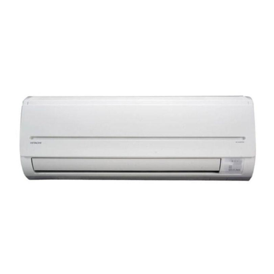
RAS-E14H2A
RAC-E14H2
INDOOR UNIT
RAS-E14H2A
(W)
(A)
(kW)
(B.T.U./h)
(W)
(A)
(kW)
(B.T.U./h)
W
H
D
(kg)
INDOOR UNIT + OUTDOOR UNIT
RAS-E14H2A/RAC-E14H2
REFER TO THE FOUNDATION MANUAL
SPECIFICATIONS ------------------------------------------------------------------- 4
HOW TO USE ----------------------------------------------------------------------- 5
CONSTRUCTION AND DIMENSIONAL DIAGRAM --------------------- 15
MAIN PARTS COMPONENT --------------------------------------------------- 17
WIRING DIAGRAM ---------------------------------------------------------------- 19
CIRCUIT DIAGRAM --------------------------------------------------------------- 20
BLOCK DIAGRAM ----------------------------------------------------------------- 22
BASIC MODE ----------------------------------------------------------------------- 23
REFRIGERATING CYCLE DIAGRAM --------------------------------------- 29
DESCRIPTION OF MAIN CIRCUIT OPERATION ----------------------- 30
TROUBLE SHOOTING ----------------------------------------------------------
PARTS LIST AND DIAGRAM ----------------------------------------------- 90
DC INVERTER (WALL TYPE)
1 PHASE, 50 Hz, 220-230V
1,090 (155 ~ 1,460)
5.22-4.99
3.50 (0.90 ~ 4.00)
11,940 (3,070 ~ 13,650)
1,110 (115 ~ 1,440)
5.32-5.09
4.20 (0.90 ~ 5.00)
14,330 (3,070 ~ 17,060)
780
280
210
9.5
SM0027
CONTENTS
-------------------------
OUTDOOR UNIT
RAC-E14H2
750 (+91)
548
288 (+47)
35
After installation
- 61
88
Advertisement
Table of Contents

Related Manuals for Hitachi RAS-E14H2A


Summary of Contents for Hitachi RAS-E14H2A
-
Page 1: Table Of Contents
CAPACITY (B.T.U./h) 14,330 (3,070 ~ 17,060) 750 (+91) DIMENSIONS (mm) 288 (+47) NET WEIGHT (kg) After installation SPECIFICATIONS AND PARTS ARE SUBJECT TO CHANGE FOR IMPROVEMENT ROOM AIR CONDITIONER INDOOR UNIT + OUTDOOR UNIT FEBRUARY 2008 Hitachi Household Appliances(Wuhu) Co.,Ltd. - Page 2 SAFETY DURING REPAIR WORK In order to disassemble and repair the unit in question, be sure to disconnect the power cord plug from the power outlet before starting the work. If it is necessary to replace any parts, they should be replaced with respective genuine parts for the unit, and the replacement must be effected in correct manner according to the instructions in the Service Manual of the unit.
- Page 3 WORKING STANDARDS FOR PREVENTING BREAKAGE OF SEMICONDUCTORS Scope The standards provide for items to be generally observed in carrying and handling semiconductors in relative manufacturers during maintenance and handling thereof. (They apply the same to handling of abnormal goods such as rejected goods being returned). Object parts (1) Micro computer (2) Integrated circuits (IC)
- Page 4 (6)Use a three wire type soldering iron including a grounding wire. Metal plate (of aluminium, stainless steel, etc.) Working table Resistor of 1 M (1/2W) Staple Earth wire Bare copper wire (for body earth) Fig. 3 Grounding of the working table Soldering iron Grounding wire...
- Page 5 CAUTION In quiet operation or stopping the running, slight flowing noise of refrigerant in the refrigerating cycle is heard occasionally, but this noise is not abnormal for the operation. When it thunders near by, it is recommend to stop the operation and to disconnect the power cord plug from the power outlet for safety.
-
Page 6: Specifications
SPECIFICATIONS RAC-E14H2 RAS-E14H2A MODEL FAN MOTOR 40 W PWM DC35V FAN MOTOR CAPACITOR FAN MOTOR PROTECTOR COMPRESSOR — ASC092SD-A8JT1 COMPRESSOR MOTOR CAPACITOR OVERLOAD PROTECTOR OVERHEAT PROTECTOR FUSE (for MICROPROCESSOR) 3.0A POWER RELAY POWER SWITCH TEMPORARY SWITCH SERVICE SWITCH TRANSFORMER VARISTOR... -
Page 7: How To Use
HOW TO USE PRECAUTIONS DURING OPERATION SAFETY PRECAUTION • Do not use any conductor as fuse wire, this could cause fatal accident. PROHIBITION • Please read the “Safety Precaution” carefully before operating the unit to ensure correct usage of the unit. •... - Page 8 • When the outdoor unit is hung on the ceiling, install the bush and drain pipe on the drain port and drain water. MODEL NAME AND DIMENSIONS MODEL WIDTH (mm) HEIGHT (mm) DEPTH (mm) RAS-E08H2A, RAS-E10H2A, RAS-E14H2A RAC-E08H2, RAC-E10H2 RAC-E14H2 – 4 – – 5 –...
- Page 9 NAMES AND FUNCTIONS OF EACH PART VARIOUS FUNCTIONS I Auto Restart Control REMOTE CONTROLLER • This controls the operation of the indoor unit. • If there is a power failure, operation will be automatically restarted when the power is resumed with The range of control is about 7 meters.
- Page 10 HEATING OPERATION DEHUMIDIFYING OPERATION • Use the device for heating when the outdoor temperature is under 21°C. Use the device for dehumidifying when the room temperature is over 16°C. When it is too warm (over 21°C), the heating function may not work in order to protect the device. When it is under 15°C, the dehumidifying function will not work.
- Page 11 COOLING OPERATION FAN OPERATION Use the device for cooling when the outdoor temperature is -10 to 42°C. You can use the device simply as an air circulator. Use this function to dry the interior of the indoor unit If humidity is very high (over 80%) indoors, some dew may form on the air outlet grille of the indoor at the end of summer.
- Page 12 HOW TO SET THE TIMER Set the current time with Press the (TIME) Time Set the (TIME) button. TIME the TIMER control button. button again. The time • The time indication will disappear automatically in 10 seconds. (current time) indication star ts lighting After you change the instead of flashing.
- Page 13 HOW TO SET THE SLEEP TIMER ADJUSTING THE AIR DEFLECTORS Set the current time at first if it is not set before (see the pages for setting the current time). Press the Adjustment of the conditioned air in the upward and downward directions.
- Page 14 MAINTENANCE 2. CLEANING OF FRONT PANEL CAUTION Cleaning and maintenance must be carried out only by qualified service personal. Before cleaning, • Remove the front panel and wash with clean water. stop operation and switch off the power supply. Wash it with a soft sponge. After using neutral detergent, wash thoroughly with clean water.
- Page 15 INFORMATION REGULAR INSPECTION PLEASE CHECK THE FOLLOWING POINTS EVERY EITHER HALF YEARLY OR YEARLY. CONTACT CAPABILITIES YOUR SALES AGENT SHOULD YOU NEED ANY HELP. Heating Capability Check to see if the unit’s earth line has been con- • This room air conditioner utilizes a heat pump system that absorbs CAUTION nected correctly.
- Page 16 Noise of the ventilation fan sucking in air present in the drain hose and blowing out dehumidifying water that had accumulated in the condensed water collector. For Perking noise details, consult your sales agent. Operation noise changes due to power variations according to room temperature Changing operation noise changes.
-
Page 17: Construction And Dimensional Diagram
CONSTRUCTION AND DIMENSIONAL DIAGRAM MODEL RAS-E14H2A – 15 –... - Page 18 CONSTRUCTION AND DIMENSIONAL DIAGRAM MODEL RAC-E14H2 OUTDOOR UNIT Handle Handle Air outlet Air Suction grill Rear side Holes for anchor bolt (2 – ø12 x 6 slots for ø8.0 bolt) Notch for anchor bolt (for 2 – ø8.0 bolt) Drain hole Fixing hole Drain hole Service space...
-
Page 19: Main Parts Component
MAIN PARTS COMPONENT THERMOSTAT Thermostat Specifications MODEL RAS-E14H2A THERMOSTAT MODEL OPERATION MODE COOL HEAT 16.7 (62.1) 18.7 (65.7) INDICATION 16.0 (60.8) 19.3 (66.7) TEMPERATURE 24.7 (76.5) 26.7 (80.1) INDICATION °C (°F) 24.0 (75.2) 27.3 (81.1) 32.7 (90.9) 34.7 (94.5) INDICATION 32.0 (89.6) - Page 20 COMPRESSOR MOTOR Compressor Motor Specifications MODEL RAC-E14H2 ITEM COMPRESSOR TYPE ASC092SD-A8JT1 POWER SOURCE DC 220 ~ 350 V OUTPUT 750W WHITE WINDING YELLOW 20°C 2M=1.15 RESISTANCE (Ω) 75°C 2M=1.40 YELLOW WHITE COMPRESSOR FRONT SIDE OF OUTDOOR UNIT CAUTION When the refrigerating cycle has been operated for a long time with the capillary tubes clogged or crushed or with too little refrigerant, check the color of the refrigerating machine oil inside the compressor.
-
Page 21: Wiring Diagram
WIRING DIAGRAM CAUTION E14H2 E14H2A The marked parts very important ones for safety. – 19 –... -
Page 22: Circuit Diagram
CIRCUIT DIAGRAM RAS-E14H2A – 20 –... - Page 23 MODEL RAC-E14H2 P Q 1 P Q 2 P Q 4 0 1 P Q 4 0 2 P Q 4 0 3 P Q 4 0 4 P Q 7 0 1 SELF-CHECK SELF-MODE SERVICE SW AX-8T11 – 21 –...
-
Page 24: Block Diagram
BLOCK DIAGRAM MODEL RAS-E14H2A / RAC-E14H2 INDOOR UNIT OUTDOOR UNIT Outdoor DC fan motor Power source 1ø 50Hz 220-230V HARMONICS POWER POWER RELAY IMPROVEMENT SWITCH RECTIFIER CIRCUIT Inrush current DC compressor Protection circuit motor Rotor magnetic pole position detection circuit... -
Page 25: Basic Mode
RAS-E14H2A Silent Silent Silent – 23 –... - Page 26 Table 1 Mode data file RAS-E14H2A LABEL NAME VALUE 5200 min WMAX 5200 min WMAX2 5050 min WSTD 4200 min WJKMAX 3800 min WBEMAX 3800 min WSZMAX 4800 min CMAX 4300 min CSTD 4200 min CKYMAX 3400 min CJKMAX 2700 min...
- Page 27 Table 1 Thermo judgment Item Temperature Thermo judgment (ON) 30°C Room temperature Thermo judgment (OFF) 32°C Thermo judgment (ON) 32°C Outdoor temperature Thermo judgment (OFF) 33°C Table 2 Compressor speed Calculated Temperature compressor speed difference (with shift value) E14H2A 2500 min –1 1.66°C 2900 min...
- Page 28 Cooling Sleep Operation Dehumidifying Operation Room temperature 7 hr 1 hr Set to 7 hours Sleep button Operation lamp Timer lamp Remote control (Sleep) ON See basic Start Stop button operation Indoor fan Silent Sleep Lo Outdoor fan Horizontal air Shut deflector Horizontal...
- Page 29 Table 3 Compressor speed Basic Heating Operation Calculated Temperature compressor speed difference (with shift value) E14H2A 2500 min –1 1.66°C 2900 min –1 2.00°C 3300 min –1 2.33°C –1 3700 min 2.66°C 4100 min –1 3.00°C 4500 min –1 3.33°C 4900 min –1 3.66°C...
- Page 30 Heating Sleep Operation Reversing Valve Defrosting Preheating released Silent Sleep button Reversing valve (cooling "on" model) 2min. 30sec. Silent Sleep Lo Notes: (1) The defrosting inhibit period is set as shown in the diagram below. When defrosting has finished once, the inhibit period is newly set, based on the outdoor temperature when the compressor was started.
-
Page 31: Refrigerating Cycle Diagram
RAS-E14H2A / RAC-E14H2 Silencer Reversing Service valve Single-ended union valve Charge port Silencer Electric Expansion valve Single-ended Service valve union Strainer Strainer Silencer Reversing valve Service valve Single-ended union Charge port Silencer Electric Expansion valve Single-ended Service valve union Strainer Strainer –... -
Page 32: Description Of Main Circuit Operation
DESCRIPTION OF MAIN CIRCUIT OPERATION MODEL RAS-E14H2A 1. Reset Circuit NORMAL : HI RESET : LO Microcomputer R552 IC521 Fig. 1-1 Power "OFF" Power "ON" Voltage 5.0V Voltage supply to pin 2 of IC521 Reset enter at 4.2V Reset release at 4.4V Voltage 5.0V... - Page 33 2. Receiver Circuit Q141 R212 L201 R141 ZD141 C212 C211 RECEIVER I/P R211 R611 C611 Microcomputer Fig.2-1 IRR (light receiver unit) receives the infrared signal from the wireless remote controller. The receiver amplifies and shapes the signal and outputs it. 3.
- Page 34 4. Auto Sweep Motor Circuit Auto sweep motor for horizontal air defectors IC711 Microcomputer Rotor Fig.4-1 Fig. 4-1 shows the Auto sweep motor drive circuit; the signals shown in Fig.4-2 are output from pin E~H of microcomputer. Step width : 10ms Micro computer pins Horizontal air deflectors Fig.4-2 Microcomputer Output Signals...
- Page 35 5. Initial Setting Circuit (IC401) • When power is supplied, the microcomputer reads the data in IC401 or IC402 (E PROM) and sets the preheating activation value and the rating and maximum speed of the compressor, etc. to their initial values. •...
- Page 36 7. Fan Motor Drive Circuit CN10 Micro computer DC fan motor output Fan motor R751 C751 DC fan motor Speed feedback R631 C631 Fig. 7-1 Voltage at point A Waveform T1 = Low speed T2 = High speed Voltage at point B Waveform Voltage at point C Waveform...
- Page 37 MODEL RAC-E14H2 1. The electrical parts for the outdoor unit is composed of two P.W.B. (a power P.W.B. and main P.W.B.) and a harmonics improvement circuit as shown in Fig. 1-1. • Main P.W.B. This P.W.B. is equipped with the rectification diode, DC fan motor control circuit and the circuits around the micro computer which take various controls.
- Page 38 2. Power circuit This circuit is to convert the power from AC which is provided from the terminal A and B to DC voltage. And produces an AC current which does not exceed the harmonic amplitude limit of the IEC61000-3-2. When the compressor is stopped, the AC voltage becomes about 300 V and while the compressor operates, it is about 280 V.
- Page 39 (3) C021 and C022 This smoothes the voltage rectified for operating the compressor. When the input voltage is taken for the sine wave as shown in the top of Fig. 2-4, it is rectified by the DB2 and becomes the waveform as shown in the middle of Fig.
- Page 40 3. Indoor/Outdoor Interface Circuit The interface circuit superimposes an interface signal on the DC 35V line to perform communications between indoor and outdoor units. This circuit consists of a transmitting circuit which superimposes an interface signal transmit from the microcomputer on the DC 35V line and a circuit which detects the interface signal on the DC 35V line.
- Page 41 Fig. 3-1 shows the interface circuit used for the indoor and outdoor microcomputers to communicate with each other. Control P.W.B. Fig. 3-1 – 39 –...
- Page 42 Outdoor microcomputer Pin 11 Pin 68 Indoor microcomputer Pin 50 Pin 49 35V DC line 33ms. 100ms. 1 frame Leader Fig. 3-2 Voltages Waveforms of Indoor / Outdoor Microcomputers (Outdoor to Indoor Communications) Outdoor microcomputer Pin 11 Pin 68 Indoor microcomputer Pin 50 Pin 49 35V DC line 4.95ms.
- Page 43 Serial Communications Format during Normal Communications (1)Outdoor microcomputer (HIC) to indoor microcomputer Outdoor message Character No. When reset Leader Leader (approx.100ms.) (100ms.) (100ms.) (33.3ms.) (33.3ms.) (33.3ms.) (33.3ms.) Bit No.=0 (2)Indoor microcomputer to outdoor microcomputer (HIC) Indoor message Transmit/ receive When reset switching time (approx.10ms.) (4.95ms.)
- Page 44 Serial Communications Data (1)Outdoor message Character No. Bit No. Contents Data (2)Indoor message Character No. Bit No. Contents Data 1/0 1/0 1/0 1/0 1/0 1/0 1/0 1/0 1/0...
- Page 45 4. IPM (Intelligent Power Module) • Fig.4-1 shows the intelligent power module and its peripheral circuit. The three transistors on the positive E side are called the upper arm, and the three transistors on the negative D side, the lower arm. is ON, V - is ON) Fig.
- Page 46 Intelligent power module switches power supply current according to position of the compressor motor rotor. The switching order is as shown in Fig. 4-2. At point E: U + is ON, V - is ON (circuit in Fig. 4-1) At point F: U + is chopped (OFF), V - is ON (circuit in Fig. 4-4) Upper arm transistor Time...
- Page 47 – Fig. 4-4 Power module circuit (U is OFF, V is ON) Since current flows at point B only when U + transistor and V - transistor are ON, the current waveform at point B becomes intermittent waveform as shown in Fig. 4-3. Since current at point B is approximately proportional to the input current of the air conditioner, input current is controlled by using DC current (Id) detection resistor.
- Page 48 • IPM drive circuit The inverter driving device (IGBT) and the drive circuit are built in the IPM. The IPM receives the signal from the microcomputer and convert it to 0 – 15 V signal to drive the IGBT. When the unit operates at low speed, a chopper signal is emitted from the micro computer as shown in Fig.
- Page 49 5. Power Circuit for P.W.B. • Fig. 5-1 shows the power circuit for P.W.B. A C 2 2 0 - 2 3 0 V • In the power circuit for P.W.B., power supply for microcomputer, peripheral circuits, and IPM driver circuit and, as well as DC 35V, are produced by switching power circuit.
- Page 50 • The voltage specification of the power circuit is as follows. <Check points> Output Voltage Main load Measuring points Potential failure modes spec. – 11-13V MAIN P.W.B. (CN3, CN4) R701 (“12V” display) R006 (“0V” display) The unit won’t operate C21 (“12V” display) J27, J30 MAIN P.W.B.
- Page 51 6. Microcpomputer's Peripheral Circuits 6-1. Overload control circuit (OVL control circuit) Overload control is to decrease the speed of the compressor and reduce the load when the load on the air conditioner increases to an overload state, in order to protect the compressor, electronic components and power breaker.
- Page 52 Detection DC Current Resistor Direct Current R003 R004 Q501 R513 Power P.W.B. R514 R906 R613 Microcomputer R612 R248 R245 CN4B R222 CN4A C009 R005 D001 R287 D208 Reset output Reset R288 R252 0V 0V 0V Main P.W.B. Fig. 6-2 (1) IS OVL Current transformer CT1 reads the input flowing current and detected to the microcomputer as a voltage signal.
- Page 53 R003,R004,R608,R613, detect the DC voltage at the power circuit. The microcomputer receives a DC voltage and applies correction to the overload set value so the DC current will be low when the DC voltage is high. (Since the load level is indicated by the DC voltage multiplied by DC current, R247, R248, R249 are provided to perform the same overload judgement even when the voltage varies.) DC voltage : Low DC current : High...
- Page 54 6-2. Reset Circuit MAIN P.W.B. D208 R287 Microcomputer RESET OUT. R252 RESET C204 IC5(1/2) R288 0V 0V 0V 0V Fig. 6-7 The reset circuit initializes the microcomputer program when Power is “ON” from “OFF”. Low voltage at pin h resets the microcomputer, and HI activates the microcomputer Fig.
- Page 55 7. Temperature Detection Circuit MAIN P.W.B. O.H. thermistor R304 C304 R301 DEF. thermistor Microcomputer R305 C303 R302 Outdoor temperature thermistor CN10 R306 Outdoor temperature C302 R303 Fig. 7-1 The Over heat thermistor circuit detects the temperature at the surface of the compressor head, the Defrost. thermistor circuit detects the defrosting operation temperature.
- Page 56 8. Reversing valve control circuit C-35V Power P.W.B. MAIN P.W.B. Reversing valve R701 D701 PQ701 Microcomputer CN4A CN4B Q701 R705 R706 DC voltmeter or multimeter D-0V Fig. 8-1 Reversing valve control circuit will switch reversing valve ON/OFF (cooling ON) according to instruction from indoor microcomputer depending on the operation condition shows in Table 8-1.
- Page 57 9. Electric expansion valve control circuit POWER P.W.B. MAIN P.W.B. B-12V B-12V CN15 B-12V R403 R404 R401 Microcomputer PQ401 R293 Valve4 PQ402 R294 Valve3 Electric PQ403 R295 Valve2 expansion valve PQ404 R296 Valve1 CN4B CN4A 12 13 C401 B-0V Fig. 9-1 •...
- Page 58 10. Outdoor DC Fan Motor control circuit This model uses DC Fan Motor which has a controller circuit built in the Motor. This DC Fan Motor will rotate by control voltage apply to Vsp input. (Voltage range: 1.7 to 7V DC. Vsp high : Faster ;...
- Page 59 < Reference > When operation stop with LD301 blinks 12 times, it may be caused by faulty DC fan motor. In this case, please check CN6 and CN12 connection first. It makes Fan Motor Lock also if those connectors are in misconnection. DC Fan Motor has broken invites 1A Fuse burned.
-
Page 60: Service Call Q & A
SERVICE CALL Q & A Model RAS-E14H2A / RAC-E14H2 COOLING MODE The compressor has Check if the indoor heat If the air conditioner operates stopped suddenly during exchanger is frosted. in cooling mode when it is cooling operation. Wait for 3-4 minutes cold, the evaporator may get until it is defrosted. - Page 61 AUTO FRESH DEFROSTING After the ON/OFF button is pressed Auto Fresh Defrosting is carried out : the system checks the outdoor heat exchanger to stop heating, the outdoor unit is and defrosts it as necessary before stopping still working with the OPERATION operation.
- Page 62 When the “Sleep” timer is set during (1) The temperature arrives at the preset indoor operation, temperature and the air conditioner unit is (1) The indoor fan won’t rotate. temporarily stopped. Within about 3 minutes, (No air comes from the unit) the fan starts rotation.
-
Page 63: Trouble Shooting
TROUBLE SHOOTING RAC-E14H2 PRECAUTIONS FOR CHECKING Power inlet WARNING Remember that voltage of 175 V is applied to the 0V line on the P.W.B. or the like as shown in the right diagram. Always keep your hands and metallic things away WARNING from the cabinet. - Page 64 DISCHARGE, PROCEDURE AND POWER SHUT OFF METHOD FOR POWER CIRCUIT WARNING Caution • Voltage of about 350 V is charged between the terminal of smoothing capacitors (400µF x 2). • During continuity check for each circuit part of the outdoor unit, be sure to discharge the smoothing capacitors.
- Page 65 STRUCTURE OF AN INDOOR UNIT ELECTRIC PARTS RAS-E14H2A ELEC. COVER FIXTURE SCREW FIXTURE SCREW Removing electrical parts When installing the parts, use 1. Remove the electrical parts cover. caution not to pinch any code 2. Remove the connectors from the CN1 (heat exchange between the part and cabinet.
- Page 66 Other Cautions (1) Cautions concerning ICP (IC Protector) 1. Use due caution for short circuit in servicing. Short circuit will open the ICP immediately. 2. When the ICP opens, remove the cause of this phenomenon and replace the ICP. If the remedy is improper, the ICP may open again. 35V line ICP2 Indoor unit fan motor...
- Page 67 THE SUPPORT FUNCTION OF FAILURE DIAGNOSIS Function Name Description Self-diagnosis indication function • The “timer lamp” indicates a mode of failure detected <Indicating a failure on the indoor on the indoor or outdoor unit side by blinking unit side> frequency. •...
- Page 68 TROUBLESHOOTING WHEN TIMER LAMP BLINKS. Model RAS-E14H2A Perform troubleshooting according to the number of times the indoor timer lamp and outdoor LD301 blink. SELF-DIAGNOSIS LIGHTING MODE Model: RAS-E14H2A Blinking of Timer lamp Reason for indication Possible cause Reversing valve defective...
- Page 69 SELF-DIAGNOSIS LIGHTING MODE MODEL RAC-E14H2 INTELLIGENT POWER MODULE LD301 SELF DIAGNOSIS LAMPS LD302 SERVICE SWITCH LD303 – 67 –...
- Page 70 OUTDOOR UNIT Remove the compressor connector. 1/ 2/ IPM (Intelligent Power Module) 3/ Service Switch 4/ Self-Diagnosis Lamp • Check the drive If your first attempt With the unit set in the operating circuit (IPM) using fails, wait 3 minutes state, press the start/stop the PRD checker.
- Page 71 CHECKING THE INDOOR/OUTDOOR UNIT ELECTRICAL PARTS AND REFRIGERATING Trouble shoot according to the Is the indoor unit "timer lamp" blinking? self-diagnosis lighting mode. Open the indoor unit and check the voltage Run the unit using the following remote controller settings: between pins Nos.
- Page 72 CHECKING THE INDOOR UNIT ELECTRICAL PARTS 1. Power does not come on (no operation) Is AC220-230V being generated Is AC220-230V being generated at Check AC outlet and breaker, and between terminals A and B on the AC outlet? repair any defective part. indoor unit terminal board? Check the power cable, power switch, and terminal board, and...
- Page 73 2. Indoor fan does not operate (others are normal) Can the fan be stopped by remote The microcomputer fan PWM Replace the microcomputer. control? output (at pin N) is 1 - 5V. Replace the fan motor. Replace the microcomputer. Perform final operation check. 3.
- Page 74 4. Check the control P.W.B. (power circuit) Is 35V or 20V being output Check to see if the connection cables are at pin 5 relative to 0V at disconnected or reversed. pin 3 of CN3? If normal, check the outdoor unit P.W.B. Is 12V or 7V being output Is ICP1 normal? at (+) relative to 0V at (-) of...
- Page 75 CHECKING THE REMOTE CONTROLLER Is battery polarity correct? Install the battery in the correct polarity. Is the battery check sign + - Replace the battery. flashing? Turn on an AM radio, bring the remote control switch within 15 cm of the radio, and press the ON/OFF button.
- Page 76 WARNING PRECAUTIONS FOR SERVICING Be sure that the power switch is turned off or the power cable is disconnected before servicing. Removing the P.W.B.s. System Configuration of Outdoor Unit Electrical Parts The outdoor unit electrical parts consist of two P.W.B. as shown in the figure. <Main P.W.B.
- Page 77 [C. Power Factor Improvement capacitor] Designed to improve power factor. To replace the capacitor, remove the power P.W.B. and then: 1. Remove two screws fastening the capacitor seat. 2. Slide the capacitor seat in the direction of the arrow. Sliding Direction –...
- Page 85 HOW TO CHANGE THE SHIFT VALUE for SETTING TEMPERATURE The shift value for setting temperature of COOLING or HEATING operation can be changed with the remote controller. (This procedure should be done only by service personnel.) It is possible to reduce or increase in 3 degrees from the initial setting value. (SHIFTC and SHIFTW : ref.
- Page 86 (JUDGING BETWEEN GAS LEAKAGE AND CHECKING THE REFRIGERATING CYCLE COMPRESSOR DEFECTIVE) 1. Troubleshooting procedure (No operation, No heating, No cooling) Lighting mode Blinks Blinks Blinks Blinks Blinks Blinks Connect U,V,W phase leads to the Self- 2 times 3 times 4 times 5 times 6 times 8times...
- Page 87 HOW TO OPERATE USING THE SERVICE SWITCH THE OUTDOOR UNIT MODEL RAC-E14H2 1. Turn off the power switch. 2. Remove the electrical box cover. 3. Turn on the power switch. 4. After waiting for 30 seconds, push the service switch for a second. LD303 (red) will light and the unit will operate in the forced cooling mode at this time.
- Page 88 IPM (Intelligent Power Module) DIAGNOSIS Circuit diagram of Collector the device RASF Emitter Circuit diagram of the module Terminals symbol mark of the module * See next page for measuring value using multimeter – 86 –...
- Page 89 – 87 –...
-
Page 90: Procedure For Disassembly And Reassembly
Procedure for Disassembly and Reassembly INDOOR UNIT RAS-E14H2A 1. Front Panel 3. Control P.W.B. and Indicating (1)Pull up the washable panel by holding it at both P.W.B. lower sides with both hands. (1)Remove each connector from the lead wire. (2)Remove the four P.W.B. supports from the control P.W.B. - Page 91 4. Tangential air flow fan and fan motor OUTDOOR UNIT RAC-E14H2 (1)Remove two screws locking the drain pan. 1. Electrical parts (2)Press to lower the hook at the center of the (1)Remove the service value cover lock screws unit a little and pull the claw forward to remove and lower the cover to remove it.
-
Page 92: Parts List And Diagram
PARTS LIST AND DIAGRAM INDOOR UNIT MODEL: RAS-E14H2A – 90 –... - Page 93 OUTDOOR UNIT MODEL: RAC-E14H2 – 91 –...
- Page 94 THE UPDATED PARTS LIST FOR THIS MODEL IS AVAILABLE ON ESTA - 92 -...
- Page 95 HITACHI RAS-E14H2A/RAC-E14H2 SM0027...