Table of Contents
Advertisement
Quick Links
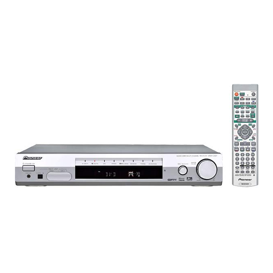
AUDIO/VIDEO MULTI-CHANNEL RECEIVER
VSX-C301-S
VSX-C301-K
THIS MANUAL IS APPLICABLE TO THE FOLLOWING MODEL(S) AND TYPE(S).
Model
Type
VSX-C301-S
MYXU
VSX-C301-K
MYXU
VSX-C301-S
NVXU
For details, refer to "Important symbols for good services".
PIONEER CORPORATION
PIONEER ELECTRONICS (USA) INC. P.O. Box 1760, Long Beach, CA 90801-1760, U.S.A.
PIONEER EUROPE NV Haven 1087, Keetberglaan 1, 9120 Melsele, Belgium
PIONEER ELECTRONICS ASIACENTRE PTE. LTD. 253 Alexandra Road, #04-01, Singapore 159936
PIONEER CORPORATION 2003
STANDBY/ON
PHONES
DIGITAL IN
Power Requirement
AC220-230V
AC220-230V
AC230V
4-1, Meguro 1-chome, Meguro-ku, Tokyo 153-8654, Japan
VSX-C301
AUDIO/VIDEO MULTI-CHANNEL RECEIVER
MASTER
2
2
AV DIRECT
DIGITAL
DTS
STEREO
PRO LOGICII
ADVANCED
PHONES
SOUND MODE
INPUT SELECTOR
VOLUME
FRONT INPUT
VIDEO
L
AUDIO R
R
DOWN
UP
VSX-C301-S
ORDER NO.
RRV2741
Remarks
T-ZZK APR. 2003 printed in Japan
Advertisement
Table of Contents

Related Manuals for Pioneer VSX-C301-S


Summary of Contents for Pioneer VSX-C301-S
- Page 1 PIONEER CORPORATION 4-1, Meguro 1-chome, Meguro-ku, Tokyo 153-8654, Japan PIONEER ELECTRONICS (USA) INC. P.O. Box 1760, Long Beach, CA 90801-1760, U.S.A. PIONEER EUROPE NV Haven 1087, Keetberglaan 1, 9120 Melsele, Belgium PIONEER ELECTRONICS ASIACENTRE PTE. LTD. 253 Alexandra Road, #04-01, Singapore 159936 PIONEER CORPORATION 2003 T-ZZK APR.
-
Page 2: Safety Information
PIONEER Service Manual. A subscription to, or additional copies Also test with plug reversed of, PIONEER Ser vice Manual may be obtained at a (Using AC adapter Earth nominal charge from PIONEER. plug as required) - Page 3 By following the instructions in this manual, be sure to apply the prescribed grease or glue to proper portions by the appropriate amount.For replacement parts or tools, the prescribed ones should be used. VSX-C301-S...
-
Page 4: Table Of Contents
7.1.2 Protection Circuit........................... 86 7.1.3 Specifications of Speaker Detection ..................... 87 7.1.4 Circuit Description..........................88 7.1.5 Troubleshooting ............................. 89 7.1.6 Timing Chart............................90 7.2 PARTS..............................94 7.2.1 IC ................................94 7.2.2 DISPLAY ............................. 101 7.3 CLEANING............................. 102 8. PANEL FACILITIES ............................103 VSX-C301-S... -
Page 5: Specifications
"DTS" and "DTS Digital Surround" are trademarks of Digital Theater Systems, Inc. Accessories • Power Cable (MYXU Type) • Remote Control Unit (ADG1154) (AXD7348) AM loop antenna FM wire antenna • Dry Cell Battery (R6P, AA) • Power Cable (NVXU Type) (ATB7009) (ADH7030) (ADG1156) (VEM1010) VSX-C301-S... -
Page 6: Exploded Views And Parts List
For the applying amount of lubricants or glue, follow the instructions in this manual. (In the case of no amount instructions, apply as you think it appropriate.) 2.1 PACKING VSX-C301-S/MYXU and VSX-C301-K/MYXU Types Only VSX-C301-S/NVXU Type Only VSX-C301-S/NVXU Type Only... - Page 7 Packing Case See Contrast table(2) (Dutch, Spanish) NSP 9 Polyethylene Bag (A4*2) See Contrast table(2) (2) CONTRAST TABLE VSX-C301-S/MYXU, VSX-C301-K/MYXU and VSX-C301-S/NVXU are constructed the same except for the follow- ing: VSX-C301-S/ VSX-C301-K/ VSX-C301-S/ Mark No. Symbol and Description MYXU...
-
Page 8: Exterior Section
2.2 EXTERIOR SECTION Refer to "2.3 INTERIOR SECTION". Refer to "2.4 FRONT PANEL SECTION". VSX-C301-S... - Page 9 • • • • • • NSP 24 Label VRW1629 > AC Inlet Assy VKP2116 (2) CONTRAST TABLE VSX-C301-S/MYXU, VSX-C301-K/MYXU and VSX-C301-S/NVXU are constructed the same except for the follow- ing: VSX-C301-S/ VSX-C301-K/ VSX-C301-S/ Mark No. Symbol and Description MYXU...
-
Page 10: Interior Section
2.3 INTERIOR SECTION VSX-C301-S... - Page 11 AEC7458 Core Stay A ANG7447 Core Stay B ANG7448 Jack Stay ANG7450 Trans Frame ANG7446 NSP 26 Under Base ANA7151 PCB Support AEC7365 PCB Mold AMR2533 NSP 29 PC Support VEC1749 Foot REC-434 Screw BBZ30P060FMC Screw BCZ40P060FNI Screw BBZ30P180FMC VSX-C301-S...
-
Page 12: Front Panel Section
2.4 FRONT PANEL SECTION VSX-C301-S... - Page 13 AAK8083 Insulator Ring AAK8091 Screw PPZ30P080FMC Rubber Foot VEB1325 VOL Ring ABH7220 (2) CONTRAST TABLE VSX-C301-S/MYXU, VSX-C301-K/MYXU and VSX-C301-S/NVXU are constructed the same except for the follow- ing: VSX-C301-S/ VSX-C301-K/ VSX-C301-S/ Mark No. Symbol and Description MYXU MYXU NVXU 5 Front Panel 301SMY Assy...
-
Page 14: Block Diagram And Schematic Diagram
3.1 BLOCK DIAGRAM 3.1.1 AUDIO BLOCK FRONT IN ASSY (3/3) FM/AM TUNER MODULE FRONT IN ASSY (1/3) SCART-1F ASSY (1/2) SCART-2F ASSY (1/2) KAWA ASSY 27 25 23 24 FRONT IN ASSY (2/3) 6 7 8 4 5 6 ASSY VSX-C301-S... - Page 15 AMP KAWA ASSY 6CH AMP ASSY AMP OUT ASSY MOTHER ASSY VSX-C301-S...
-
Page 16: Video And Power Supply Blocks
3.1.2 VIDEO AND POWER SUPPLY BLOCKS SCART-2F ASSY (2/2) SCART-1F ASSY (2/2) FRONT IN ASSY (2/3) MOTHER ASSY VSX-C301-S... - Page 17 PRIMARY ASSY MOTHER ASSY SCART-1F ASSY D2113,D2117, D2118,D2120 12V ASSY VHVL ASSY 6CH AMP ASSY DSP ASSY MOTHER ASSY VSX-C301-S...
-
Page 18: Overall Wiring Diagram
(AWX8168) 12V ASSY (AWX8170) AC POWER CORD MYXU: ADG1154 NVXU: ADG1156 AC INLET ASSY VKP2116 1/5- MOTHER ASSY (AWX8171) PRIMARY ASSY (AWX8166) 1/2- DSP ASSY (AWX8241) J4601 ADX7442 FRONT IN ASSY (AWX8219) FRONT ASSY (AWX8173) POWER SW ASSY (AWX8174) VSX-C301-S... - Page 19 Note : When ordering service parts, be sure to refer to "EXPLODED VIEWS and PARTS LIST" or "PCB PARTS LIST". AMP KAWA ASSY AMP OUT ASSY (AWX8223) (AWX8164) DC FAN MOTOR AXM7025 6CH AMP ASSY (AWM7786) DSP KAWA ASSY (AWX8167) VHVL ASSY (AWX8237) D5V ASSY (AWX8224) ENCODER ASSY (AWX8175) VSX-C301-S...
-
Page 20: Fm/Am Tuner Module
3.3 FM/AM TUNER MODULE FM/AM TUNER MODULE (AXQ7246) FM FRONT END (FM) (FM) (FM) (FM) (AM) (AM) (AM) MW RF TUNING BLOCK (FM) (AM) VSX-C301-S... - Page 21 : The power supply is shown with the marked box. (TX) : AUDIO SIGNAL ROUTE (TUNER) (AM) : AM SIGNAL ROUTE (FM) : FM SIGNAL ROUTE CN801 (AM) (TX) (FM) (TX) (TX) (TX) (FM) (FM) (TX) (AM) VSX-C301-S...
-
Page 22: Scart-1F Assy
3.4 SCART-1F ASSY CN1263 SCART-1F ASSY (AWX8168) CN2201 CN2202 VSX-C301-S... - Page 23 : VIDEO SIGNAL ROUTE (COMPOSITE) : VIDEO SIGNAL ROUTE (RGB: R) T1 PT IC2104: ANALOG AUDIO FUNCTION CN1262 CAUTION : FOR CONTINUED PROTECTION AGAINST RISK OF FIRE. REPLACE ONLY WITH SAME TYPE NO. 49102.5 FOR IC2101 AND IC2102 MFD, BY LITTELFUSE INC. VSX-C301-S...
-
Page 24: Scart-2F Assy
3.5 SCART-2F ASSY CN2102 CN2103 RGB VIDEO FUNCTION VSX-C301-S... - Page 25 CN552 SCART-2F ASSY (AWX8169) VIDEO POWER SUPPLY CN9001 BLANKING & STATUS SELECT : The power supply is shown with the marked box. : VIDEO SIGNAL ROUTE (COMPOSITE) : VIDEO SIGNAL ROUTE (RGB: R) VSX-C301-S...
-
Page 26: Mother Assy (1/5)
3.6 MOTHER ASSY (1/5) CN201 SOME FUNCTION IS ON : 0V ALL FUNCTION IS ON : 5V CN2204 : The power supply is shown with the marked box. CN551 VSX-C301-S... - Page 27 CN4203 MOTHER ASSY (AWX8171) DC DETECT: 3-4V OVERLOAD DETECT: 2-3V Short-circuit Fan and Power supply circuit: less than 2V (VH/VL) CN8012 VSX-C301-S...
-
Page 28: Mother Assy (2/5) And Dsp Kawa Assy
3.7 MOTHER ASSY (2/5) and DSP KAWA ASSY NORMAL : 0V OVERLOAD : 5V IATT ON : +12V OFF : -12V INPUT ATT A/D OVERLOAD DETECT DSP KAWA ASSY (AWX8167) CN8017 CN8003 CN8009 VSX-C301-S... - Page 29 MOTHER ASSY (AWX8171) : AUDIO SIGNAL ROUTE (ANALOG) LOW PASS FILTER : AUDIO SIGNAL ROUTE (DIGITAL) For SP CONFIG. MIX AMP : The power supply is shown with the marked box. VSX-C301-S...
-
Page 30: Mother Assy (3/5)
3.8 MOTHER ASSY (3/5) MOTHER ASSY (AWX8171) VSX-C301-S... - Page 31 : AUDIO SIGNAL ROUTE (ANALOG) VSX-C301-S...
-
Page 32: Mother Assy (4/5)
3.9 MOTHER ASSY (4/5) MOTHER ASSY (AWX8171) VSX-C301-S... - Page 33 : AUDIO SIGNAL ROUTE (ANALOG) (HP) : AUDIO SIGNAL ROUTE (HP OUT) 15dB ATT (HP) VOLUME -∞ to -15dB : 5V -14dB to 0dB : -12V MUTE ON : +3V OFF : -12V : The power supply is shown with the marked box. VSX-C301-S...
-
Page 34: Mother Assy (5/5)
NO. 491004 FOR IC203 MFD, BY LITTELFUSE INC. CAUTION : FOR CONTINUED PROTECTION AGAINST RISK OF FIRE. REPLACE ONLY WITH SAME TYPE NO. 491.630 FOR IC206 MFD, BY LITTELFUSE INC. : The power supply is shown with the marked box. VSX-C301-S... - Page 35 J6001 CN4201 VSX-C301-S...
-
Page 36: Dsp Assy (1/2)
3.11 DSP ASSY (1/2) VSX-C301-S... - Page 37 DSP ASSY (AWX8241) CN811 : The power supply is shown with the marked box. VSX-C301-S...
-
Page 38: Dsp Assy (2/2)
3.12 DSP ASSY (2/2) CN9005 VSX-C301-S... - Page 39 DSP ASSY (AWX8241) VSX-C301-S...
-
Page 40: Front In And Amp Kawa Assys
3.13 FRONT IN and AMP KAWA ASSYS FRONT IN ASSY (AWX8219) : 0V No HP : 5V (HP) (HP) J4601 ADX7442 CN1204 (HP) : AUDIO SIGNAL ROUTE (HP OUT) VSX-C301-S... - Page 41 CN203 CN1501 : AUDIO SIGNAL ROUTE (ANALOG) : The power supply is shown with the marked box. CAUTION : FOR CONTINUED PROTECTION AGAINST RISK OF FIRE. REPLACE ONLY WITH SAME TYPE NO. 491007 FOR IC4701 MFD, BY LITTELFUSE INC. VSX-C301-S...
-
Page 42: 6Ch Amp Assy
3.14 6CH AMP ASSY CN3651 to FAN Motor CN3001 (FL) (SW) (SL) Non Distortion Circuit CN3002 VSX-C301-S... - Page 43 : FL ch AUDIO SIGNAL ROUTE (SL) : SL ch AUDIO SIGNAL ROUTE : The power supply is shown with the marked box. : C ch AUDIO SIGNAL ROUTE (SW) : Refer to "7. 1. 4 Circuit Description". : SW ch AUDIO SIGNAL ROUTE VSX-C301-S...
-
Page 44: Amp Out Assy
3.15 AMP OUT ASSY AMP OUT ASSY (AWX8164) (HP) CN252 (HP) OVERLOAD DETECT (HP) SP DETECT DC DETECT : AUDIO SIGNAL ROUTE (ANALOG) (HP) : AUDIO SIGNAL ROUTE (HP OUT) : The power supply is shown with the marked box. VSX-C301-S... - Page 45 VSX-C301-S...
-
Page 46: Encoder, Front And Power Sw Assys
3.16 ENCODER, FRONT and POWER SW ASSYS ENCODER ASSY (AWX8175) FRONT ASSY (AWX8173) J4401 DE010WE0 ENCODER ASSY S4401 : INPUT SELECTOR S4402 : MASTER VOLUME Display Microcomputer VSX-C301-S... - Page 47 POWER SW ASSY S4501 : STANDBY/ON LED1 LED2 LED3 LED4 LED5 LED6 LED7 LED8 DOLBY DOLBY SOUND STEREO ADVANCED PHONES DIRECT DIGITAL PROLOGIC MODE SW-ON : 0V OTHERS : 5V : The power supply is shown with the marked box. VSX-C301-S...
-
Page 48: Primary, D5V, 12V And Vhvl Assys
3.17 PRIMARY, D5V, 12V and VHVL ASSYS T1 POWER TRANSFORMER ATS7346 CN202 CN2108 CN203 D5V ASSY (AWX8224) 12V ASSY (AWX8170) VSX-C301-S... - Page 49 PRIMARY ASSY (AWX8166) B2P3-VH NEUTRAL LIVE AC IN VHVL ASSY (AWX8237) • NOTE FOR FUSE REPLACEMENT FOR CONTINUED PROTECTION AGAINST RISK OF FIRE. CAUTION - REPLACE WITH SAME TYPE AND RATINGS ONLY. VSX-C301-S...
-
Page 50: Pcb Connection Diagram
Symbol In PCB Symbol In Schematic Part Name Diagrams Diagrams C E B Capacitor Connector Transistor B C E SIDE A Transistor with resistor B C E Field effect SIDE B P.C.Board Chip Part transistor Resistor array 3-terminal regulator VSX-C301-S... -
Page 51: Fm/Am Tuner Module
Printed T-meter Side C211 IC201 CPSC-BS1 94V-0 R221 W107 +10V W108 CN201 W103 BLACK (ANP7458-A) CN201 IC201 Q202 IC202 CN801 SIDE B SIDE B FM/AM TUNER MODULE CN201 CN201 IC201 IC202 (ANP7458-A) Q602 Q201 IC201 Q601 IC202 Q203 Q204 VSX-C301-S... -
Page 52: Scart-1F And 12V Assys
4.2 SCART-1F and 12V ASSYS SIDE A CN2201 SCART-1F ASSY CN2102 JA2104 JA2105 D.C. C2113 F.C. CN2102 W648 W655 49102.5 CN2108 C2170 R2147 C2168 C2169 W612 W613 J620 12V ASSY CN2106 C603 W602 CN2106 C604 CN1262 IC2102 IC2103 (ANP7451-B) IC601 IC602 VSX-C301-S... - Page 53 GNDA VIDEOoutR GNDA TVinR GNDA VIDEOinR GNDA VIDEOinL C2156 GNDA TVinL W647 GNDA C2131 VIDEOoutL PYKC F4 W637 C2130 W625 AWX8168- -U W624 AWX8233- -U W623 W638 C2160 W611 CN2106 C2163 W610 C2161 CN2104 SCART-1F ASS'Y (ANP7451-B) CN2104 CN1263 VSX-C301-S...
- Page 54 C2108 C2107 C2106 R2142 L2101 R2140 Q2104 IC2104 C2110 D2129 R2106 C2124 R2182 R2181 R2124 CN2106 AWX8168- -U AWX8233- -U CN2104 0 1 2 3 4 5 6 7 8 9 0 1 2 3 R2185 R2186 CN2104 CN2106 VSX-C301-S...
- Page 55 SIDE B CN2102 C2178 C2172 C2177 C2174 R2114 CN2102 IC2104 D2127 12V ASSY CN2106 L2102 L2103 (ANP7451-B) CN2106 (ANP7451-B) VSX-C301-S...
-
Page 56: Scart-2F Assy
4.3 SCART-2F ASSY SIDE A SCART-2F ASSY JA2203 JA2204 JA2201 VIDEO C2211 W711 W717 W710 W720 CN2103 CN2201 W741 W742 CN2204 W786 CN2204 CN9001 VSX-C301-S... - Page 57 SIDE A Q2203 Q2204 JA2201 JA2202 J2201 W710 PYKC F4 W701 SCART-2F ASS'Y W709 AWX8169- -U J2201 CN2102 CN2201 W724 CN552 W725 W751 W747 W749 W748 W786 (ANP7451-B) VSX-C301-S...
- Page 58 SIDE B Q2201 Q2207 SCART-2F ASSY R2219 C2201 C2216 Q2207 C2254 J2201 C2202 C2206 C2205 C2204 R2253 C2217 C2218 C2221 PYKC F4 R2213 J2201 CN2201 C2231 D2219 D2221 R2225 D2220 D2239 VSX-C301-S...
- Page 59 C2206 C2205 R2241 C2204 R2215 GREEN IC2202 BLUE IC2201 BLANKING status DVRoutR TVinR DVRinR CN2201 DVRinL C2227 C2226 TVinL DVRoutL R2208 R2221 R2222 C2230 C2231 D2219 D2240 IC2205 R2225 D2216 R2224 D2220 R2267 Q2202 CN2204 D2239 R2260 (ANP7451-B) CN2204 VSX-C301-S...
-
Page 60: Mother, Dsp Kawa And D5V Assys
CN1501 CN1501 CN4701 CN2104 Q1301 IC206 IC203 IC205 IC4651 Q1501 Q1502 Q1505 Q1506 Q1510 IC1302 IC210 IC9002 Q1264 IC1501 IC1502 IC1503 IC1504 IC1304 IC1303 Q1102 Q1503 Q1504 Q1508 Q1511 Q1513 IC1241 IC1301 Q1263 Q1101 IC1221 Q1507 Q1514 Q1266 Q1265 VSX-C301-S... - Page 61 SL O C1269 SW O C1161 CN201 SB O CN801 (ANP7452-A) CN551 CN2106 CN1262 KN1201 (ANP7452-A) CN1263 CN9001 CN2204 2104 IC9001 Q1264 Q9009 Q9008 Q9011 Q9010 Q1104 Q1103 Q1102 Q9003 IC1101-IC1104 Q1263 Q1101 IC1105 Q9006 Q9007 Q1266 Q1265 IC1261 Q9005 VSX-C301-S...
- Page 62 SB O GNDC FR O VCOMG FL O CN801 SR O GNDC SL O SW O R1263 C1262 R808 C1261 R1264 R1262 SB O R1286 (ANP7452-A) CN9001 CN1262 CN1263 CN1262 CN9001 CN1263 Q4651 Q4652 Q801 Q9004 Q9001 Q1262 Q1261 VSX-C301-S...
- Page 63 MENT DES FUSIBLES IC206 N'UTILISER QUE LA REFERENCE 491.630 DE CHEZ LITTELFUSE INC.. C1365 C1364 R1234 R1233 R1230 C9000 R1529 R1242 R1531 R1226 C1215 R1223 C1214 CN1501 R1197 C1185 (ANP7452-A) R1193 CN1501 D1211 C1212 R1263 C1261 1263 Q4653 Q1512 VSX-C301-S...
-
Page 64: Dsp Assy
4.5 DSP ASSY SIDE A SIDE A DSP ASSY CN1811 IC8201 CN1264 Q8504 IC8702 IC8301 Q8341 CN1813 IC8701 Q8501 IC8501 CN9005 IC8502 IC8603 IC8601 (ANP7465-A) VSX-C301-S... - Page 65 C8544 R8523 C8520 R8309 C8518 C8542 R8310 C8521 R8311 C8540 R8528 R8312 R8313 R8529 R8314 C8539 R8326 C8538 C8529 C8534 C8535 R8537 L8502 R8603 L8602 C8531 R8801 R8812 R8811 R8813 R8602 C8014 IC8602 C8013 C8606 C8605 C8608 C8607 (ANP7465-A) VSX-C301-S...
-
Page 66: Front In Assy
J4602 FRONT IN ASS'Y HCMK-P3X CAUTION AWX8219 CN4102 C4108 REPLACE WITH SAME TYPE NO. KN4101 J4601 Production Code 491010 FOR IC201,IC202 MFD. BY LITTELFUSE INC. C4101 CN4102 (ANP7453-B) CN1204 SIDE B SIDE B FRONT IN ASSY CN4102 CN4102 (ANP7453-B) VSX-C301-S... -
Page 67: Amp Kawa Assy
CN4701 CN4705 CN4706 ATTENTION EN CAS DE REMPLACEMENT FUSIBLES IC4701 N'UTILISER QUE LA REFERENCE 491007 DE CHEZ LITTELFUSE SLOUT SLOUT INC. SROUT SROUT COUT COUT SBOUT SBOUT GNDS FLOUT FLOUT GNDP PYKC F4 GNDP FROUT FROUT (ANP7451-B) CN4703 J4702 VSX-C301-S... -
Page 68: 6Ch Amp Assy
W151 IC3301 W179 R3322 D3324 D3326 D3393 R3328 R3318 W180 D3328 D3322 Q3383 W181 R3320 W182 GNDP C3308 R3387 C3508 D3394 R3518 C3324 W200 R3520 Q3384 W201 D3387 W155 FROUT D3385 R3388 D3386 W156 W203 D3388 W157 (ANP7459-A) CN3651 VSX-C301-S... - Page 69 R3534 R3389 R3540 Q3534 R3510 SWOUT Q3534 Q3532 C3504 SWOUT C3506 R3512 GNDS C3510 FLOUT D3582 R3506 FLOUT D3544 R3538 GNDP R3544 GNDP Q3381 FROUT Q3381 FROUT R3592 R3532 R3381 FROUT R3390 R3382 Q3382 Q3382 FAN SIDE (ANP7459-A) CN3651 VSX-C301-S...
-
Page 70: Amp Out Assy
4.9 AMP OUT ASSY SIDE A SIDE A AMP OUT ASSY JA301 W111 CN252 W127 Q307 Q307 19.FROUT FROUT FLOUT FLOUT GNDS COUT R324 COUT SROUT SROUT SLOUT SLOUT GNDREG GNDREG V+15 1.ACB CN4703 CN301 (ANP7451-B) CN9010 VSX-C301-S... - Page 71 R307 Q314 D323 Q301 Q319 Q318 19.FROUT FROUT FLOUT FLOUT GNDS Q305 C325 COUT COUT SROUT SROUT SLOUT R325 SLOUT D313 Q309 GNDREG R344 GNDREG V+15 Q313 1.ACB R343 Q317 R350 Q310 R348 R347 Q312 R361 R360 (ANP7451-B) CN301 VSX-C301-S...
-
Page 72: Encoder, Front And Power Sw Assys
4.10 ENCODER, FRONT and POWER SW ASSYS SIDE A CN9006 FRONT ASSY CN4203 CONTACT SIDE D4205 D4203 D4204 D4206 CN4203 AWX8199 AWX8173 AWX8205 AWX8214 X4201 AWX8202 AWX8196 AWX8211 AWX8217 4202 FRONT ASS'Y 4501 4501 J4201A POWER SW ASS'Y AWX8174 AWX8206 HCMK-P3X (ANP7453-B) POWER SW ASSY VSX-C301-S... - Page 73 SIDE A CN207 CN4201 CONTACT SIDE D4210 D4209 D4206 D4207 D4208 CN4201 AWX8214 AWX8217 C4218 4201 L4201 V4301 HCMK-P3X (ANP7453-B) 4401 ENCODER ASS'Y HCMK-P3X AWX8175 S4402 ENCODER ASSY (ANP7453-B) VSX-C301-S...
- Page 74 R4216 R4224 R4215 R4203 C4215 C4216 R4241 R4214 FENCA FENCB R4213 GNDU R4212 VENCB VENCA R4243 R4211 R4244 HCMK-P3X C4217 IC4201 Q4208 Q4206 4401 HCMK-P3X R4404 R4403 C4401 C4404 R4402 C4405 R4401 C4406 ENCORDER ASSY AWX8175 (ANP7453-B) ENCODER ASSY VSX-C301-S...
- Page 75 R4231 R4230 C4229 R4229 D4211 Q4201 R4210 R4216 R4215 Q4202 Q4211 Q4210 AWX8196 AWX8173 AWX8202 AWX8199 AWX8205 AWX8211 AWX8214 FRONT ASSY AWX8217 (ANP7453-B) Q4204 Q4203 Q4210 Q4202 Q4201 4501 4501 POWER SW ASSY AWX8174 AWX8206 (ANP7453-B) POWER SW ASSY VSX-C301-S...
-
Page 76: Primary Assy
PRIMARY ASSY CN502 CN501 LIVE NEUTRAL CN502 PRIMARY C502 J2201 SECONDARY TVMUTE C556 T501 CN551 (ANP7451-B) J9002 SIDE B SIDE B PRIMARY ASSY CN551 D557 PRIMARY ASS'Y AWX8166- -U AWX8230- -U Q551 Q552 Q553 Q554 CN502 (ANP7451-B) CN502 CN501 VSX-C301-S... -
Page 77: Vhvl Assy
IC201 491010 J301 IC201 W204 2.GND 1.ACB GNDP IC202 6.VL+ W202 VHVL ASS'Y AWX8234- -U BOND PYKC F4 AWX8237- -U W201 (ANP7451-B) CN201 CN206 T1 PT J4702 SIDE B SIDE B VHVL ASSY CN206 CN201 PYKC F4 CN252 (ANP7451-B) VSX-C301-S... -
Page 78: Pcb Parts List
0 SHIELD CASE T(MTL) ANK7072 COILS AND FILTERS 0 SHIELD CASE B(MTL) ANK7073 L201 ATE7003 X201 CRYSTAL RESONATOR ASS1093 F202 ATF-107 (7.2MHz) F201 ATF-119 F601 ATF7025 FM FRONT END AXF7005 F203 ATF7026 AM RF TUNING BLOCK AXX7072 L602 LAU2R2J VSX-C301-S... - Page 79 2SC2412K SEMICONDUCTORS Q1261,Q1262,Q1301,Q1503,Q1504 2SC3326 IC2201-IC2203 BA7613F Q1507,Q1508,Q1511,Q4653 2SC3326 IC2206 BU4052BCFV IC2205 NJM2296M Q1103,Q1104 2SK208 IC2207 NJM4558MD Q1101,Q1263,Q1266,Q9004 DTA124EK Q2204 2SA1515 Q9008-Q9010 DTA124EK Q1102,Q1265 DTC124EK Q2205 2SC4081 Q1264,Q4652,Q9001 DTC143EK Q2203 2SC5174P Q2201 DTA124EUA Q9011 DTC143TK Q2202 DTC124EUA > D204 1SR154-400 VSX-C301-S...
- Page 80 CKSRYB103K50 IC8201 AK4114VQ IC8401 AK4529VQ C802,C804,C9001,C9004,C9008 CKSRYB103K50 IC8501 DSPD56367PV150 C9021 CKSRYB103K50 IC8901 NJM2391DL1-33 C1266 CKSRYB104K16 IC8902 NJU7223DL1-18 C1187,C1188,C1237-C1240,C1271 CKSRYB104K25 C215,C216 CKSRYB104K25 IC8701 TC74LVX244FT IC8702 TC74VHCT244AFT C1272,C803,C805,C9006 CKSRYB105K10 IC8502 TC7WU04FU C1144 CKSRYB223K50 Q8504 UMD2N C1198 CKSRYB471K50 Q8503 UN5112 C1133,C1134,C1153,C1154 CKSRYB472K50 VSX-C301-S...
- Page 81 D3381,D3382,D3481,D3482 DAN217 > D3581,D3582 DAN217 FRONT-IN ASSY D3389,D3390 MTZJ10C CAPACITORS > MTZJ15C C4103,C4104 CCSRCH101J50 D3393,D3394 MTZJ18B/C > C4107,C4111,C4122 CCSRCH471J50 MTZJ18C C4108 CEAL470M16 D3385,D3386 MTZJ36A C4105,C4109,C4117,C4124 CKSRYB103K50 C4102,C4106,C4110,C4123 CKSRYB104K25 D105,D106,D3658 UDZS7.5B TH111 NCP18WF104J03RB C4112,C4113 CKSRYB223K50 CAPACITORS C4120,C4121 CKSRYF105Z10 C3305,C3306,C3405,C3406 CCSRCH221J50 VSX-C301-S...
- Page 82 SLR-343YC D311-D314,D316,D317 1SS355 D322-D327 1SS355 COILS AND FILTERS D319 DAN202K D303,D310,D315 DAP202K L4201 LFEA2R2J CAPACITORS D318 UDZS5.1B C4203 CEJQ221M6R3 COILS AND FILTERS C4205 CEJQ470M10 L301,L302,L304-L306 ATH-059 C4210-C4213,C4228 CKSRYB102K50 C4201,C4202,C4204,C4215-C4217 CKSRYB103K50 SWITCHES AND RELAYS C4208,C4245 CKSRYB104K25 RY301-RY304 ASR7008 C4220-C4227 CKSRYB473K50 VSX-C301-S...
- Page 83 CEAT102M25 C551 CEAT470M25 C553-C555 CKSRYB103K50 RESISTORS R551 RD1/2VM270J Other Resistors RS1/16S###J OTHERS H501,H502 FUSE CLIP AKR7001 CN552 2P CONNECTOR POST B2B-PH-K CN502 2P-VH CONNECTOR B2P3-VH CN551 4P CONNECTOR B4B-PH-K > CN501 AC CORD SOCKET RKP1751 KN501 WRAPPING TERMINAL VNF1084 VSX-C301-S...
-
Page 84: Adjustment
Pin 21 and Pin 23 of IC201 (Test point Vtm) Adjustment gets within 0 ± 50mV. PRODUCT MPX SG FM SG Voltmeter FM75Ω antenna terminal Fig.1 Adjustment Wiring Diagram FM/AM TUNER MODULE L201 IC201 pin 21 pin 23 SIDE B Fig.2 Adjustment Point VSX-C301-S... -
Page 85: General Information
Note : Test mode of No. 1-12 is Preset ID 150. For the FL (international) model only, when the code is received, Test mode of No. 13, 14 is Preset ID 156. 9K and 10K can be switched. When the code is first received, 10K is selected. VSX-C301-S... -
Page 86: Protection Circuit
Fan stop XPROTECT port (A/D) Detection method 0.4 Vdd or less Detection start time 1.0 sec after Mute: On Process Speaker Relay: Off Shifting to STBY Display No display Recovery Hold the STANDBY key pressed for 10 sec. Remarks VSX-C301-S... -
Page 87: Specifications Of Speaker Detection
5 Detection circuit for the center speaker Check signal from microcomputer Detection of the center speaker 10 kΩ Detection signal to microcomputer 47 kΩ mute Mute About 8Ω Satellite speakers may be connected. POWER AMP (IC3401) VSX-C301-S... -
Page 88: Circuit Description
→ The microcomputer detects the XPROTECT level and shuts the power to the unit off. (3) When VD+5 is short-circuited The level of the XPROTECT line becomes low. The microcomputer detects the XPROTECT level and shuts the power to the unit off. VSX-C301-S... -
Page 89: Troubleshooting
• Check power voltage of IC1501-1503. Check Pins 15 and 17-21 • Check AMUTE. of CN3002. Check Pins 3, 7, 10, 14, • Check power voltage and periphery of IC3301 and IC3401. 18, 22 of CN3001. Check SP OUT. VSX-C301-S... -
Page 90: Timing Chart
7.1.6 Timing Chart VSX-C301-S... - Page 91 (IC1211 : NJU7313AM) VIDEO system mute (IC2205 : NJM2296) mute TUNER (IC202 : LC72131) E-VOLUME mute (IC1221 : BD3814FV) (IC8501 : DSPD56367PV150) DIR/CODEC (IC8201 : AK4114VQ / IC8401 : AK4628VQ) SPEAKER relay (port) OVERLOAD DETECT AMP ERROR DETECT FAN ERROR DETECT VSX-C301-S...
- Page 92 VSX-C301-S...
- Page 93 VSX-C301-S...
-
Page 94: Parts
P33/A11 MVRATT P77/TA3IN P34/A12 RY-AC P76/TA3OUT P35/A13 HP DET P75/TA2IN/W P36/A14 RY_SP 1394 RST P74/TA2OUT/W P37/A15 RY_HP P40/A16 1394 CS P73/CTS2/RTS2/TA1IN/V MCACC P41/A17 1394 CK P72/CLK2/TA1OUT/V AMUTE P71/RxD2/SCL 1394 DO P42/A18 GAIN_SEL /TA0IN/TB5IN 1394 DI P70/TXD2/SDA P43/A19 IATT /TA0OUT VSX-C301-S... - Page 95 Data input signal for communication with DIR/DAC P50/WRL/WR DIR CS Chip select signal for communication with DIR/DAC P47/CS3 DIR codec over flag P46/CS2 DIR CDC RST Reset signal for DIR codec P45/CS1 DIR ERR Lock/unlock signal P44/CS0 XTL0 DIR X'tal change VSX-C301-S...
- Page 96 P103/AN3 "L" fixed P102/AN2 SIMUKE1 lnput 1 to switch region P101/AN1 XPROTECT Ptotection circuit detect for amp. module AVSS AVSS Connect to VSS P100/AN0 "L" fixed VREF VREF Connect to VCC AVcc AVCC Connect to VCC P97/ADTRG/SIN4 "L" fixed VSX-C301-S...
- Page 97 P20/SCK3 C-MOS P-CH FIP31/P37 LED8 DISP EN P00/INTP0 C-MOS P-CH FIP32/P40 NC(PD)(MULTIROOM SRIN) P01/INTP1 C-MOS P-CH FIP33/P41 LED7 SR IN P02/T1 C-MOS P-CH FIP34/P42 LED6 AVSS P-CH FIP35/P43 LED5 ANI3 COPM P-CH FIP36/P44 LED4 LED3 ANI2 COMP P-CH FIP37/P45 VSX-C301-S...
- Page 98 VOLUME JOG1(-) P60/FIP48 EN A VOLUME JOG1(+) P57/FIP47 P56/FIP46 TEST Test mode input for checker P55/FIP45 AV DIRECT P54/FIP44 P53/FIP43 P52/FIP42 1W WUP Output wakeup signal to main u-com P51/FIP41 P50/FIP40 P47/FIP39 LED1 LED output P46/FIP38 LED2 LED output VSX-C301-S...
- Page 99 Display FIP18 Display FIP17 Display FIP16 Display FIP15 Display FIP14 Display FIP13 Display FIP12 Display FIP11 Display FIP10 Display FIP9 Display FIP8 Display FIP7 Display FIP6 Display FIP5 Display FIP4 Display FIP3 Display FIP2 Display FIP1 Display FIP0 Display VSX-C301-S...
- Page 100 • Video Signal Switcher for VTR, TV Block Diagram VOUT MUTE 75Ω CTLA LOGIC CTLB Pin Function Pin Name Function Signal input CTLA Control input CTLB Control input Signal input − Ground Signal input − Power supply VOUT Signal output VSX-C301-S...
-
Page 101: Display
7.2.2 DISPLAY AAV7093 (FRONT ASSY : V4301) • FL Display Pin Assignment Grid Assignment Segment Designation Pin Connection VSX-C301-S... -
Page 102: Cleaning
Anode Connection 7.3 CLEANING Before shipping out the product, be sure to clean the following positions by using the prescribed cleaning tools: Position to be cleaned Cleaning tools Fans Cleaning paper : GED-008 VSX-C301-S... -
Page 103: Panel Facilities
2 channel (stereo) source. ADVANCED indicator Lights when one of the Advanced Surround modes is active. PHONES indicator Lights when phones surround mode is active. SOUND MODE indicator Lights when one of the Sound Modes is active. VSX-C301-S... - Page 104 Lights when the Virtual Surround Back effect is on. 11 Volume level indicator 7 OVER Indicates the volume level in dB. Lights when the input signal is too high, risking distortion. Use the input attenuator to reduce the level. VSX-C301-S...
- Page 105 3 CONTROL IN jack / CONTROL OUT jack any other input, that signal is output from the VIDEO IN/OUT AV Use to link Pioneer components together to enable all components connector. in the chain to use just one remote control sensor.
- Page 106 Press to select the AUTO (default) sound for the current source (stereo, Dolby Digital, DTS, etc.) and switch off all other sound processing. STEREO RECEIVER Press to hear the current source in stereo. SURROUND Use to select a SURROUND mode for the current source. VSX-C301-S...
- Page 107 FRONT inputs. Input/control mode Preset Component select button code (manufacturer) 12 MASTER VOLUME DVD (Pioneer) Use to adjust the volume. STB (Pioneer) 13 ROOM SETUP DVR/TV DVD recorder Use to select a preset room setup. (Pioneer) 14 SYSTEM SETUP...
- Page 108 Subwoofer: 0 dB AV Direct setting MANUAL Auto Input Select MANUAL setting Room Setup M / MID • The default settings for the remote control to control other components can be found in Using the remote control with other components. VSX-C301-S...