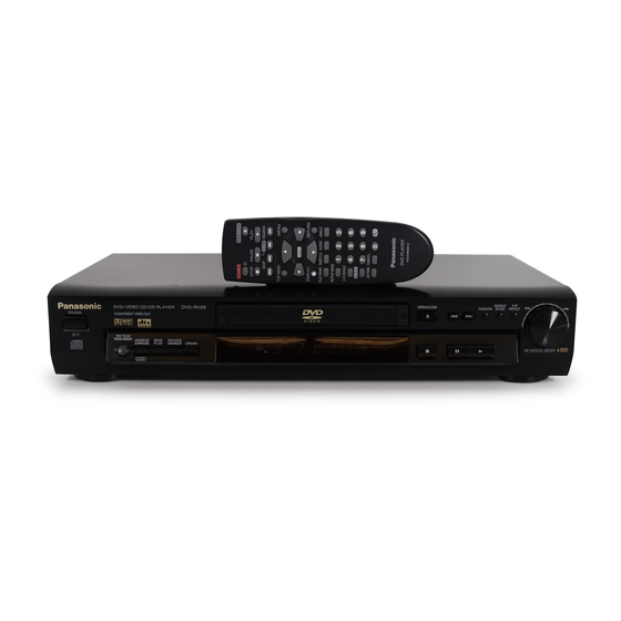
Panasonic DVD-RV26 Service Manual
Hide thumbs
Also See for DVD-RV26:
- Operating instructions manual (36 pages) ,
- Operating instructions manual (36 pages) ,
- Operating instructions manual (36 pages)
Table of Contents
Advertisement
Quick Links
Advertisement
Table of Contents

Related Manuals for Panasonic DVD-RV26


Summary of Contents for Panasonic DVD-RV26
- Page 1 ORDER NO. ODSD010308A1 DVD Player DVD-RV26 Colour (K).......Black Type Area U......U.S.A.. Please file and use this manual together with the service manual for Model No. DVD-RV31U-K, Order No. ODSD010203C1. SPECIFICATIONS Specifications...
- Page 2 Power supply: AC120 V, 60 Hz 14 W Power consumption: Dimensions: 430 (W)×247 (D)×82 (H) mm (excluding protrusions) Mass: 2.6 kg (5.7 lb.) Signal system: NTSC Operating temperature range: +5 to +35°C (+41 to +95°F) Operating humidity range: 5-90 % RH (no condensation) Discs played: (1) DVD-Video disc (2) Compact disc (CD-DA, Video CD)
- Page 3 PRoutput level: 0.7 Vp-p (75 Output terminal: Pin jack (Y: green, PB: blue, PR: red) Audio output: Output level: 2 Vrms (1 kHz, 0 dB, 10K load impedance) Output terminal: 5.1ch discrete output Pin jack (1 system) (5.1ch): Subwoofer output: Pin jack (1 system) Audio signal output characteristics: (1) Frequency response:...
- Page 4 Components identified by mark have special characteristics important for safety. Furthermore, special parts which have purposes of fire-retardant (resistors), high-quality sound (capacitors), low-noise (resistors), etc. are used. *When replacing any of components, be sure to use only manufactureris specified parts shown in the parts list.
- Page 5 ORDER NO.ODSD010307C2 DVD Player DVD-RV31 / DVD-RV41 Colour (S).......Silver Type (K).......Black Type (RV31 Only) Area E......Europe EB.......Great Britain EG.......Germany and Poland, etc. SPECIFICATIONS Specifications...
- Page 6 Power supply: AC220-240 V, 50 Hz 14 W Power consumption: Dimensions: 430 (W)×247 (D)×82 (H) mm (excluding protrusions) Mass: 2.6 kg Operating temperature range: +5 to +35°C Operating humidity range: 5-90 % RH (no condensation) Discs played: DVD-Video Compact disc (CD-DA, Video CD-R/CD-W (CD-DA, VIdeo CD format discs) Signal system:...
-
Page 7: Safety Precautions
98 dB CD audio: (4) Total harmonic distortion: 0.0025 % CD audio: Digital audio output: Optical digital output: Optical terminal Pickup Wave length: 658 nm/790 nm Laser power: CLASS 2a/CLASS 1 NORSK Pickup 658 nm/790 nm B lgelende: Laser-styrke: lngen farlig str lning sendes ut KLASSE 2a/ KLASS E 1 Power consumption in standby mode:... -
Page 8: Prevention Of Electro Static Discharge
the plug. 2. Measure the resistance value, with an ohmmeter, between the jumpered AC plug and each exposed metallic cabinet part on the equipment such as screwheads, connectors, control shafts, etc. When the exposed metallic part has a return path to thechassis, the reading should be between 1M and 5.2M . - Page 9 DEVICES Some semiconductor (solid state) devices can be damaged easily by static electricity. Such components commonly are called Electrostatically Sensitive (ES) Devices. Examples of typical ES devices are integrated circuits and some field-effect transistorsand semiconductor "chip" components. The following techniques should be used to help reduce the incidence of component damage caused by electro static discharge (ESD).
-
Page 10: Precaution Of Laser Diode
3. Precaution of Laser Diode 4. General Description 4.1. Operating instructions 5. Disassembling the Casing and Checking P.C.B.s 5.1. Dissasembly Procedure... -
Page 11: Top Cover
5.2. Caseing Parts and P.C.B. Positions 5.3. Top Cover 1. Unscrew the screws. - Page 12 5.4. Tray 1. Pull the tray out of the mechanism unit. Remove the gear and install it onto a screwdriver to make a gear jig. 2. Insert the gear jig into the tray open/close hole. 3. Turn the gear jig counterclockwise to open the tray. 4.
- Page 13 5.5. Front Panel 1. Release the tabs. 2. Remove the connectors. 5.6. Mechanism Unit 1. Unscrew the screws. 2. Remove the connectors.
- Page 14 3. Pull out the mechanism unit vertically. 5.7. Terminal P.C.B. 1. Unscrew the screws. 2. Remove the solders. 3. Remove the connectors. 5.8. Module P.C.B. 1. Unscrew the screws. 2. Remove the connectors.
- Page 15 3. Press each tab with the nipper to pull out the module PCB vertically. 5.9. Front-1 P.C.B., Front-2 P.C.B., and Front-3 P.C.B. 1. Unscrew the screws. 2. Release the tabs. 5.10. Rear panel 1. Unscrew the screws 2. Release the tabs.
- Page 16 5.11. Scart P.C.B. 1. Remove the connector. 5.12. Mother P.C.B. 1. Unscrew the screws.
-
Page 17: Servicing Position
5.13. Servicing Position 5.13.1. Servicing position of the Module P.C.B. 5.13.2. Servicing position of the Terminal P.C.B. -
Page 18: Prevention Of Static Electricity Discharge
5.13.3. List of the Extention Cables 6. PREVENTION OF STATIC ELECTRICITY DISCHARGE The laser diode in the traverse unit (optical pickup) may brake down due to static electricity of clothes or human body. Use due caution to electrostatic breakdown when servicing and handling the laser diode. -
Page 19: Optical Pickup Self-Diagnosis And Replacement Procedure
during transportation and before installation, the both ends of the laser diode are short-circuited. After replacing the parts with new ones, remove the short circuit accordingto the correct procedure. (See this Technical Guide.) 2. Do not use a tester to check the laser diode for the optical pickup. Failure to do so will damage the laser diode due to the power supply in the tester. -
Page 20: Cautions To Be Used Before Replacing The Optical Pickup Unit And Spindle Motor Assembly
7.2. Cautions to Be Used Before Replacing the Optical Pickup Unit and Spindle Motor Assembly Before replacing the optical pickup unit and spindle motor assembly, check the total using hours for each of them. The checking method is as follows:... - Page 21 Cautions to be taken when replacing the optical pickup The optical pickup may break down due to the static electricity of human body. Take proper protection measures against static electricity before repairing the parts around the optical pickup. (See the page describing the PREVENTION OF STATIC ELECTRICITYDISCHARGE.) 1.
-
Page 22: Self-Diagnosis Function And Service Modes
8. SELF-DIAGNOSIS FUNCTION AND SERVICE MODES 8.1. Self-diagnosis Function and Service Modes 8.2. Service mode table Pressing various button combinations on the player and remote control unit can activate the service modes. -
Page 24: Servo Process Flow
8.3. Servo Process Flow... - Page 25 8.4. Servo Process Display Mode 8.5. ADSC Internal Ram Data Display...
-
Page 26: Sales Demonstration Lock Function
8.6. Sales demonstration lock function This function prevents discs from being lost when the unit is used for sales demonstrations by disabling the disc eject function. "LOCKED" is displayed on the unit, and ordinary operation is disabled. 8.6.1. Setting The sales demonstration lock is set by simultaneously pressing STOP button on the player and POWER button on the remote control unit. -
Page 27: Handling After Completing Repairs
8.8. Handling After Completing Repairs Use the following procedure after completing repairs. 8.8.1. Method Confirm that the power is turned on: 1. Press the "OPEN/CLOSE" button to close the tray. 2. Press the "POWER" button to turn off the power. 3. - Page 28 9.2. Terminal P.C.B. 1. Unscrew the screws. 2. Remove the solders. 3. Remove the connectors.
- Page 29 9.3. Clamp Plate Unit 1. Spread the stopper with hand to slide the tabs and remove the clamp plate unit. 9.4. Tray 1. Lift the tray.
- Page 30 9.5. Traverse Block 1. Lift the traverse block while spreading the hook of the mechanical chassis unit. 2. Disengage the tabs from the holes of the mechanical chassis unit. 9.6. Traverse Gear 1. Disengage the tabs from the traverse gear. 2.
-
Page 31: Optical Pickup Unit
9.7. Optical Pickup Unit 1. Unscrew the screws. 2. Remove the spring holders and the springs. 3. Pull out the drive shaft and guide shaft. - Page 32 9.7.1. Precautions in optical pickup replacement The optical pickup can be damaged by static electricity from you body. Be sure to take static electricity countermeasures when working around the optical pickup. (Refer to the related page in this Manual about the countermeasures.) 1.
-
Page 33: Disassembling The Middle Chassis
9.8. Disassembling the Middle Chassis 1. Remove the holder pins. 2. Remove the tab. 3. It lifts while pulling it in the direction of the arrow. 9.9. Disassembling the Traverse Gear A 1. Remove the traverse gear A. -
Page 34: Adjustment Procedures
9.10. Disassembling the Spindle Motor Unit 1. Remove the floating rubbers. 10. ADJUSTMENT PROCEDURES 10.1. Service Tools and Equipment Application Name Number Tilt DVD test disc DVDT-S15 or DVDT-S01 adjustment Hex wrench Inspection Extension cable (module P.C.B. to mother JGS0098 (DVD-RV41 only) P.C.B.) Extension cable (module P.C.B. -
Page 35: Optical Adjustment
10.2.1. Important points in optical adjustment - Before starting optical adjustment, be sure to take anti-static measures. - Optical pickup tilt adjustment is needed after replacement of the following components. 1. Optical pickup unit 2. Spindle motor unit 3. Optical pickup peripheral parts (such as rail) Notes Adjustment is generally unnecessary after replacing other parts of the traverse unit. - Page 36 10.4.1.1. Adjustment procedure 1. While pressing PAUSE and OPEN/CLOSE buttons on the main unit, press "5" on the remote control unit. 2. Confirm that "J_xxx_yyy_zz" is shown on the front display. For your information: "yyy" and "zz" shown to the right have nothing to do with the jitter value. "yyy" is the error counter, while "zz"...
- Page 37 10.4.1.3. Check after adjustment Play test disc or any other disc to make sure there is no picture degradation in the inner, middle and outer peripheries, and no audio skipping. After adjustment is finished, lock each adjustment screw in position using screw lock. 10.4.1.4.
-
Page 38: Electrical Confirmation
11. Electrical Confirmation 11.1. Video Output (Luminance Signal) Confirmation Do this confirmation after replacing a P.C.B. Measurement point Mode Disc Video output terminal Color bar 75% DVDT-S15 PLAY (Title 46):DVDT -S15 DVDT-S01 PLAY (Title 12):DVDT -S01 Measuring equipment, tools Confirmation value Screwdriver, Oscilloscope 1000mVp-p±30mV 200mV/div, 10... -
Page 39: Video Output (Chrominance Signal) Confirmation
11.2. Video Output (Chrominance Signal) Confirmation Do this confirmation after replacing a P.C.B. Measurement point Mode Disc Video output terminal Color bar 75% DVDT-S15 PLAY (Title 46):DVDT -S15 DVDT-S01 PLAY (Title 12):DVDT -S01 Measuring equipment, tools Confirmation value Screwdriver,Oscilloscope 658mVp-p±30mV 200mV/div, 10 sec/div Purpose: To maintain video signal output compatibility. - Page 40 INITIAL/LOGO ABBREVIATIONS A0~UP ADDRESS ACLK AUDIO CLOCK AD0~UP ADDRESS BUS ADATA AUDIO PES PACKET DATA ADDRESS LATCH ENABLE AMUTE AUDIO MUTE AREQ AUDIO PES PACKET REQUEST AUDIO RF SERVO AMP INVERTED INPUT SERVO AMPOUTPUT ASYNC AUDIO WORD DISTINCTION SYNC BIT CLOCK (PCM) BCKIN BIT CLOCK INPUT BLACK DROP OUT...
- Page 41 INITIAL/LOGO ABBREVIATIONS ERROR TORQUE CONTROL ERROR TORQUE CONTROL REFERENCE ENCSEL ENCODER SELECT ETMCLK EXTERNAL M CLOCK (81MHz/ ETSCLK 40.5MHz) EXTERNAL S CLOCK (54MHz) FBAL FOCUS BALANCE FCLK FRAME CLOCK FOCUS ERROR FOCUS ERROR AMP INVERTED INPUT FOCUS ERROR AMP OUTPUT FREQUENCY GENERATOR FREQUENCY SUB CARRIER FSCK...
- Page 42 INITIAL/LOGO ABBREVIATIONS READ ENABLE RFENV RF ENVELOPE RF PHASE DIFFERENCE OUTPUT (CD-ROM) REGISTER SELECT RSEL RF POLARITY SELECT RESET RESERVE SBI0, 1 SERIAL DATA INPUT SBO0 SERIAL DATA OUTPUT SBT0, 1 SERIAL CLOCK SERIAL DATA CLOCK SCKR AUDIO SERIAL CLOCK RECEIVER SERIAL CLOCK SCLK...
-
Page 43: Voltage Chart
INITIAL/LOGO ABBREVIATIONS VBLANK V BLANKING COLLECTOR POWER SUPPLY VOLTAGE VCDCONT VIDEO CD CONTROL (TRACKING BALANCE) VREF DRAIN POWER SUPPLY VOLTAGE VIDEO FEED BACK VOLTAGE REFERENCE SOURCE POWER SUPPLYVOLTAGE WAIT BUS CYCLE WAIT WDCK WORD CLOCK WRITE ENABLE HIGH WORD SELECT RECEIVER X' TAL XALE X ADDRESS LATCH ENABLE... -
Page 44: Block Diagram
13.4. Scart P.C.B. 14. BLOCK DIAGRAM 14.1. OVERALL BLOCK DIAGRAM 14.2. SERVO BLOCK DIAGRAM 14.3. VIDEO BLOCK DIAGRAM 14.4. AUDIO BLOCK DIAGRAM 15. SCHEMATIC DIAGRAM 15.1. INTERCONNECTION SCHEMATIC DIAGRAM (DVD-RV31 ONLY) 15.2. INTERCONNECTION SCHEMATIC DIAGRAM (DVD-RV41 ONLY) 15.3. POWER SECTION (MOTHER P.C.B. (1/5)) SCHEMATIC DIAGRAM 15.4. -
Page 45: Print Circuit Board
15.16. FRONT 1 AND FRONT 2 SCHEMATIC DIAGRAM (DVD-RV31 ONLY) 15.17. FRONT1 AND FRONT 2 SCHEMATIC DIAGRAM (DVD-RV41 ONLY) 16. PRINT CIRCUIT BOARD 16.1. MOTHER P.C.B. 16.2. MOTHER P.C.B. AND MODULE P.C.B. ADDRESS INFORMATION 16.3. MODULE P.C.B. (1/2) (COMPONENT SIDE) 16.4. - Page 46 17.2. Casing Parts & Mechanism Section Exploded View (DVD-RV41 only)
-
Page 47: Mechanism Section Exploded View
17.3. Mechanism Section Exploded View... -
Page 48: Packing & Accessories Section Exploded View
17.4. Packing & Accessories Section Exploded View... -
Page 49: Replacement Parts List
18. REPLACEMENT PARTS LIST Notes: *Important safety notice: Components identified by mark have special characteristics important for safety. Furthermore, special parts which have purposes of fire-retardant (resistors), high-quality sound (capacitors), low-noise (resistors), etc. are used. When replacing any of components, be sure to use only manufactures specified parts shown in the parts list. - Page 50 [SPC]*12*13 REX1057 CONNECTOR CABLE(2P) (P6005-MECHA) / [SPC]*12*13 RYP0988A-S FRONT PANEL ASS'Y 1 [SPC]*12 RYP0988B-K FRONT PANEL ASS'Y 1 [SPC]*13 16-1 VGB0298 PANASONIC BADGE [SPC]*12*13 16-2 RKW0639A-Q FRONT COVER [SPC]*12*13 REP3100C FRONT 1,2 P.C.B. (RTL) / [SPC]*12*13 XTBS26+10J SCREW [SPC]*12*13 RXQ0755...
- Page 51 Part Name & Description Remarks REZ1355 FLEXIBLE CABLE(50P) (FP2001-FP5202) / [SPC]*15 REX1057 CONNECTOR CABLE(2P) (P6005-MECHA) / [SPC]*15 RYP1018-S FRONT PANEL ASS'Y 1 [SPC]*15 116-1 VGB0298 PANASONIC BADGE [SPC]*15 116-2 RKW0639A-Q FRONT COVER [SPC]*15 REP3164BA FRONT 1 P.C.B. (RTL)[SPC]*15 XTBS26+10J SCREW [SPC]*15 RXQ0753...
- Page 52 Ref. No. Part No. Part Name & Description Remarks RJA0053-2X AC CORD [SPC]*11 RPQF0220 ACCESSORY CASE [SPC]*10 VPK2386Z ACCESSORY CASE [SPC]*11 RQT5866-D OPERATING INSTRUCTIONS <IA>[SPC]*1*2*5*6*7*9 RQT5868-E OPERATING INSTRUCTIONS <IB>[SPC]*1*2*7 RQT5867-H OPERATING INSTRUCTIONS <IC>[SPC]*5*6*9 RQT5869-B OPERATING INSTRUCTIONS <ID>[SPC]*1*2*3*4*7*8 C1001 ECQU2A104MLC 0.1U [SPC] C1002 ECQU2A104MLC...
- Page 54 Ref. No. Part No. Part Name & Description Remarks C2024 ECUX1C104ZFV 16V 0.1U [SPC] C2032 ECUX1H102JCV 50V 1000P [SPC] C2033 ECUX1H102JCV 50V 1000P [SPC] C2034 ECUX1H102JCV 50V 1000P [SPC] C2035 ECUX1H331JCV 50V 330P F1H1H3310005 [SPC] C2036 ECUX1H331JCV 50V 330P F1H1H3310005 [SPC] C2037 ECUX1H681JCV 50V 680P...
- Page 56 Ref. No. Part No. Part Name & Description Remarks C3025 ECUX1C104ZFV 16V 0.1U [SPC] C3026 ECUX1A105ZFV 10V 1U [SPC] C3027 ECUX1C104ZFV 16V 0.1U [SPC] C3028 ECUX1C104ZFV 16V 0.1U [SPC] C3029 ECUX1C104ZFV 16V 0.1U [SPC] C3030 ECUX1A105ZFV 10V 1U [SPC] C3031 ECUX1C104ZFV 16V 0.1U [SPC]...
- Page 58 Ref. No. Part No. Part Name & Description Remarks C3504 ECEA1CKA470 16V 47U [SPC] C3507 ECA0JM102 6.3V 1000U [SPC] C3508 ECEA0JKA101 6.3V 100U [SPC] C3509 ECA0JM102 6.3V 1000U [SPC] C3510 ECEA0JKA101 6.3V 100U [SPC] C3515 ECUX1H101JCV 50V 100P [SPC] C3517 ECUX1H103ZFV 50V 0.01U [SPC]...
- Page 60 Ref. No. Part No. Part Name & Description Remarks C3883 ECUX1H471JCV 50V 470P [SPC]*15 C3884 ECUX1H471JCV 50V 470P [SPC] C3891 ECEA1CKA101 16V 100U [SPC] C3892 ECUX1C104ZFV 16V 0.1U [SPC] C3893 ECUX1C104ZFV 16V 0.1U [SPC] C4201 ECEV0JA331 6.3V 330U [SPC]*14 C4202 RCST1AY106RC 10V 10U F3F1A1060002 [SPC]*14...
- Page 62 Ref. No. Part No. Part Name & Description Remarks C4415 ECA1ANK470X 10V 47U [SPC]*15 C4415 ECA1CAK470X 16V 47U [SPC]*14 C4416 ECA1CAK470X 16V 47U [SPC]*15 C4417 ECA1CAK470X 16V 47U [SPC]*15 C4418 ECA1ANK470X 10V 47U [SPC]*14 C4419 ECA1CAK470X 16V 47U [SPC]*15 C4420 ECA1CAK470X 16V 47U [SPC]*15...
- Page 64 Ref. No. Part No. Part Name & Description Remarks C5239 ECUX1C104KBV 16V 0.1U [SPC] C5240 ECUX1H561JCV 50V 560P [SPC] C5242 ECUX1H472KBV 50V 4700P [SPC] C5251 ECUX1C104ZFV 16V 0.1U [SPC] C5252 F3K1A1060001 10V 10U [SPC] C5253 ERJ3GEYJ472 1/16W 4.7K [SPC] C6001 ECEA0GKS221 4V 220U [SPC]...
- Page 66 Ref. No. Part No. Part Name & Description Remarks C7021 ECUX1C104ZFV 16V 0.1U [SPC] C7022 ECUX1C104ZFV 16V 0.1U [SPC] C7023 ECUX1C104ZFV 16V 0.1U [SPC] C7024 ECUX1C104ZFV 16V 0.1U [SPC] C7025 ECUX1C104ZFV 16V 0.1U [SPC] C7026 ECUX1C104ZFV 16V 0.1U [SPC] C7027 ECUX1C104ZFV 16V 0.1U [SPC]...
- Page 68 Ref. No. Part No. Part Name & Description Remarks IC1151 PQ09DZ1U C0CBCHG00001 [SPC] IC2001 MN67706EC [SPC] IC2501 C0GBG0000020 [SPC] IC3001 MN677533MP [SPC] IC3051 PQ018EZ01ZP C0DBCHG00001 [SPC] IC3061 MNX7160BT1 MNX7160BT10 [SPC] IC3071 C3ABKG000048 [SPC] IC3091 C0CBCBD00002 [SPC] IC3201 ADV7170SU [SPC]*15 IC3501 C9ZB00000362 [SPC] IC3801...
- Page 69 Ref. No. Part No. Part Name & Description Remarks K6004 ERJ3GEY0R00 1/16W 0 [SPC] K6221 ERJ3GEY0R00 1/16W 0 [SPC] K6222 ERJ3GEY0R00 1/16W 0 [SPC] K6251 ERJ14Y0R00 1/4W 0 [SPC] K6301 ERJ3GEY0R00 1/16W 0 [SPC]*15 L1001 ELF15N003A LINE FILTER [SPC] L1111 VLQ0611K100T COIL 10UH G0A101H00004 [SPC]...
- Page 70 Ref. No. Part No. Part Name & Description Remarks LB2023 VLP0323A601R CHIP SOLID INDUCTOR J0JCC0000062 [SPC] LB2024 VLP0323A601R CHIP SOLID INDUCTOR J0JCC0000062 [SPC] LB2025 VLP0323A601R CHIP SOLID INDUCTOR J0JCC0000062 [SPC] LB2026 VLP0323A601R CHIP SOLID INDUCTOR J0JCC0000062 [SPC] LB2027 VLP0323A601R CHIP SOLID INDUCTOR J0JCC0000062 [SPC] LB2028 VLP0323A601R...
- Page 71 Ref. No. Part No. Part Name & Description Remarks LB6002 ERJ3GEYJ102 1/16W 1K [SPC]*15 LB6005 ERJ3GEY0R00 1/16W 0 [SPC] LB6006 ERJ3GEY0R00 1/16W 0 [SPC] LB6007 ERJ3GEY0R00 1/16W 0 [SPC] LB6008 ERJ3GEY0R00 1/16W 0 [SPC] LB6009 ERJ3GEY0R00 1/16W 0 [SPC]*15 LB6015 ERJ3GEYJ102 1/16W 1K [SPC]*15...
- Page 72 Ref. No. Part No. Part Name & Description Remarks PS6003 K1KB10B00045 CONNECTOR(FEMALE)10P [SPC]*15 PS6004 K1KB06B00033 CONNECTOR(FEMALE) 6P [SPC] PS6201 VJS2961C010 CONNECTOR(FEMALE)10P K1KB10A00075 [SPC] Q1021 2SC4908LF654 TRANSISTOR B1BACT000012 [SPC] Q1051 B3PBA0000104 PHOTO CUPLER [SPC] Q1052 2SD1996-STA TRANSISTOR 2SD19960SA [SPC] Q1115 B1DGDD000002 TRANSISTOR [SPC] Q3111...
- Page 73 Ref. No. Part No. Part Name & Description Remarks R1002 ERC12AGM334 330K [SPC] R1031 ERDS2FJ224 1/4W 220K [SPC] R1032 ERDS2FJ224 1/4W 220K [SPC] R1041 ERDS2TJ334 1/4W 330K [SPC] R1042 ERDS2TJ334 1/4W 330K [SPC] R1043 ERG2SJ680 2W 68 [SPC] R1051 ERDS2TJ750 1/4W 75 [SPC] R1052...
- Page 74 Ref. No. Part No. Part Name & Description Remarks R3005 ERJ3GEYJ473 1/16W 47K [SPC] R3007 ERJ3GEY0R00 1/16W 0 [SPC] R3071 ERJ3GEYJ103 1/16W 10K [SPC] R3080 ERJ3RBD752 1/16W 7.5K ERJ3RBD752V [SPC] R3082 ERJ3RBD202 1/16W 2K [SPC] R3083 ERJ3RBD132 1/16W 1.3K [SPC] R3084 ERJ3RBD752 1/16W 7.5K...
- Page 76 Ref. No. Part No. Part Name & Description Remarks R3805 ERJ3GEYJ101 1/16W 100 D0GB101JA002 [SPC] R3806 ERJ3GEYJ473 1/16W 47K [SPC] R3807 ERJ3GEYJ101 1/16W 100 D0GB101JA002 [SPC] R3808 ERJ3GEYJ473 1/16W 47K [SPC] R3809 ERJ3GEYJ103 1/16W 10K [SPC] R3810 ERJ3GEYJ223 1/16W 22K [SPC] R3811 ERJ3GEYF121...
- Page 78 Ref. No. Part No. Part Name & Description Remarks R4212 ERJ3GEYJ222 1/16W 2.2K [SPC]*15 R4301 ERJ3GEYJ222 1/16W 2.2K [SPC] R4302 ERJ3GEYJ222 1/16W 2.2K [SPC] R4304 ERJ8GEYJ102 1/8W 1K [SPC] R4305 ERJ3GEY0R00 1/16W 0 [SPC]*14 R4306 ERJ3GEY0R00 1/16W 0 [SPC]*14 R4307 ERJ3GEY0R00 1/16W 0 [SPC]*15...
- Page 80 Ref. No. Part No. Part Name & Description Remarks R4415 ERJ3GEYJ473 1/16W 47K [SPC]*14 R4422 ERJ3GEYJ473 1/16W 47K [SPC] R4423 ERJ3GEYJ473 1/16W 47K [SPC] R4424 ERJ3GEYJ473 1/16W 47K [SPC] R4427 ERJ3GEYJ473 1/16W 47K [SPC]*15 R4428 ERJ3GEYJ821 1/16W 820 [SPC] R4429 ERJ3GEYJ821 1/16W 820 [SPC]...
- Page 82 Ref. No. Part No. Part Name & Description Remarks R4903 ERJ3GEYJ333 1/16W 33K [SPC]*15 R4911 ERJ3RBD822 1/16W 8.2K [SPC]*15 R4912 ERJ3GEYJ331 1/16W 330 [SPC]*15 R4913 ERJ3GEYJ103 1/16W 10K [SPC]*15 R5203 ERJ3GEYJ563 1/16W 56K [SPC] R5204 ERJ3GEYJ223 1/16W 22K [SPC] R5211 ERJ3GEYJ2R2 1/16W 2.2 [SPC]...
- Page 84 Ref. No. Part No. Part Name & Description Remarks R6122 ERDS2TJ221 1/4W 220 [SPC]*15 R6161 ERDS2TJ122 1/4W 1.2K [SPC] R6162 ERDS2TJ152 1/4W 1.5K [SPC] R6171 ERDS2TJ122 1/4W 1.2K [SPC] R6172 ERDS2TJ122 1/4W 1.2K [SPC]*15 R6172 ERDS2TJ152 1/4W 1.5K [SPC]*14 R6173 ERDS2TJ152 1/4W 1.5K [SPC]*15...
- Page 85 Ref. No. Part No. Part Name & Description Remarks S6105 EVQ11G07K SWITCH(D-ENH) [SPC]*15 S6161 EVQ11G07K SWITCH(PAUSE) [SPC] S6162 EVQ11G07K SWITCH(PLAY) [SPC] S6163 EVQ11G07K SWITCH(STOP) [SPC] S6171 EVQ11G07K SWITCH(FWD-SKIP) [SPC] S6172 EVQ11G07K SWITCH(RVS-SKIP) [SPC] S6173 EVQ11G07K SWITCH(ADVSS) [SPC]*14 S6173 EVQ11G07K SWITCH(TOP-MENU) [SPC]*15 S6174 EVQ11G07K...
- Page 86 QR1115 QR3521 QR3522 QR3571 QR3572 Ref No. MODE STOP PLAY QR4301 QR4302 QR4304 QR4305 QR4306 Ref No. MODE STOP PLAY -4.6 QR4911 QR4912 QR6021 Ref No. MODE STOP PLAY...
- Page 87 IC1101 IC1125 IC1151 Ref No. MODE STOP 10.0 PLAY IC3501 Ref No. MODE STOP PLAY IC3501 IC4301 Ref No. MODE STOP -10.2 10.0 PLAY -10.2 10.0 IC4302 IC4303 Ref No. MODE STOP -8.6 -8.6 PLAY -8.6 -8.6 IC4304 Ref No. IC4403 MODE STOP...
- Page 88 IC4211 Ref No. MODE STOP PLAY IC4211 Ref No. MODE STOP PLAY IC6201 Ref No. MODE STOP PLAY IC6201 Ref No. MODE STOP PLAY IC6201 Ref No. MODE STOP PLAY IC6201 Ref No. MODE STOP PLAY IC6201 Ref No. MODE STOP PLAY Ref No.
- Page 89 IC2001 Ref No. MODE STOP PLAY IC2001 Ref No. MODE STOP PLAY IC2001 Ref No. MODE STOP PLAY IC2001 Ref No. MODE STOP PLAY IC2001 Ref No. MODE STOP PLAY IC3001 Ref No. MODE STOP PLAY IC3001 Ref No. MODE STOP PLAY IC3001...
- Page 90 MODULE P.C.B. MOTHER P.C.B. MAIN SIGNAL IC3511-22,23 IC3511-25 IC3511-18,19 2.2Vp-p(20usec./div.) 1.2Vp-p(20usec./div.) 2.2Vp-p(20usec./div.) IC3501 (VIDEO DRIVE) YTRAP Q3101 YOUT CLAMP Q3105 MIXOUT VIDEO OUT 1/2 CTRAP COUT 1.5-6M S-VIDEO OUT 1/2 FROM WIDE1 IC6001- 29PIN QR3521 CbTRAP CBIN CBOUT CB/B CRIN CROUT CR/R CrTRAP...
- Page 91 FEP TERMINAL P.C.B. MODULE P.C.B. IC3001-129 IC3001-124 OPTICAL 0.68Vp-p(20usec./div.) 0.64Vp-p(20usec./div.) PICK UP UNIT IC3001-134 IC3001-119 1.2Vp-p(20usec/div) 0.8Vp-p(20usec/div) IC5201 IC2001 IC7001 IC3001 (FEP) (DSC) (ODC) (AV DECORDER) VIN1 RF ENV DAT0 DAT0 HDD8 STD0 VYOUT VIN2 DAT1 DAT1 HDD9 STD1 VIN3 DAT2 DAT2 HDD10...
- Page 92 PO SECTION: Page 41 VO SECTION Page: 42 AO1 SECTION: Page 43 AO2 SECTION: Page 44 OPSECTION: Page 45...
- Page 93 ADSC SECTION: Page 46 AVDEC SECTION: Page 47 VD SECTION: Page 48 AD SECTION: Page 49 CPU SECTION: Page 50 ODC SECTION: Page 51...
- Page 95 TERMINAL P.C.B. Transistor Integrated Circuits Q5211 IC2501 Transistor-resistors IC5201 QR5251 ADDDRESS INFORMATION TERMINAL P.C.B. FP5201 LB5206 C5251 C5223 QR5251 C5201 L5251 Q5215 L5202 C5253 C5231 LB5202 LB5205 R5252 R5213 IC5201 R5214 R5204 R5216 R5217 Q5211 R5232 R5212 R5211 R5236 C5203 SW2501 R5235 C5240...
- Page 96 IC2001 RF SIGNAL MOTOR DRIVE SIGNAL TRACKING ERROR SIGNAL FOCUS ERROR SIGNAL (DSC) IC2501 (MOTOR DRIVE) VO4+ M2502 TRAVERS MOTOR LEVEL TRSDRV TRIN VO4- SHIFT BIAS1 OPIN+ TRIN VIN1 VO3+ M2501 SPINDLE MOTOR FOIN VIN2 LEVEL VO3- SHIFT OPIN- SPDIN VIN3 OPOUT LDIN...
- Page 97 IC5201 (FEP) IC2001 OPTICAL PICK UP UNIT (DSC) PEAK VIN7 PHOTO DETECTOR RFENV HOLD VIN8 FBAL VIN1 HEAD COMP. DEFFERENTIAL PHASE DET. VIN2 COMP. VIN3 COMP. TBAL DEFFERENTIAL PHASE DET. VIN4 COMP. VIN5 VIN6 FBAL VIN9 TBAL VIN10 RSCL S LINE VREF LASER DIODE Q5211...
- Page 98 PO SECTION: Page 41 VO SECTION Page: 42 AO1 SECTION: Page 43 AO2 SECTION: Page 44 OPSECTION: Page 45...
- Page 99 MECHANISM UNIT MODULE P.C.B. MOTHER P.C.B. FEP TERMINAL P.C.B. RV31 ONLY IC5201 IC2001 IC7001 IC3001 IC4201 FRONT MIXL OPTICAL AUDIO PICK UP PROCESSOR UNIT CONVERTER MIXR (FEP) DIGITAL IC6501 SERVO IC2501 CONTROLLER SPINDLE (DSC) OPTICAL MOTOR DISC MOTOR CONTROLLER RV41 ONLY DRIVE IC6302 (ODC)
- Page 100 PO SECTION: Page 41 VO SECTION Page: 42 AO1 SECTION: Page 43 AO2 SECTION: Page 44 OPSECTION: Page 45...
- Page 101 ADSC SECTION: Page 46 AVDEC SECTION: Page 47 VD SECTION: Page 48 AD SECTION: Page 49 CPU SECTION: Page 50 ODC SECTION: Page 51...
- Page 102 MOTHER P.C.B. R1161 DL6001 PS6002 PS6004 PS6003 PS6001 LB6003 R6049 R6048 R6045 R6044 W012 W633 LB6002 LB6001 R6060 R6050 LB6025 R6053 R6055 R6041 LB6012 W602 R6040 R6026 L6006 R6055 R6054 LB6011 K6011 L6007 W223 K6012 R6027 R6032 W027 TL1116 R6033 TP1112 W224 TP1116...
- Page 103 MOTHER P.C.B. MODULE P.C.B. Transistor Transistor Q4420 IC4303 TL4401 CP6201 F-2 C CP6320 F-2 C TC2002 C-6 F TC3203 A-6 F TL6204 F-3 C Q1021 Q4421 IC4304 TL4402 Q3101 C-2 F CP6202 F-2 C CP6321 F-2 C TC2004 C-6 F TC3204 A-6 F TL6205...
- Page 104 MODULE P.C.B.(2/2) TP6210 TP6206 TP6209 TP6203 TP6204 TC6232 TC6234 TC6236 TC6238 TC6201 C6301 R6302 LB3001 TC6231 TC6233 TC6235 TC6237 TP6205 TP6208 TP6207 TP6202 TP6201 TC6311 CP6229 CP6301 TC6230 CP3010 RA3008 IC6302 C6211 CP6221 C3021 R6205 CP6217 CP6328 CP6219 C3022 CP6329 CP6211 CP6330 CP6331...
- Page 105 MODULE P.C.B.(1/2) TL6201 TL6202 TL6207 TL6208 TL6205 RA6207 IC6301 TL6204 TL6203 TL6209 TL6206 TL6210 D6301 CP6233 CP6232 PS6201 RA6206 QR6301 C3003 C3002 C3001 CP6230 CP6231 C6206 RA6205 CP6320 CP6228 CP6322 CP6201 CP6321 C3052 C3020 C3019 C3018 CP6203 CP6227 CP6323 CP6205 CP6226 CP6324 CP6225...
- Page 106 FP5202 FP2001 TERMINAL P.C.B. A GND A GND HFMON HFMON GAIN H/L GAIN H/L A GND A GND F BAL F BAL T BAL T BAL A GND A GND FEP ENB FEP ENB FEP CLK FEP CLK OPTICAL FEP DATA FEP DATA OFTR OFTR...
- Page 107 FP5202 FP2001 TERMINAL P.C.B. A GND A GND HFMON HFMON GAIN H/L GAIN H/L A GND A GND F BAL F BAL T BAL T BAL A GND A GND FEP ENB FEP ENB FEP CLK FEP CLK OPTICAL FEP DATA FEP DATA OFTR OFTR...
- Page 108 FRONT1 P.C.B. FRONT2 P.C.B. FRONT3 P.C.B. R6177 FP6001 6800 RIGHT R6178 ENTER R6176 4700 DOWN R6104 R6103 R6102 R6101 R6105 LEFT 4700 3300 2200 1500 1200 R6175 3300 TO PS6002 MOTHER P.C.B. (OPERATION) R6161 R6162 PP6002 1200 1500 DGND TO PS6001 IC6101 MOTHER P.C.B.
- Page 109 FRONT1 P.C.B. FRONT2 P.C.B. R6105 R6104 R6103 R6102 R6101 R6106 6800 4700 3300 2200 1500 1200 TO PS6002 MOTHER P.C.B. (OPERATION) PP6002 DGND PA21 PA01 PA11 R6161 R6162 1200 1500 R6163 R6164 R6165 TO PS6001 IC6101 2200 4700 3300 MOTHER P.C.B. B3RAD0000029 (OPERATION) (GP1UD272XK)
- Page 110 FRONT1 P.C.B. FRONT2 P.C.B. L6101 S6175 S6174 S6173 S6171 S6172 S6181 TOP- FWD- RVS- OPEN/ DISPLAY MENU MENU SKIP SKIP CLOSE S6101 R6174 R6172 R6171 POWER R6105 R6104 R6103 R6173 R6162 R6161 S6104 S6105 S6103 EFCT-LED ADV- D6122 D6102 S6162 S6161 S6163 CINEMA...
- Page 111 FRONT1 P.C.B. FRONT2 P.C.B. L6101 D6103 (GREEN) S6175 S6173 S6171 S6172 S6181 S6192 S6191 FWD- RVS- OPEN/ REPEAT REPEAT RANDAM DIRECTION COUNT SKIP SKIP CLOSE S6174 S6101 R6177 R6176 R6173 R6171 R6175 R6174 R6172 POWER K6101 R6105 R6106 R6104 R6103 R6163 R6101 R6165...
- Page 112 ADSC SECTION: Page 46 AVDEC SECTION: Page 47 VD SECTION: Page 48 AD SECTION: Page 49 CPU SECTION: Page 50 ODC SECTION: Page 51 RFKFRV45C040...
- Page 113 ADSC SECTION: Page 46 AVDEC SECTION: Page 47 VD SECTION: Page 48 AD SECTION: Page 49 CPU SECTION: Page 50 ODC SECTION: Page 51...
- Page 114 MAIN SIGNAL IC3001 IC4201 (AV DECODER) (AUDIO D/A CONVERTER) JK4501 IC4301 MIXL OUTPUT AMP MIX L AUDIO LRCK SERIAL LOW-PASS DATA A MUT FROM PORT FILTER IC4301 IC6201-64PIN OVERSAMPLING ENHANCED MIX R DIGITAL FILTER MULTI-LEVEL WITH STBDAC DELTA-SIGMA FROM FUNCTION MODULATOR IC6201-57PIN CONTROLLER...
- Page 115 PO SECTION: Page 41 VO SECTION Page: 42 AO1 SECTION: Page 43 AO2 SECTION: Page 44 OPSECTION: Page 45...
- Page 116 PO SECTION: Page 41 VO SECTION Page: 42 AO1 SECTION: Page 43 AO2 SECTION: Page 44 OPSECTION: Page 45...
- Page 117 ADSC SECTION: Page 46 AVDEC SECTION: Page 47 VD SECTION: Page 48 AD SECTION: Page 49 CPU SECTION: Page 50 ODC SECTION: Page 51...
- Page 118 ADSC SECTION: Page 46 AVDEC SECTION: Page 47 VD SECTION: Page 48 AD SECTION: Page 49 CPU SECTION: Page 50 ODC SECTION: Page 51...
- Page 119 DVD-RV41 Main unit 2 3 5 6 11 12 13 14 Standby/on switch ( /I, POWER) Press to switch the unit from on to standby mode or vice versa. In standby mode, the unit is still consuming a small amount of OPEN/CLOSE TOP MENU MENU DISPLAY POWER...
- Page 120 IC2501 Ref No. MODE STOP PLAY IC2501 Ref No. MODE STOP PLAY IC5201 Ref No. MODE STOP PLAY IC5201 Ref No. MODE STOP PLAY IC5201 Ref No. MODE STOP PLAY Q5211 Q5215 QR5251 Ref No. MODE STOP PLAY...