Table of Contents
Advertisement
Available languages
Available languages
Quick Links
Operating Instructions
Included Installation Instructions
Extension Receiver
WX-SE200P
Model No.
Before attempting to connect or operate this product, please read these instructions
carefully and save this manual for future use.
The model number is abbreviated in some descriptions in this manual.
PUQX1022YA
Advertisement
Chapters
Table of Contents

Related Manuals for Panasonic WX-SE200P


Summary of Contents for Panasonic WX-SE200P
- Page 1 Operating Instructions Included Installation Instructions Extension Receiver WX-SE200P Model No. Before attempting to connect or operate this product, please read these instructions carefully and save this manual for future use. The model number is abbreviated in some descriptions in this manual.
-
Page 2: Safety Precautions
ON-OFF switch is in the ON position. Supplier’s Declaration of Unplug the power cord to disconnect the conformity main power for all units. Trade Name: Panasonic Model No.: WX-SE200P Responsible Party: Panasonic Corporation of North America Two Riverfront Plaza, Newark, NJ 07102-5490 Support Contact: 1-800-491-9986 wirelessmicsupport@us.panasonic.com... - Page 3 For U.S.A. For U.S.A. NOTE: This equipment has been tested The model number and serial number of and found to comply with the limits for a this product may be found on the surface Class A digital device, pursuant to part 15 of the unit.
- Page 4 Safety precautions IMPORTANT SAFETY INSTRUCTIONS 1) Read these instructions. 2) Keep these instructions. 3) Heed all warnings. 4) Follow all instructions. 5) Do not use this apparatus near water. 6) Clean only with dry cloth. 7) Do not install near any heat sources such as radiators, heat registers, stoves, or other apparatus (including amplifiers) that produce heat.
-
Page 5: Product Overview
Product overview This product is an extension receiver for 1.9 GHz digital wireless microphone systems. Connecting it to a wireless receiver (WX-SR204P: sold separately) enables receiving audio from wireless microphones (WX-ST200P and WX-ST400P, both sold separately) via a wireless antenna (WX-SA250P: sold separately) and the wireless receiver and adjusting the audio output volume. -
Page 6: Disclaimer Of Warranty
Safety precautions Disclaimer of Warranty IN NO EVENT SHALL Panasonic Connect Co., Ltd. BE LIABLE TO ANY PARTY OR ANY PERSON, EXCEPT FOR REPLACEMENT OR REASONABLE MAINTENANCE OF THE PRODUCT, FOR THE CASES, INCLUDING BUT NOT LIMITED TO BELOW: A ANY LOSS OR DAMAGE, INCLUDING WITHOUT LIMITATION, DIRECT OR INDIRECT, SPECIAL, CONSEQUENTIAL OR EXEMPLARY, ARISING OUT OF OR RELATING TO THE PRODUCT;... -
Page 7: Table Of Contents
Table of contents Safety precautions ……………………… 2 Product overview ………………………… 5 Limitation of liability ……………………… 5 Disclaimer of Warranty ………………… 6 Copyright ………………………………… 6 Abbreviations …………………………… 6 Precautions ……………………………… 8 Usage precautions ……………………… 10 Parts and their names ………………… 12 Installation ………………………………... -
Page 8: Precautions
Precautions Entrust building operations to a retailer The building operations needed to install this product require skill and experience. There is a risk of fires, electric shocks, injuries, and damage to property. Always ask a retailer to do this. Tighten screws and bolts with the specified tools Failing to do so may cause parts to fall leading to accidents and injuries. - Page 9 Do not place on unstable surfaces Failing to do so may cause the product to fall leading to accidents and injuries. Do not use where there is a risk of exceeding the maximum recommended wattage for the socket or the wiring, and only use 120 V current Overloading multi-outlet extension cords could result in overheating and fires.
-
Page 10: Usage Precautions
Usage precautions Other than the aforementioned “Precautions”, make sure to follow the points below. This product is intended for indoor use only It cannot be used outdoors. Avoid exposing the product to direct sunlight for extended periods of time, and do not install it near air conditioners or heaters. - Page 11 When turning the power switch to ON or OFF All connected peripheral devices and power amplifiers have to be turned OFF before the power switch operation. Failing to do so may cause a clicking noise which could potentially damage the speakers or other peripheral devices. When not using for an extended period of time ...
-
Page 12: Parts And Their Names
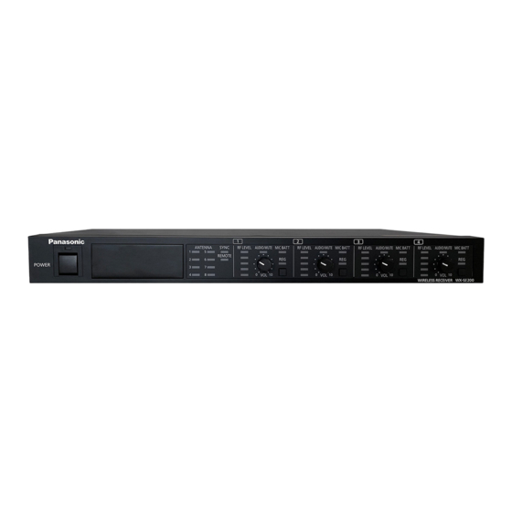
Parts and their names Front A Power switch [POWER] Turns the power ON/OFF. B Power indicator (green) Lights when the power is turned ON. Goes off when the power is turned OFF. C Status indicator [STATUS] Indicates the status of communication with the extension receiver. On (green): Normal Blinking (green): Error (no receiver or unable to communicate with the extension receiver) Off: Power is OFF. - Page 13 F Volume adjustment knob [VOL 0, 10] Adjusts the volume of the microphone on the respective channel. G Microphone battery indicator [MIC BATT] Changes color (green/orange/red) depending on the residual battery level of the microphones on each channel. See “Confirm the remaining battery level of the microphone”...
- Page 14 Parts and their names Rear J Extension receiver connector [RCVR IN] Connect the receiver (EXT OUT) and the extension receiver (RCVR IN) with a LAN cable (page 17). K Channel output connectors [CH OUT -10 dBV 600 Ω 1/2/3/4] Individually outputs the audio from each channel. L External input connector [AUDIO IN -10 dBV 600 Ω] Takes external audio input to be mixed and sent to the mix output connector. M Mix output connector [MIX OUT -10 dBV 600 Ω] Outputs audio obtained by mixing the audio from each channel with the audio input from the [AUDIO IN] connector.
-
Page 15: Installation
Installation ■ Installation precautions Always ask a retailer to perform these operations. Before installation, set the power switch on the devices you want to connect to OFF. Warning Carefully read the “Precautions” section and follow all of its instructions. - Page 16 Installation Do not install the product in the following places Places exposed to direct sunlight or hot air currents Places exposed to large amounts of humidity and/or dust Places with a lot of condensation, subject to extreme temperature variation, or with very high humidity ...
- Page 17 Avoid subjecting the product to shocks Protect the product from strong hits or shocks. These may cause damage to the product. LAN cable LAN cable not included with the antenna. Use a Cat 5 (or Cat 5e or Cat 6) straight network LAN cable. There is a maximum cable length depending on the connection method.
-
Page 18: Installing In A Rack
Installation ■ Installing in a rack The extension receiver can be installed within a rack. Use one of the following racks (sold separately) for installation. EIA-standard product: EIA 19-inch rack, at least 450 mm (17-5/8 inches) long Remove the rubber feet (x4) on the bottom of the extension receiver Rubber feet Use the included rack-bracket screws (x4) to attach the rackmount brackets to both sides of the extension receiver... - Page 19 Install the extension receiver in the rack Use rack-installation screws (x4) to securely fix the extension receiver. Rack-installation torque: 2.0 N•m to 2.4 N•m {20.5 kgf•cm to 24.5 kgf•cm} Rack-installation screws x4 (locally procured) Make sure that the temperature inside the rack does not exceed +45 °C Important (113 °F).
-
Page 20: Connections
Connections ■ Connecting the Euroblock connectors The audio input and output connectors of the extension receiver use removable Euroblock connectors. Connecting wires to the included Euroblock connectors Use a flat-head screwdriver to loosen the screws on the Euroblock connector. Remove a piece of coating from the wire to expose the conductor. -
Page 21: Connecting Audio Output
■ Connecting audio output The extension receiver can output the audio from the microphones on each channel or the collective mixed audio from all channels to an amplifier (or mixer). Connect an external device such as an amplifier to the [CH OUT] or [MIX OUT] connector on the extension receiver. -
Page 22: Connecting With A Receiver
Connections ■ Connecting with a receiver You can add four channels (four microphones) to the number of channels (microphones) that can be used simultaneously by connecting one extension receiver to a receiver. Up to one extension receiver can be connected, and a maximum of eight channels (eight microphones) can be used simultaneously with the WX-SR204P. - Page 23 The extension receiver input connector of this product is a proprietary Important type. Do not connect any PoE devices (hubs or routers equipped with PoE). Doing so may cause malfunctions. Important Be sure to use a straight (non-crossover) LAN cable to connect between the receiver and the extension receiver.
-
Page 24: Pairing
Maximum number of microphones receiver microphones that can be paired that can be used simultaneously WX-SE200P 6 per channel 4 (1 per channel) Refer to the microphone manual for details on the pairing procedure. Saving the pairing information for a paired microphone takes Important approximately 10 seconds. - Page 25 Pair the microphone Keep the [REG] button on a turned ON microphone pressed for at least two seconds to start pairing it (the microphone [PWR] indicator will blink orange). If pairing is completed successfully, the [PWR] indicator on the microphone will switch to the normal status according to the remaining battery level (green, orange, or red), and the [REG] indicator on the paired channel on the extension receiver lights green for one second and goes off.
-
Page 26: Wired Pairing
Pairing ■ Wired pairing Pair a microphone to the receiver via a wired connection. The wired connection uses a conversion cable (micro type B male to type A female; locally procured) and a USB 2.0 cable (type A male to micro type B male; locally procured). * Use a USB host (OTG) cable as conversion cable. - Page 27 Pair the microphone to this product. Make sure that the [POWER] indicator on the extension receiver lights green, then press for at least two seconds the [REG] button of the channel to which you want to pair a microphone. Both the microphone and the extension receiver will enter pairing mode and pairing will start.
-
Page 28: How To Use
How to use ■ Operating microphones Follow the steps below to operate the product. Reception Power indicator Audio level indicator level indicator This product Power switch Volume adjustment knob Turn ON this product and the receiver Turn the [POWER] switch on the receiver with this product connected and the [POWER] switch on this product to ON. -
Page 29: Confirm The Signal Reception Level
■ Confirm the signal reception level You can confirm the signal reception status. Shows the reception level of the microphone signal on each channel in five increments. Reception level indicator This product [RF LEVEL] indicator display Indicator Status On (5 green lines) Level 5 (Max.) On (4 green lines) Level 4... -
Page 30: Confirm The Remaining Battery Level Of The Microphone
How to use ■ Confirm the remaining battery level of the microphone The [MIC BATT] indicator shows the battery level of the microphones on each channel in three increments. (The indicator will stay off if there is no battery information from the microphone) Microphone battery indicator This product... -
Page 31: Confirm The Paired Microphones
■ Confirm the paired microphones Set the extension receiver to pairing confirmation mode Make sure that the [POWER] indicator on the receiver with this product connected and the [POWER] and [STATUS] indicators on this product are lit green, shortly press the [REG] button once on a channel which you choose to check among from the channels communicating with microphones. - Page 32 Important How to use Pairing confirmation is possible for the channels communicating with microphone (the channel on which (the [RF LEVEL] indicator has at least one line lit). Pressing the [REG] button on a channel with no microphones communication will do nothing. ...
-
Page 33: Dimensions
Dimensions Unit: mm (inch) 420 (16-9/16) -
Page 34: Troubleshooting
Troubleshooting Please check the common problems listed in this table before seeking professional help. If none of the tips provided here help, if you are dealing with a problem not listed here, or if you are otherwise uncertain, contact your retailer for more information. Reference Problem Cause/measure... -
Page 35: Specifications
Specifications Power 120 V AC, 60 Hz Power consumption 10 W Frequency response 50 Hz to 15 kHz Channel output: 70 dB or more Mixing output: 64 dB or more Extension No. of 1 (input: 1) receiver input connectors connector Connector RJ-45 Compatible... -
Page 36: Standard Accessories
Specifications Standard accessories Operating Instructions (this manual)..................1 Warranty Card ........................1 Rack mount brackets ......................2 Rack mount bracket screws (M4 x 10 mm) ................4 6-pin Euroblock connectors ....................3... -
Page 37: Précautions De Sécurité
Précautions de sécurité AVERTISSEMENT : ATTENTION Pour éviter les risques d’incendie et ou RISQUE DE CHOC de choc électrique, n’exposez pas ÉLECTRIQUE NE PAS OUVRIR l’appareil à la pluie ou à l’humidité. ATTENTION: AFIN DE PRÉVENIR LE RISQUE DE CHOCS ... - Page 38 Nom commercial : surface de l’appareil. Panasonic Vous devez noter le numéro de modèle et N° de modèle : WX-SE200P le numéro de série de cet appareil dans Partie responsable : l’espace prévu à cet effet et conserver Panasonic Corporation of North America cette notice comme preuve d’achat afin...
- Page 39 IMPORTANTES CONSIGNES DE SÉCURITÉ 1) Lire ces instructions. 2) Conserver ces instructions. 3) Respecter ces instructions. 4) Suivre toutes les instructions. 5) Ne pas utiliser cet appareil près de l’eau. 6) Nettoyer avec un chiffon sec seulement. 7) Éloigner l’appareil de toute source de chaleur telle que radiateurs et autres éléments de chauffage (incluant les amplificateurs).
-
Page 40: Aperçu Du Produit
Précautions de sécurité Aperçu du produit Ce produit est un récepteur d’extension pour les systèmes de microphones numériques sans fil 1,9 GHz. Le connecter à un récepteur sans fil (WX-SR204P : vendu séparément) permet de recevoir l’audio de microphones sans fil (WX-ST200P et WX-ST400P, tous deux vendus séparément) via une antenne sans fil (WX-SA250P : vendue séparément) et le récepteur sans fil et de régler le volume de sortie audio. -
Page 41: Déni De La Garantie
Déni de la garantie EN AUCUN CAS Panasonic Connect Co., Ltd. NE SERA TENU POUR RESPONSABLE POUR TOUTE PARTIE OU TOUTE PERSONNE, À L’EXCEPTION DU REMPLACEMENT OU D’UNE MAINTENANCE RAISONNABLE DE CE PRODUIT POUR LES CAS CITÉS, INCLUS MAIS NON LIMITÉS À CE QUI SUIT : A TOUT DOMMAGE OU PERTE, Y COMPRIS SANS LIMITATION, DIRECT OU INDIRECT, SPÉCIAL, IMPORTANT OU EXEMPLAIRE, SURVENANT OU CONCERNANT LE PRODUIT ;... - Page 42 Table des matières Précautions de sécurité ……………… 37 Aperçu du produit ………………………… 40 Limitation de responsabilité …………… 40 Déni de la garantie ……………………… 41 Droits d’auteur …………………………… 41 Abréviations ……………………………… 41 Précautions ……………………………… 43 Précautions d’utilisation ……………… 45 Nomenclature des pièces …………… 47 Installation ………………………………...
-
Page 43: Précautions
Précautions Confier les opérations de montage à un détaillant Les opérations de montage nécessaires à l’installation de ce produit exigent des compétences et de l’expérience. Il existe un risque d’incendie, de choc électrique, de blessures et de dommages matériels. Demandez toujours à un détaillant de le faire. Serrer les vis et les boulons avec les outils spécifiés Le non-respect de cette consigne pourrait entraîner la chute de pièces provoquant des accidents et des blessures. - Page 44 Précautions Ne pas installer le produit dans un lieu où il existe un risque de dommage par de l’eau de mer ou des gaz corrosifs L’unité de montage risque de se détériorer et d’entraîner des accidents et des blessures. Ne pas installer dans des endroits exposés à une grande quantité d’humidité...
-
Page 45: Précautions D'utilisation
Précautions d’utilisation En dehors de ce qui précède “Précautions”, assurez-vous de suivre les points ci-dessous. Ce produit est destiné à une utilisation à l’intérieur uniquement Il ne peut pas être utilisé en extérieur. Évitez d’exposer le produit à la lumière directe du soleil pendant de longues périodes et ne l’installez pas près d’un climatiseur ou d’un appareil de chauffage. - Page 46 Précautions d’utilisation Quand l’interrupteur d’alimentation est mis sur ON ou OFF Tous les périphériques et amplificateurs de puissance connectés doivent être éteints avant d’actionner l’interrupteur d’alimentation. Le non-respect de cette consigne pourrait engendrer un bruit de cliquetis qui pourrait endommager les haut-parleurs ou d’autres périphériques.
-
Page 47: Nomenclature Des Pièces
Nomenclature des pièces Avant A Interrupteur d’alimentation [POWER] Active/coupe l’alimentation. B Voyant d’alimentation (vert) S’allume quand l’alimentation est activée. S’éteint quand l’alimentation est coupée. C Voyant d’état [STATUS] Indique l’état de la communication avec le récepteur d’extension. Allumé (vert) : Normale Clignotant (vert) : Erreur (pas de récepteur ou communication impossible avec le récepteur d’extension) Éteint : L’alimentation est coupée. - Page 48 Nomenclature des pièces Si le bouton de réglage du volume est actionné lors de la télécommande externe, le voyant de niveau de volume clignote rapidement (rouge) et le réglage du volume n’est pas possible. F Bouton de réglage du volume [VOL 0, 10] Règle le volume du microphone sur le canal respectif.
- Page 49 Arrière J Connecteur de récepteur d’extension [RCVR IN] Connectez le récepteur (EXT OUT) et le récepteur d'extension (RCVR IN) à l'aide d'un câble LAN (page 52). K Connecteurs de sortie de canal [CH OUT -10 dBV 600 Ω 1/2/3/4] Sortie individuelle de l’audio de chaque canal. L Connecteur d’entrée externe [AUDIO IN -10 dBV 600 Ω] Prend l’entrée audio externe à mixer et à envoyer vers le connecteur de sortie de mixage.
-
Page 50: Installation
Installation ■ Précautions d’installation Demandez toujours à un détaillant d’effectuer ces opérations. Avant l’installation, réglez l’interrupteur d’alimentation sur les dispositifs que vous souhaitez connecter sur OFF. Avertissement Lisez attentivement la section “Précautions” et suivez toutes les instructions. Reportez-vous également au manuel des dispositifs que vous connectez. - Page 51 Emplacement d’installation Ce produit génère une grande quantité de chaleur. Quand vous installez le produit près d’un mur ou d’un plafond, assurez-vous qu’il y a au moins 10 cm (3-15/16 pouces) de dégagement sur tous les côtés (voir figure ci-dessous).
- Page 52 Installation Alimentation électrique Mettre l’interrupteur d’alimentation sur OFF éteindra le produit mais n’interrompra pas la circulation du courant. Connectez le cordon d’alimentation au moyen d’un dispositif de coupure de courant de l’une des façons suivantes afin de pouvoir le mettre hors tension facilement.
-
Page 53: Installation Dans Un Rack
■ Installation dans un rack Le récepteur d’extension peut être installé dans un rack. Utilisez l’un des racks suivants (vendus séparément) pour l’installation. Produit conforme à la norme EIA : Rack EIA 19 po, d’au moins 450 mm (17-5/8 po) de long Retirer les pieds en caoutchouc (x4) sur le dessous du récepteur d’extension... - Page 54 Installation Installer le récepteur d’extension dans le rack Utilisez des vis d’installation en rack (x4) pour fixer solidement le récepteur d’extension. Couple d’installation du rack : 2,0 N•m à 2,4 N•m {20,5 kgf•cm à 24,5 kgf•cm} Vis de support d’installation en rack x4 (à...
-
Page 55: Connexions
Connexions ■ Connexion des connecteurs Euroblock Les connecteurs d’entrée et de sortie audio du récepteur utilisent des connecteurs Euroblock amovibles. Connexion des fils aux connecteurs Euroblock fournis Utilisez un tournevis à tête plate pour desserrer les vis du connecteur Euroblock. Enlevez un morceau de revêtement du fil pour exposer le conducteur. -
Page 56: Connexion De La Sortie Audio
Connexions ■ Connexion de la sortie audio Le récepteur d’extension peut émettre l’audio des microphones de chaque canal ou l’audio mixé collectif de tous les canaux vers un amplificateur (ou un mélangeur). Connectez un appareil externe tel qu’un amplificateur au connecteur [CH OUT] ou [MIX OUT] du récepteur d’extension. -
Page 57: Connexion D'un Récepteur
■ Connexion d’un récepteur Vous pouvez ajouter quatre canaux (quatre microphones) au nombre de canaux (microphones) utilisables simultanément en connectant un récepteur d’extension au récepteur. Jusqu’à un récepteur d’extension peut être connecté et huit canaux (huit microphones) au maximum peuvent être utilisés simultanément avec le WX-SR204P. Connecter le récepteur et le récepteur d’extension via un câble LAN (page 52) Connectez le connecteur [EXT OUT] du récepteur d’extension et le connecteur [RCVR... - Page 58 Connexions Le connecteur d’entrée du récepteur d’extension de ce produit est de Important type propriétaire. Ne connectez aucun dispositif PoE (concentrateurs ou routeurs équipés de PoE). Ceci pourrait provoquer des dysfonctionnements. Important Veillez à utiliser un câble LAN droit (non croisé) pour connecter le récepteur et le récepteur d’extension.
-
Page 59: Appairage
Nombre maximal de microphones Nombre maximal de microphones d’extension pouvant être jumelés pouvant être utilisés simultanément WX-SE200P 6 par canal 4 (1 par canal) Reportez-vous au manuel du microphone pour plus de détails sur la procédure d’appairage. L’enregistrement des informations d’appairage pour un microphone jumelé prend Important environ 10 secondes. - Page 60 Appairage Jumeler le microphone Maintenez le bouton [REG] d’un microphone allumé pressé pendant au moins deux secondes pour commencer l’appairage (le voyant [PWR] du microphone clignote en orange). Si l’appairage s’est effectué avec succès, le voyant [PWR] du microphone passe à l’état normal selon le niveau de charge restant (vert, orange ou rouge), le voyant [REG] du canal jumelé...
-
Page 61: Appairage Filaire
■ Appairage filaire Jumelez un microphone au récepteur via une connexion filaire. La connexion filaire utilise un câble de conversion (mâle micro type B à femelle type A ; à se procurer localement) et un câble USB 2.0 (mâle type A à mâle micro type B ; à se procurer localement). - Page 62 Appairage Jumeler le microphone à ce produit. Assurez-vous que le voyant [POWER] du récepteur d’extension s’allume en vert, puis appuyez pendant au moins deux secondes sur le bouton [REG] du canal auquel vous voulez jumeler un microphone. Le microphone et le récepteur d’extension passent en mode appairage et l’appairage commencera.
-
Page 63: Utilisation
Utilisation ■ Utilisation des microphones Suivez les étapes ci-dessous pour actionner le produit. Voyant Voyant du niveau Voyant du niveau audio d’alimentation de réception Ce produit Interrupteur d’alimentation Bouton de réglage du volume Activer ce produit et le récepteur Mettez l’interrupteur [POWER] du récepteur connecté à ce produit et l’interrupteur [POWER] de ce produit sur ON. -
Page 64: Confirmer Le Niveau De Réception De
Utilisation ■ Confirmer le niveau de réception de signal Vous pouvez confirmer l’état de réception de signal. Affiche le niveau de réception du signal du microphone sur chaque canal sous forme de cinq incréments. Voyant du niveau de réception Ce produit Affichage du voyant [RF LEVEL] Voyant État... -
Page 65: Confirmer Le Niveau De Pile Restant Du
■ Confirmer le niveau de pile restant du microphone Le voyant [MIC BATT] indique le niveau de pile des microphones sur chaque canal en trois incréments. (Le voyant restera éteint s’il n’y a pas d’informations de pile provenant du microphone) Voyant de pile du microphone Ce produit Affichage du voyant [MIC BATT]... -
Page 66: Confirmer Les Microphones Jumelés
Utilisation ■ Confirmer les microphones jumelés Régler le récepteur d’extension sur le mode de confirmation de l’appairage Assurez-vous que le voyant [POWER] du récepteur connecté à ce produit et les voyants [POWER] et [STATUS] de ce produit s’allument en vert, et appuyez un court moment sur le bouton [REG] une fois sur un canal que vous choisissez de vérifier parmi les canaux communiquant avec les microphones. - Page 67 Important La confirmation de l’appairage est possible pour les canaux communiquant avec le microphone (le canal sur lequel le voyant [RF LEVEL] a au moins une ligne allumée). Appuyer sur le bouton [REG] d’un canal sans communication microphonique n’aura aucun effet. ...
-
Page 68: Dimensions
Dimensions Unité : mm (po) 420 (16-9/16) -
Page 69: Diagnostic Des Pannes
Diagnostic des pannes Vérifiez les problèmes courants énumérés dans ce tableau avant de demander l’aide d’un professionnel. Si aucun des conseils fournis ici ne sont utiles, si vous rencontrez un problème non répertorié ici, ou en cas de doutes, contactez le détaillant pour plus d’informations. Page de Problème Cause/mesure... -
Page 70: Spécifications
Spécifications Alimentation électrique 120 V CA, 60 Hz Consommation électrique 10 W Réponse en fréquence 50 Hz à 15 kHz Sortie de canal : 70 dB ou plus Sortie de mixage : 64 dB ou plus Connecteur Nombre de 1 (entrée : 1) d’entrée du connecteurs récepteur... -
Page 71: Accessoires Standard
Accessoires standard Instructions d’utilisation (ce manuel) ..................1 Carte de garantie ........................1 Supports de montage en rack ....................2 Vis de supports de montage en rack (M4 x 10 mm) ..............4 Connecteurs Euroblock 6 broches ..................3... - Page 72 Panasonic will not take responsibility for any accident or damage caused by using the product with methods or parts other than those specified in this manual. Damages hence suffered by the product will not be covered by the warranty. Panasonic Corporation of North America Two Riverfront Plaza, Newark, NJ 07102-5490 https://na.panasonic.com/us/...