Table of Contents
Advertisement
Available languages
Available languages
Quick Links
Operating Instructions
Included Installation Instructions
Wireless Receiver
WX-SR204P
Model No.
Before attempting to connect or operate this product, please read these instructions
carefully and save this manual for future use.
The model number is abbreviated in some descriptions in this manual.
PUQX1021YA
Advertisement
Chapters
Table of Contents

Related Manuals for Panasonic WX-SR204P


Summary of Contents for Panasonic WX-SR204P
- Page 1 Operating Instructions Included Installation Instructions Wireless Receiver WX-SR204P Model No. Before attempting to connect or operate this product, please read these instructions carefully and save this manual for future use. The model number is abbreviated in some descriptions in this manual.
-
Page 2: Safety Precautions
ON-OFF switch is in the ON position. Supplier’s Declaration of Unplug the power cord to disconnect the conformity main power for all units. Trade Name: Panasonic Model No.: WX-SR204P Responsible Party: Panasonic Corporation of North America Two Riverfront Plaza, Newark, NJ 07102-5490 Support Contact: 1-800-491-9986 wirelessmicsupport@us.panasonic.com... - Page 3 For U.S.A. For U.S.A. NOTE: This equipment has been tested The model number and serial number of and found to comply with the limits for a this product may be found on the surface Class A digital device, pursuant to part 15 of the unit.
- Page 4 Safety precautions IMPORTANT SAFETY INSTRUCTIONS 1) Read these instructions. 2) Keep these instructions. 3) Heed all warnings. 4) Follow all instructions. 5) Do not use this apparatus near water. 6) Clean only with dry cloth. 7) Do not install near any heat sources such as radiators, heat registers, stoves, or other apparatus (including amplifiers) that produce heat.
-
Page 5: Product Overview
It is supplies power to wireless antennas. Up to 8 wireless antennas can be connected at once. The wireless receiver WX-SR204P can receive audio from up to 4 microphones. Up to 8 microphones can be used by connecting an extension receiver (WX-SE200P: sold separately) to this product. - Page 6 Safety precautions Example of wireless synchronization of multiple systems (when the receiver of room B is set as the main system, and all the others are set as the sub systems) Areas to be wirelessly synchronized Room A Room B Room C (main system) Reference antenna...
-
Page 7: Related Devices
The related products of the1.9 GHz digital wireless microphone system series are as follows: Wireless receiver (sold Wireless receiver (this Extension Receiver (sold separately) product) separately) WX-SR202P WX-SR204P WX-SE200P Wireless microphone Wireless microphone Wireless antenna (handheld) (tie pin type) (sold (sold separately) (sold separately) -
Page 8: Limitation Of Liability
IMPROVEMENTS OF THIS PUBLICATION AND/OR THE CORRESPONDING PRODUCT(S). Disclaimer of Warranty IN NO EVENT SHALL Panasonic Connect Co., Ltd. BE LIABLE TO ANY PARTY OR ANY PERSON, EXCEPT FOR REPLACEMENT OR REASONABLE MAINTENANCE OF THE PRODUCT, FOR THE CASES, INCLUDING BUT NOT LIMITED TO BELOW:... -
Page 9: Open Source Software
Copyright, etc. Excluding the parts mentioned above, the rights to this software and other pieces of intellectual property belong to the Panasonic Connect Co., Ltd. or to third parties, and are not transferred to the customer. Panasonic Connect Co., Ltd. does not take any responsibility for damages, losses, etc. -
Page 10: Network Precautions
Abbreviations This manual uses the following abbreviations. “Wireless Receiver (WX-SR204P)" is referred to as "wireless receiver”, “receiver”, “this product”, or “the product”. “Extension Receiver (WX-SE200P: sold separately)” is referred to as “extension receiver”. -
Page 11: Table Of Contents
Table of contents Safety precautions ……………………… 2 How to use ……………………………… 52 Product overview ………………………… 5 Operation ………………………………… 52 System overview ………………………… 5 Confirm the signal reception level ……… 53 Related devices ………………………… 7 Confirm the remaining battery level of the Limitation of liability ………………………... -
Page 12: Precautions
Precautions Entrust building operations to a retailer The building operations needed to install this product require skill and experience. There is a risk of fires, electric shocks, injuries, and damage to property. Always ask a retailer to do this. Tighten screws and bolts with the specified tools Failing to do so may cause parts to fall leading to accidents and injuries. - Page 13 Do not place on unstable surfaces Failing to do so may cause the product to fall leading to accidents and injuries. Do not use where there is a risk of exceeding the maximum recommended wattage for the socket or the wiring, and only use 120 V current Overloading multi-outlet extension cords could result in overheating and fires.
-
Page 14: Usage Precautions
Usage precautions Other than the aforementioned “Precautions”, make sure to follow the points below. This product is intended for indoor use only It cannot be used outdoors. Avoid exposing the product to direct sunlight for extended periods of time, and do not install it near air conditioners or heaters. - Page 15 Network security Periodically change the password by the support software to improve Important security. System start-up time In order to ensure the privacy of the microphone signals, the system checks the authentication data of all connected antennas and paired microphones (up to 48 microphones) during start- up.
-
Page 16: Parts And Their Names
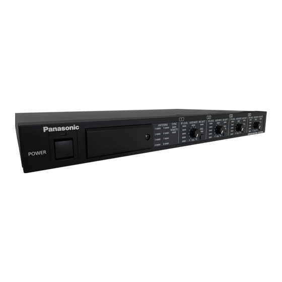
Parts and their names Front * The switch cover is removed in this illustration A Power switch [POWER] Turns the receiver ON/OFF. B Power indication (green) Lights on as the receiver is turned ON. Goes off as the receiver is turned OFF. C Switch cover Loosen the screw and remove the switch cover to gain access to the switches for adjusting the receiver (D), the connector (E), and the indicators (F). - Page 17 G Antenna indicators [ANTENNA 1/2/3/4/5/6/7/8] Important They show the system status during start-up (“Operation” (page 52)) and show the status of connected antennas during operation. On (green): Normal connection On (orange): Connection error with the antenna Checks the connection with the antennas during the start-up of the receiver.
- Page 18 Important Parts and their names Main system: The system (receiver) acting as the reference for the wireless synchronization Sub-system: The systems (receivers) synchronized to the main system when operating with wireless synchronization Stand-alone system: Systems (receivers) which are not synchronized to other systems I External remote indicator [REMOTE] Lights green in the external remote state (when this device is being controlled remotely).
- Page 19 M Microphone remaining battery indicator [MIC BATT] Changes color (green/orange/red) depending on the residual battery level of the microphones on each channel. See “Confirm the remaining battery level of the microphone” (page 54) for details. The external remote state can be forcibly canceled by keeping the [REG] buttons of CH1 and CH2 pressed simultaneously for more than two seconds while the receiver is powered ON.
- Page 20 Use LAN cables to connect the antennas. The antenna connected to [ANTENNA 1] will be used as the reference antenna for wireless synchronization. (page 38) S Channel output connectors [CH OUT -10 dBV 600 Ω 1/2/3/4] Individually outputs the audio from each channel. WX-SR204P: 1/2/3/4 T External input connector [AUDIO IN -10 dBV 600 Ω] Takes external audio input to be mixed and sent to the mix output connector. Mix output connector [MIX OUT -10 dBV 600 Ω] Outputs audio obtained by mixing the audio from each channel with the audio from the [AUDIO IN] connector.
-
Page 21: Installation
Installation ■ Installation precautions Always ask a retailer to perform these operations. Before installation, set the power switch on the devices you want to connect to OFF. Warning Carefully read the “Precautions” section and follow all of its instructions. - Page 22 Installation Do not install the product in the following places Places exposed to direct sunlight or hot air currents Places exposed to large amounts of humidity and/or dust Places with a lot of condensation, subject to extreme temperature variation, or with very high humidity ...
- Page 23 Avoid subjecting the product to shocks Protect the product from strong hits or shocks. These may cause damage to the product. LAN cable LAN cable not included with the antenna. Use a Cat 5 (or Cat 5e or Cat 6) straight network LAN cable. There is a maximum cable length depending on the connection method.
-
Page 24: Installing In A Rack
Installation ■ Installing in a rack The receiver can be installed within a rack. Use one of the following racks (sold separately) for installation. EIA-standard product: EIA 19-inch rack, at least 450 mm (17-5/8 inches) long Remove the rubber feet (x4) on the bottom of the receiver Rubber feet Use the included rack-bracket screws (x4) to attach the rackmount brackets to both sides of the receiver... - Page 25 Install the receiver in the rack Use rack-installation screws (x4) to securely fix the receiver. Rack-installation torque: 2.0 N•m to 2.4 N•m {20.5 kgf•cm to 24.5 kgf•cm} Rack-installation screws x4 (locally procured) Make sure that the temperature inside the rack does not exceed +45 °C Important (113 °F).
-
Page 26: Connections
Connections ■ Connecting with antennas Up to 8 wireless antennas can be connected at once. The antenna connected to the [ANTENNA 1] connector will be used as the reference antenna for wireless synchronization. Always connect a reference antenna when choosing either “main system”... -
Page 27: Connecting The Euroblock Connectors
■ Connecting the Euroblock connectors The audio input and output connectors of the receiver use removable Euroblock connectors. Connecting wires to the included Euroblock connectors Use a flat-head screwdriver to loosen the screws on the Euroblock connector. Remove a piece of coating from the wire to expose the conductor. Twist the conductor and insert it into the Euroblock connector. -
Page 28: Connecting Audio Output
OUT] connector or [MIX OUT] connector of this product. The [CH OUT] connector can output the audio from two channels through a single Euroblock connector, and can output the audio from four channels through two Euroblock connectors in the case of the WX-SR204P. Antenna 8 Antenna 2... -
Page 29: Connecting An Extension Receiver
Up to one extension receiver can be connected, and a maximum of eight channels (eight microphones) can be used simultaneously with the four-channel model WX-SR204P. Connect this product and the extension receiver with a LAN cable (page 23). - Page 30 Connections The extension receiver output connector for this product is a proprietary Important type. Do not connect any PoE devices (hubs or routers equipped with PoE). Doing so may cause malfunctions. Important Be sure to use a straight (non-crossover) LAN cable to connect between this product and the extension receiver.
-
Page 31: Connecting To A Pc For Configuration
■ Connecting to a PC for configuration/maintenance Connect the [100BASE-TX] connector on the receiver to a PC installed the support software via a LAN cable Cat 5 (or Cat 5e or Cat 6) (locally procured). Receiver (Rear) Network connector LAN cable PC installed support software... -
Page 32: Connecting With Microphones
Connections ■ Connecting with microphones Connect the [SET] connector of the microphone to the [SET] connector of the wireless receiver via a USB 2.0 cable (type A male to micro type B male; locally procured) and a conversion cable (micro type B male to type A female; locally procured). This is necessary for the wired pairing of microphones to the receiver. -
Page 33: Installing Antennas
Installing antennas ■ Before you start This section describes some considerations regarding the placement and installation of antennas. Refer to the wireless antenna (WX-SA250P) manual for practical installation instructions. ■ Antenna wireless output level and placement Antenna wireless output level (antenna field selection) ... - Page 34 Installing antennas Antenna field selection Less than 10 m (33 ft) Less than 20 m (66 ft) Less than Less 10 m (33 ft) Approx. than 20 m 15 m Approx. (66 ft) (49 ft) 8 m (26 ft) Coverage area of “Small” Coverage area of “Medium”...
- Page 35 Considerations on antenna placement (multiple antennas connected to the same receiver) The antennas should be placed in such a way as to cover the whole usage area of the microphones, divided by the circles (or other coverage area shapes) which represent the area covered by each antenna.
- Page 36 Installing antennas Wall installation Other than on the ceiling, antennas can also be installed on walls. The surface of the area covered by each antenna is approximately half as big when placed on a wall than when placed on the ceiling. Achieving the same coverage with wall installation as with ceiling installation requires the same amount of antennas to be installed on the opposite wall as well.
- Page 37 Microphone stand installation When installing the antennas on microphone stands, consider the same circular coverage areas as for ceiling installation. Microphone stand installation...
-
Page 38: Multiple System Operation
Installing antennas ■ Multiple system operation Wireless synchronization considerations When multiple systems will be used in the same room, wireless synchronization between the receiving systems is necessary to prevent limitations on the number of microphones that can be used and audio dropouts due to radio wave interference. Reference Reference antenna... - Page 39 When performing wireless synchronization, one system (receiver) must be set as main system which will become the reference for the synchronization of all the other systems that are set as sub-systems. The wireless synchronization is performed when the reference antenna (the antenna connected to the [ANTENNA 1] connector) of the main system is detected by the reference antenna of the sub-systems.
-
Page 40: Settings
Settings ■ Antenna field selection Set the wireless output level of the antennas through the configuration switches No.1 and No.2, or alternatively set it individually by the configuration/maintenance PC. Choose the most suitable wireless output level of the antenna (antenna field selection) according to the usage environment. - Page 41 Important Too strong of a wireless output level may result in wireless interference. Should that happen, lower the wireless output level (antenna field selection) as much as is possible without causing the audio dropouts within the usage area of the microphone. ...
-
Page 42: Wireless Synchronization Settings
Settings ■ Wireless synchronization settings Enabling wireless synchronization allows to reduce interference from other 1.9 GHz digital wireless systems when using multiple systems (receivers) installed on the same floor or otherwise in the vicinity of each other. When enabling wireless synchronization, choose the receiver which will act as main system. - Page 43 Configuration switches numbers Wireless synchronization settings No.3 No.4 Stand-alone system (no wireless synchronization) (factory default) Stand-alone system (no wireless synchronization) Sub-system (use wireless synchronization) Main system Changes in the configuration switches are applied during the start- Important up of the receiver. If you have performed any changes while the receiver was ON, turn the power switch OFF and ON again to restart the product.
- Page 44 Settings Wireless synchronization between systems (receivers) Perform Wireless synchronization after installing and connecting the antennas and receivers. Start with the power switch of all receivers set to OFF, then perform the following steps. A Turn ON the power switch of the receiver set to main system. B Turn ON the power switch of the receivers set to sub-systems.
- Page 45 [SYNC] indicator and [MAIN] indicator on the receiver Synchronization Main Wireless synchronization Synchronization status indicator indicator settings on the system with the main system Main system Sub-system Synchronized Important Blinking Sub-system Not synchronized Stand-alone system When synchronization cannot be established or is lost, the audio may become more likely to dropout.
-
Page 46: Microphone Battery Settings
Settings ■ Microphone battery settings Select the type of battery inside the microphone in use through the configuration switch No.5. Make sure to properly configure the battery type in order to correctly assess the remaining battery level of the microphone (page 54). Receiver * The switch cover is removed in this illustration Configuration switches... -
Page 47: Microphone Audio Settings
■ Microphone audio settings Select the audio mode for the microphone in use through the configuration switch No.6. Unless otherwise required, use “standard” mode. “Standard”: The ideal setting for speech, with adjustments in the high-frequencies of the microphone audio. “High-grade”: A setting which prioritizes audio quality. However, it has a longer audio lag than the “standard”... -
Page 48: Pairing
Maximum number of pairable Maximum number of simultaneously Receiver microphones usable microphones WX-SR204P 6 per channel 4 (1 per channel) Refer to the microphone manual for further details on pairing devices. Saving the pairing information for a paired microphone takes Important approximately 10 seconds. - Page 49 Pair the microphone Keep the [REG] button on a turned ON microphone pressed for at least two seconds to start pairing it (the microphone [PWR] indicator will blink orange). If pairing is completed successfully, the [PWR] indicator on the microphone will switch to the normal status according to the remaining battery level (green, orange, or red), and the [REG] indicator on the paired channel on the receiver lights green for one second and goes off.
-
Page 50: Wired Pairing
Pairing ■ Wired pairing Pair a microphone to the receiver via a wired connection. The wired connection uses a conversion cable (micro type B male to type A female; locally procured) and a USB 2.0 cable (type A male to micro type B male; locally procured). * Use a USB host (OTG) cable as conversion cable. - Page 51 Pair the microphone to the receiver Make sure that the [POWER] indicator on the receiver lights green, then press for at least two seconds the [REG] button of the channel to which you want to pair a microphone. Both the microphone and the receiver will enter pairing mode and pairing will start.
-
Page 52: How To Use
How to use ■ Operation Follow the steps below to operate the product. Reception Power indicator Audio level indicator level indicator Receiver Power switch Volume adjustment knob Antenna indicator Turn ON the receiver Turn the power switch of the receiver to ON. ... -
Page 53: Confirm The Signal Reception Level
■ Confirm the signal reception level You can confirm the signal reception status. Shows the reception level of the microphone signal on each channel in five increments. Reception level indicator Receiver [RF LEVEL] indicator display Indicator Status On (5 green lines) Level 5 (Max.) On (4 green lines) Level 4... -
Page 54: Confirm The Remaining Battery Level Of The Microphone
How to use ■ Confirm the remaining battery level of the microphone The [MIC BATT] indicator shows the battery level of the microphones on each channel in three increments. (The indicator will stay off if there is no battery information from the microphone) Microphone battery indicator Receiver... -
Page 55: Confirm The Paired Microphones
■ Confirm the paired microphones Set the receiver to pairing confirmation mode Make sure that the [POWER] indicator on the receiver lights green, and shortly press the [REG] button once on a channel which you choose to check among from the channels communicating with microphones. - Page 56 Important How to use Pairing confirmation is possible for the channels communicating with microphone (the channel on which (the [RF LEVEL] indicator has at least one line lit). Pressing the [REG] button on a channel with no microphones communication will do nothing. ...
-
Page 57: Support Software
Support software Connect the receiver to the configuration/maintenance PC installed the support software to configure the 1.9 GHz digital wireless microphone system and monitor its status. The functions of the support software are as follows. Refer to the support software manual for further details. - Page 58 Support software Requires Function support software Monitors the use of wireless resources on the selected Slot Monitor ● antenna. Simple Spectrum Monitors the frequency spectrum near 1.9 GHz on the ● Analyzer selected antenna. Monitors the reception signal strength and the history Walk Test ●...
-
Page 59: Dimensions
Dimensions Unit: mm (inch) 420 (16-9/16) -
Page 60: Troubleshooting
Troubleshooting Please check the common problems listed in this table before seeking professional help. If none of the tips provided here help, if you are dealing with a problem not listed here, or if you are otherwise uncertain, contact your retailer for more information. Reference Phenomenon Cause/measure... -
Page 61: Specifications
Specifications Power AC120 V 60 Hz Power consumption 55 W Frequency response 50 Hz to 15 kHz Channel output: 70dB or more Mix output: 64dB or more Wireless Maximum antenna connections connectors Connector RJ-45 Compatible Cat 5, Cat 5e, or Cat 6 straight (non-crossover) LAN cables cable No. -
Page 62: Standard Accessories
Specifications Display Common Power, Antennas 1 to 8, Sync, Main, Remote (indicators) Per-channel RF level (5 steps), Audio level/Mute, Microphone Battery, Register Operating temperature range 0 °C to 45 °C (32 °F to 113 °F) Operating humidity range 0 % to 90 % (no condensation) Dimensions Approx. -
Page 63: Précautions De Sécurité
Précautions de sécurité AVERTISSEMENT : ATTENTION Pour éviter les risques d’incendie et ou RISQUE DE CHOC de choc électrique, n’exposez pas ÉLECTRIQUE NE PAS OUVRIR l’appareil à la pluie ou à l’humidité. ATTENTION: AFIN DE PRÉVENIR LE RISQUE DE CHOCS ... - Page 64 Nom commercial : surface de l’appareil. Panasonic Vous devez noter le numéro de modèle et N° de modèle : WX-SR204P le numéro de série de cet appareil dans Partie responsable : l’espace prévu à cet effet et conserver Panasonic Corporation of North America cette notice comme preuve d’achat afin...
- Page 65 IMPORTANTES CONSIGNES DE SÉCURITÉ 1) Lire ces instructions. 2) Conserver ces instructions. 3) Respecter ces instructions. 4) Suivre toutes les instructions. 5) Ne pas utiliser cet appareil près de l’eau. 6) Nettoyer avec un chiffon sec seulement. 7) Éloigner l’appareil de toute source de chaleur telle que radiateurs et autres éléments de chauffage (incluant les amplificateurs).
-
Page 66: Aperçu Du Produit
Il fournit l’alimentation électrique aux antennes sans fil. Jusqu’à 8 antennes sans fil peuvent être connectées simultanément. Le récepteur sans fil WX-SR204P peut recevoir l’audio de 4 microphones maximum. Jusqu’à 8 microphones peuvent être utilisés en connectant un récepteur d’extension (WX-SE200P : vendu séparément) à... - Page 67 Exemple de synchronisation sans fil de systèmes multiples (lorsque le récepteur de la salle B est configuré comme système principal et que tous les autres sont configurés comme sous-systèmes) Zones à synchroniser sans fil Salle A Salle B Salle C (système principal) Antenne de référence Antenne de référence...
-
Page 68: Appareils Associés
1,9 GHz sont les suivants : Récepteur sans fil (vendu Récepteur sans fil (ce Récepteur d'extension séparément) produit) (vendu séparément) WX-SR202P WX-SR204P WX-SE200P Microphone sans fil Microphone sans fil Antenne sans fil (portable) (type pince à cravate) (vendu séparément) (vendu séparément) -
Page 69: Limitation De Responsabilité
PUBLICATION ET/OU LE(S) PRODUIT(S) CORRESPONDANT(S). Déni de la garantie EN AUCUN CAS Panasonic Connect Co., Ltd. NE SERA TENU POUR RESPONSABLE POUR TOUTE PARTIE OU TOUTE PERSONNE, À L’EXCEPTION DU REMPLACEMENT OU D’UNE MAINTENANCE RAISONNABLE DE CE PRODUIT POUR LES CAS CITÉS, INCLUS MAIS NON LIMITÉS À... -
Page 70: Logiciels Libres
Copyright, etc. À l’exception des parties mentionnées ci-dessus, les droits sur ce logiciel et autres éléments de propriété intellectuelle appartiennent à Panasonic Connect Co., Ltd. ou à des tiers, et ne sont pas transférés au client. Panasonic Connect Co., Ltd. n’assume aucune responsabilité pour les dommages, pertes,... -
Page 71: Précautions Relatives Au Réseau
Abréviations Ce manuel utilise les abréviations suivantes. “Ce produit”, “le produit”, “récepteur” ou “récepteur sans fil” désigne le “récepteur sans fil (WX-SR204P)”. “Récepteur d’extension” désigne le “récepteur d’extension (WX-SE200P : vendu séparément)”. “Microphone” désigne le “microphone sans fil (WX-ST200P ou WX-ST400P, tous deux vendus séparément)”. - Page 72 Table des matières Précautions de sécurité ……………… 63 Utilisation ……………………………… 113 Aperçu du produit ………………………… 66 Opération ……………………………… 113 Aperçu du système ……………………… 66 Confirmer le niveau de réception de Appareils associés ……………………… 68 signal ………………………………… 114 Limitation de responsabilité …………… 69 Confirmer le niveau de pile restant du Déni de la garantie ………………………...
-
Page 73: Précautions
Précautions Confier les opérations de montage à un détaillant Les opérations de montage nécessaires à l’installation de ce produit exigent des compétences et de l’expérience. Il existe un risque d’incendie, de choc électrique, de blessures et de dommages matériels. Demandez toujours à un détaillant de le faire. Serrer les vis et les boulons avec les outils spécifiés Le non-respect de cette consigne pourrait entraîner la chute de pièces provoquant des accidents et des blessures. - Page 74 Précautions Ne pas installer le produit dans un lieu où il existe un risque de dommage par de l’eau de mer ou des gaz corrosifs L’unité de montage risque de se détériorer et d’entraîner des accidents et des blessures. Ne pas installer dans des endroits exposés à une grande quantité d’humidité...
-
Page 75: Précautions D'utilisation
Précautions d’utilisation En dehors de ce qui précède “Précautions”, assurez-vous de suivre les points ci-dessous. Ce produit est destiné à une utilisation à l’intérieur uniquement Il ne peut pas être utilisé en extérieur. Évitez d’exposer le produit à la lumière directe du soleil pendant de longues périodes et ne l’installez pas près d’un climatiseur ou d’un appareil de chauffage. - Page 76 Précautions d’utilisation Sécurité du réseau Modifiez périodiquement le mot de passe via le logiciel de soutien pour Important améliorer la sécurité. Temps de démarrage du système Afin d’assurer la confidentialité des signaux microphoniques, le système vérifie les données d’authentification de toutes les antennes connectées et de tous les microphones jumelés (jusqu’à...
-
Page 77: Nomenclature Des Pièces
Nomenclature des pièces Avant * Le cache-interrupteur n’apparaît pas sur cette illustration A Interrupteur d’alimentation [POWER] Allumer/Éteindre le récepteur. B Indication d’alimentation (vert) S’allume quand le récepteur est mis sous tension. S’éteint quand le récepteur est mis hors tension. C Cache-interrupteur Desserrez la vis et retirez le cache-interrupteur pour accéder aux interrupteurs permettant de régler le récepteur (D), le connecteur (E) et les voyants (F). - Page 78 Nomenclature des pièces F Voyant de système principal [MAIN] (vert) (derrière le cache-interrupteur) S’allume lorsque l’interrupteur de configuration de la synchronisation sans fil est réglé sur “système principal”. G Voyants d’antenne [ANTENNA 1/2/3/4/5/6/7/8] Important Ils indiquent l’état du système au démarrage (“Opération” (page 113)) et indiquent l’état des antennes connectées pendant le fonctionnement.
- Page 79 Important Système principal : Système (récepteur) servant de référence pour la synchronisation sans fil Sous-système : Systèmes (récepteurs) synchronisés au système principal lors du fonctionnement avec la synchronisation sans fil Système autonome : Systèmes (récepteurs) qui ne sont pas synchronisés avec d’autres systèmes I Voyant de télécommande externe [REMOTE] S’allume en vert à...
- Page 80 Nomenclature des pièces L Bouton de réglage du volume [VOL 0, 10] Règle le volume des microphones sur chaque canal. M Voyant d’autonomie restante du microphone [MIC BATT] Change de couleur (vert/orange/rouge) en fonction du niveau de pile résiduel des microphones sur chaque canal.
- Page 81 [ANTENNA 1] sera utilisée comme antenne de référence pour la synchronisation sans fil. (page 99) S Connecteurs de sortie de canal [CH OUT -10 dBV 600 Ω 1/2/3/4] Sortie individuelle de l’audio de chaque canal. WX-SR204P : 1/2/3/4 T Connecteur d’entrée externe [AUDIO IN -10 dBV 600 Ω] Prend l’entrée audio externe à mixer et à envoyer vers le connecteur de sortie de mixage.
-
Page 82: Installation
Installation ■ Précautions d’installation Demandez toujours à un détaillant d’effectuer ces opérations. Avant l’installation, réglez l’interrupteur d’alimentation sur les dispositifs que vous souhaitez connecter sur OFF. Avertissement Lisez attentivement la section “Précautions” et suivez toutes les instructions. Reportez-vous également au manuel des dispositifs que vous connectez. - Page 83 Emplacement d’installation Ce produit génère une grande quantité de chaleur. Quand vous installez le produit près d’un mur ou d’un plafond, assurez-vous qu’il y a au moins 10 cm (3-15/16 pouces) de dégagement sur tous les côtés (voir figure ci-dessous). À...
- Page 84 Installation Alimentation électrique Mettre l’interrupteur d’alimentation sur OFF éteindra le produit mais n’interrompra pas la circulation du courant. Connectez le cordon d’alimentation au moyen d’un dispositif de coupure de courant de l’une des façons suivantes afin de pouvoir le mettre hors tension facilement.
-
Page 85: Installation Dans Un Rack
■ Installation dans un rack Le récepteur peut être installé dans un rack. Utilisez l’un des racks suivants (vendus séparément) pour l’installation. Produit conforme à la norme EIA : Rack EIA 19 pouces, d’au moins 450 mm (17-5/8 pouces) de long Retirer les pieds en caoutchouc (x4) sur le dessous du récepteur Pieds en caoutchouc Utiliser les vis de fixation (x4) fournies pour fixer les supports de... - Page 86 Installation Installer le récepteur dans le rack Utilisez des vis d’installation en rack (x4) pour fixer solidement le récepteur. Couple d’installation du rack : 2,0 N•m à 2,4 N•m (20,5 kgf•cm à 24,5 kgf•cm) Vis de support d’installation en rack x4 (à...
-
Page 87: Connexions
Connexions ■ Connexion avec les antennes Jusqu’à 8 antennes sans fil peuvent être connectées simultanément. L’antenne connectée au connecteur à [ANTENNA 1] sera utilisée comme antenne de référence pour la synchronisation sans fil. Connectez toujours une antenne de référence lorsque vous choisissez “système principal” ou “sous-système” comme réglage de synchronisation sans fil (page 103). -
Page 88: Euroblock
Connexions ■ Connexion des connecteurs Euroblock Les connecteurs d’entrée et de sortie audio du récepteur utilisent des connecteurs Euroblock amovibles. Connexion des fils aux connecteurs Euroblock fournis Utilisez un tournevis à tête plate pour desserrer les vis du connecteur Euroblock. Enlevez un morceau de revêtement du fil pour exposer le conducteur. -
Page 89: Connexion De La Sortie Audio
[CH OUT] ou [MIX OUT] de ce produit. Le connecteur [CH OUT] peut émettre l’audio de deux canaux via un seul connecteur Euroblock et peut émettre l’audio de quatre canaux via deux connecteurs Euroblock avec le WX-SR204P. Antenne 8... -
Page 90: Connexion À Un Récepteur D'extension
(microphones) utilisables simultanément en connectant un récepteur d’extension à ce produit. Jusqu’à un récepteur d’extension peut être connecté et huit canaux (huit microphones) au maximum peuvent être utilisés simultanément avec le modèle à quatre canaux WX-SR204P. Connectez ce produit et le récepteur d’extension via un câble LAN (page 84). - Page 91 Le connecteur de sortie du récepteur d’extension pour ce produit est de Important type propriétaire. Ne connectez aucun dispositif PoE (concentrateurs ou routeurs équipés de PoE). Ceci pourrait provoquer des dysfonctionnements. Important Veillez à utiliser un câble LAN droit (non croisé) pour connecter ce produit et le récepteur d’extension.
-
Page 92: Connexion À Un Pc Pour La Configuration
Connexions ■ Connexion à un PC pour la configuration/maintenance Connectez le connecteur [100BASE-TX] du récepteur à un PC équipé du logiciel de soutien via un câble LAN Cat 5 (ou Cat 5e ou Cat 6) (à se procurer localement). Récepteur (arrière) Connecteur réseau Câble LAN Logiciel de soutien... -
Page 93: Connexion Avec Des Microphones
■ Connexion avec des microphones Connectez le connecteur [SET] du microphone au connecteur [SET] du récepteur sans fil via un câble USB 2.0 (mâle type A à mâle micro type B ; à se procurer localement) et un câble de conversion (mâle micro type B à femelle type A ; à se procurer localement). Ceci est nécessaire pour le jumelage câblé... -
Page 94: Installation Des Antennes
Installation des antennes ■ Avant de commencer Cette section décrit quelques considérations concernant l’emplacement et l’installation des antennes. Reportez-vous au manuel de l’antenne sans fil (WX-SA250P) pour des instructions sur l’installation pratique. ■ Niveau et emplacement de la sortie sans fil de l’antenne Niveau de sortie sans fil de l’antenne (sélection du champ d’antenne) ... - Page 95 Sélection du champ d’antenne Moins de 10 m (33 pi) Moins de 20 m (66 pi) Moins de 10 m (33 pi) Environ Moins de 20 m 15 m Environ (66 pi) (49 pi) 8 m (26 pi) Zone de couverture pour “Petit” Zone de couverture pour “Moyen”...
- Page 96 Installation des antennes Considérations sur l’emplacement de l’antenne (plusieurs antennes connectées au même récepteur) Les antennes doivent être placées de manière à couvrir toute la zone d’utilisation des microphones, divisée par les cercles (ou autres formes de zone de couverture) qui représentent la zone couverte par chaque antenne.
- Page 97 Installation murale En dehors du plafond, les antennes peuvent également être installées sur les murs. La surface de la zone couverte par chaque antenne est environ deux fois moins grande lorsqu’elle est placée sur un mur que lorsqu’elle est placée au plafond. Pour obtenir la même couverture avec une installation murale qu’avec une installation au plafond, il faut installer la même quantité...
- Page 98 Installation des antennes Installation du pied de microphone Lors de l’installation des antennes sur un pied de microphone, considérez les mêmes zones de couverture circulaires que pour l’installation au plafond. Installation du pied de microphone...
-
Page 99: Opération De Systèmes Multiples
■ Opération de systèmes multiples Considérations sur la synchronisation sans fil Lorsque des systèmes multiples sont utilisés dans la même salle, la synchronisation sans fil entre les systèmes de réception est nécessaire afin d’éviter de limiter le nombre de microphones utilisables et les pertes audio en raison de l’interférence des ondes radio. - Page 100 Installation des antennes Lors de la synchronisation sans fil, un système (récepteur) doit être défini comme système principal qui deviendra la référence pour la synchronisation de tous les autres systèmes qui sont définis comme sous-systèmes. La synchronisation sans fil est effectuée quand l’antenne de référence (l’antenne connectée au connecteur [ANTENNA 1]) du système principal est détectée par l’antenne de référence des sous-systèmes.
-
Page 101: Réglages
Réglages ■ Sélection du champ d’antenne Réglez le niveau de sortie sans fil des antennes à l’aide des interrupteurs de configuration Nº1 et Nº2, ou bien réglez-le individuellement par le PC de configuration/maintenance. Choisissez le niveau de sortie sans fil le plus approprié de l’antenne (sélection du champ d’antenne) en fonction de l’environnement d’utilisation. - Page 102 Important Réglages Un niveau de sortie sans fil trop élevé peut entraîner des interférences sans fil. Si cela se produit, baissez autant que possible le niveau de sortie sans fil (sélection du champ d’antenne) sans provoquer de pertes audio dans la zone d’utilisation du microphone.
-
Page 103: Réglages De Synchronisation Sans Fil
■ Réglages de synchronisation sans fil L’activation de la synchronisation sans fil permet de réduire les interférences provenant d’autres systèmes numériques sans fil de 1,9 GHz quand des systèmes multiples (récepteurs) sont installés sur le même étage ou à proximité les uns des autres. Quand la synchronisation sans fil est activée, choisir le récepteur qui servira de système principal. - Page 104 Réglages Numéros des interrupteurs de configuration Réglages de synchronisation sans fil No.3 No.4 Système autonome (pas de synchronisation sans fil) (réglage d’usine par défaut) Système autonome (pas de synchronisation sans fil) Sous-système (utilise la synchronisation sans fil) Système principal Les modifications dans les interrupteurs de configuration Important s’appliquent lors du démarrage du récepteur.
- Page 105 Synchronisation sans fil entre systèmes (récepteurs) Effectuez la synchronisation sans fil après avoir installé et connecté les antennes et les récepteurs. Commencez par mettre l’interrupteur d’alimentation de tous les récepteurs sur OFF, puis effectuez les étapes suivantes. A Mettez l’interrupteur d’alimentation du poste récepteur sur ON pour allumer le système principal.
- Page 106 Réglages Voyant [SYNC] et voyant [MAIN] sur le récepteur Réglages de Voyant de Indicateur État de synchronisation synchronisation sans fil synchronisation principal avec le système principal sur le système Allumé Allumé Système principal Important Allumé Éteint Sous-système Synchronisé Clignotant Éteint Sous-système Non synchronisé...
-
Page 107: Réglage De La Batterie Du Microphone
■ Réglage de la batterie du microphone Définissez le type de batterie du microphone utilisé par cet appareil à l’aide du commutateur de réglage des opérations n ° 5. Assurez-vous de configurer correctement le type de pile afin d’évaluer correctement le niveau de pile restant du microphone (page 115). -
Page 108: Réglages Audio Du Microphone
Réglages ■ Réglages audio du microphone Sélectionnez le mode audio pour le microphone utilisé à l’aide de l’interrupteur de configuration N°6. Sauf indication contraire, utilisez le mode “standard”. “Standard” : Le réglage idéal pour la parole, avec des réglages dans les hautes fréquences de l’audio du microphone. -
Page 109: Appairage
Nombre maximal de microphones Récepteur pouvant être jumelés pouvant être utilisés simultanément WX-SR204P 6 par canal 4 (1 par canal) Reportez-vous au manuel du microphone pour plus de détails sur les dispositifs d’appairage. L’enregistrement des informations d’appairage pour un microphone Important jumelé... - Page 110 Appairage Jumeler le microphone Maintenez le bouton [REG] d’un microphone allumé pressé pendant au moins deux secondes pour commencer l’appairage (le voyant [PWR] du microphone clignote en orange). Si l’appairage s’est effectué avec succès, le voyant [PWR] du microphone passe à l’état normal selon le niveau de charge restant (vert, orange ou rouge), le voyant [REG] du canal jumelé...
-
Page 111: Appairage Filaire
■ Appairage filaire Jumelez un microphone au récepteur via une connexion filaire. La connexion filaire utilise un câble de conversion (mâle micro type B à femelle type A ; à se procurer localement) et un câble USB 2.0 (mâle type A à mâle micro type B ; à se procurer localement). - Page 112 Appairage Jumeler le microphone au récepteur Assurez-vous que le voyant [POWER] du récepteur s’allume en vert, puis appuyez pendant au moins deux secondes sur le bouton [REG] du canal auquel vous voulez jumeler un microphone. Le microphone et le récepteur passent en mode appairage et l’appairage commencera.
-
Page 113: Utilisation
Utilisation ■ Opération Suivez les étapes ci-dessous pour actionner le produit. Voyant Voyant du niveau Voyant du niveau audio d’alimentation de réception Récepteur Interrupteur Bouton de réglage du volume Voyant d’antenne d’alimentation Allumer le récepteur Mettez l’interrupteur d’alimentation du récepteur sur ON pour l’allumer. ... -
Page 114: Confirmer Le Niveau De Réception De
Utilisation ■ Confirmer le niveau de réception de signal Vous pouvez confirmer l’état de réception de signal. Affiche le niveau de réception du signal du microphone sur chaque canal sous forme de cinq incréments. Voyant du niveau de réception Récepteur Affichage du voyant [RF LEVEL] Voyant État... -
Page 115: Confirmer Le Niveau De Pile Restant Du
■ Confirmer le niveau de pile restant du microphone Le voyant [MIC BATT] indique le niveau de pile des microphones sur chaque canal en trois incréments. (Le voyant restera éteint s’il n’y a pas d’informations de pile provenant du microphone) Voyant de pile du microphone Récepteur Affichage du voyant [MIC BATT]... -
Page 116: Confirmer Les Microphones Jumelés
Utilisation ■ Confirmer les microphones jumelés Régler le récepteur sur le mode de confirmation de l’appairage Assurez-vous que le voyant [POWER] du récepteur s’allume en vert et appuyez un court moment sur le bouton [REG] une fois sur un canal que vous choisissez de vérifier parmi les canaux communiquant avec les microphones. - Page 117 Important La confirmation de l’appairage est possible pour les canaux communiquant avec le microphone (le canal sur lequel le voyant [RF LEVEL] a au moins une ligne allumée). Appuyer sur le bouton [REG] d’un canal sans communication microphonique ne fera rien. ...
-
Page 118: Logiciel De Soutien
Logiciel de soutien Connectez le récepteur au PC de configuration/maintenance installé le logiciel de soutien pour configurer le système de microphones numériques sans fil de 1,9 GHz et surveiller son état. Les fonctions du logiciel de soutien sont les suivantes. Reportez-vous au manuel du logiciel de soutien pour plus de détails. - Page 119 Logiciel de Fonction soutien requis Moniteur de Surveille l’utilisation des ressources sans fil sur ● fente l’antenne sélectionnée. Analyseur de Surveille le spectre de fréquences proche de 1,9 GHz ● spectre simple sur l’antenne sélectionnée. Surveille l’intensité du signal de réception et Test de marche l’historique des antennes connectées sur le ●...
-
Page 120: Dimensions
Dimensions Unité : mm (pouce) 420 (16-9/16) -
Page 121: Diagnostic Des Pannes
Diagnostic des pannes Vérifiez les problèmes courants énumérés dans ce tableau avant de demander l’aide d’un professionnel. Si aucun des conseils fournis ici ne sont utiles, si vous rencontrez un problème non répertorié ici, ou en cas de doutes, contactez le détaillant pour plus d’informations. Page de Phénomène Cause/mesure... -
Page 122: Spécifications
Spécifications Alimentation électrique CA 120 V 60 Hz Consommation électrique 55 W Réponse en fréquence 50 Hz à 15 kHz Sortie de canal : 70 dB ou plus Sortie mix. : 64 dB ou plus Connecteurs Connexions d’antenne sans maximales Connecteur RJ-45 Câbles... -
Page 123: Accessoires Standard
Affichage Commun Alimentation, antennes 1 à 8, sync, principal, (voyants) télécommande Par canal Niveau de RF (5 niveaux), niveau audio/sourdine, pile de microphone, enregistrement Plage de température de 0 °C à 45 °C (32 °F à 113 °F) fonctionnement Plage d’humidité de 0 % à... - Page 124 Panasonic will not take responsibility for any accident or damage caused by using the product with methods or parts other than those specified in this manual. Damages hence suffered by the product will not be covered by the warranty. Panasonic Corporation of North America Two Riverfront Plaza, Newark, NJ 07102-5490 https://na.panasonic.com/us/...