
Related Manuals for Honeywell HP ProLiant DL360P Gen8


Summary of Contents for Honeywell HP ProLiant DL360P Gen8
- Page 1 HP ProLiant DL360P Gen8 Server Planning Installation Service Guide HWDOC-X330-G August 2020...
- Page 2 Honeywell International Sàrl. While this information is presented in good faith and believed to be accurate, Honeywell disclaims the implied warranties of merchantability and fitness for a purpose and makes no express warranties except as may be stated in its written agreement with and for its customer.
-
Page 3: Table Of Contents
2.1.2 BIOS configuration 2.2 Description 2.2.1 Honeywell server model number 2.2.2 Equipment configuration 2.2.3 Electronics module 2.2.4 Standard features of HP ProLiant DL360p Gen8 server 2.3 Platform information 2.4 Slots configuration 2.4.1 Slot configuration for Experion node setup 2.4.2 Slots configuration 2.4.3 General Ethernet configuration... - Page 4 3.4.3 Connecting the cables 3.4.4 Install air duct baffles and blank panel front covers in cabinet 3.5 Starting the server 3.5.2 Configuring RAID in HP ProLiant DL360p Gen8 server 3.5.3 Starting the TDC emulator services 3.5.4 Checking the LCNP4e/LCNp4e2 status Chapter 4 - Operation 4.1 Server overview...
- Page 5 5.5.5 BIOS settings for 51155539-100 5.5.6 BIOS settings for 51155539-200 5.6 Spare parts - 5 -...
-
Page 6: Chapter 1 - About This Document
Honeywell factory or has manuals dedicated to its installation and service. This server is not a standard HP model and you cannot order it independently from HP. - Page 7 Chapter 1 - About this Document Publication Content Type Experion LCN Hardware UEA installation Upgrade Kit Instructions (51195195-415) Experion LCN Quick Start General hardware/software/migration information Guide (EPDOC-X480-en- 510A) Experion Software Installation Experion software installation (various methods) User's Guide (EPDOC-X136- en-510A) Experion LCN Overview and Bridge hardware installation, software configuration, Implementation Guide...
- Page 8 Chapter 1 - About this Document Publication Content Type Integrated Experion-TPS Supplementary installation and configuration tasks for User's Guide (EPDOC-XX66- Experion TPS Nodes en-510A) Experion PKS R510.1 Planning information for migration of Experion system Migration Planning Guide from legacy R4xx system software to Experion R510.1 software.
-
Page 9: Chapter 2 - Planning
Change Notice (SCN). This server is not a standard HP model and cannot be ordered independently from HP. The Technical Assistance Center (TAC) is trained to support Honeywell platforms. Use of any other server, including a similar HP model, is considered a project special and its TAC support is limited according to the services policy. -
Page 10: Software Requirements
Release Software Change Notice for software applications that have been qualified for use on the HP ProLiant DL360p Gen8 server platform. 2.1.2 BIOS configuration All HP ProLiant DL360p Gen8 server platforms must have the BIOS version P71 02/11/2014 or later.. Description Honeywell server model number Equipment configuration... -
Page 11: Equipment Configuration
(QTY4)/P420i SAS Controller (512MB Cache) (RAID 5 configuration). 2.2.2 Equipment configuration The Honeywell-based HP ProLiant DL360p Gen8 server can be installed in Honeywell 1000 mm deep LCN cabinet only. 2.2.3 Electronics module The tables in this section provide the electronics module for the Honeywell-based HP ProLiant DL360p Gen8 server. -
Page 12: Standard Features Of Hp Proliant Dl360P Gen8 Server
Standard features of HP ProLiant DL360p Gen8 server The common features of HP ProLiant DL360p Gen8 server are as follows: Intel Xeon E5-2620 V2 Ivy Bridge 2.1 GHz or E5 2630V2 2.6 GHz 4 x 256KB L2 Cache 15MB L3... -
Page 13: Platform Information
Consists of one x4 low profile and one x16 half length full height expansion slot Platform information 2.3.1 Honeywell documentation The following table lists other Honeywell publications that may be useful when installing or operating the server platform. Publication Contains information on FE05: Fault Tolerant Ethernet Installation and Service Installing and using FTE. -
Page 14: Slots Configuration
A Local Control Network Processor (LCNP) board and LCN Media Access Unit (MAU) are no longer used if the Server has been upgraded to be an ELCN node. HP ProLiant DL360p Gen8 server has one riser. The details of the slot are as follows: Expansion slot... -
Page 15: General Ethernet Configuration
Low Profile Slot PCIe3 Full height half length slot X 16 X 16 The following is a list of options that can be configured in your platform. Model number Honeywell part number Description TP-LCNP04 51405098-100 LCN Interface card PCIe TP-LCNP05 51454493-126... -
Page 16: Memory Configuration
The label on the outside of the shipping container identifies the capacity of the memory installed. Honeywell uses the Memory Expansion Model number to help the supplier identify the memory that must be added with the platform. -
Page 17: Standard Memory Configuration
Chapter 2 - Planning CPU1 Channels Slot numbers Population order Channel 4 D; empty H; empty L; empty 2.5.2 Standard memory configuration Tab 100 — The following table provides the memory configuration for Intel Xeon E5-2620 V2 Ivy Bridge 2.1GHz processor with 8GB, consisting of two 4 GB ECC RDIMM (2x4) GB (1600MHz) or faster. CPU1 Channels Slot numbers... -
Page 18: System Specifications
Chapter 2 - Planning CPU1 Channels Slot numbers Population order Channel 1 8GB DDR3 ECC RDIMM Channel 2 8GB DDR3 ECC RDIMM NOTE If customer has 51155539-100 with base memory as 4GB.Then order 2 Nos of MZ-PCEM28 to make it 16GB, Mounting will be as follows CPU1 Channels Slot numbers... - Page 19 Chapter 2 - Planning 2.6.3 Memory Architecture 4 GB (1x4 GB) DDR3-12800 or 8 GB (1x 8 GB) or faster DIMM sockets 24 RDIMM socket DIMM 4 GB or 8 GB DDR3 ECC RDIMM capacities Minimum RAM Tab 100 4 GB (1x4 GB) / Tab 200 8 GB (1x 8 GB) DDR3 ECC RDIMM for faster Maximum Tab 200 8 GB (2x4 GB) / Tab 200 16 GB (2x 8 GB) DDR3 ECC...
- Page 20 Chapter 2 - Planning 2.6.9 Environmental Operating +10° to +35° C (50° to 95° F) with a maximum temperature gradation of temperature 10° per hour. Note : for Altitudes above 2950 feet , the maximum operating temperature is derated 1°F/550ft. The displayed temperature ratings are for sea level.
- Page 21 Chapter 2 - Planning 2.6.12 Altitude Operating 3048 m (10,000 ft). This value may be limited by the type and number of options installed. Maximum allowable altitude change rate is 457 m/min (1500 ft/min). That is 1°F /167.64 meters or 17.22°c/167.64 meters Storage 9144 m (30,000 ft).
-
Page 22: Hard Disk Drive Specifications
2.6.18 Removable media specifications The HP ProLiant DL360p Gen8 server has one SATA DVD- RW drive. The SATA DVD-RW drive is connected to the SATA connector on the motherboard. DC 5 volt power, 6.5 Watts is the operating power requirement for DVD RW drive. -
Page 23: Video Cable
2.6.21 Video cable A correct system startup and operation of the HP ProLiant DL360p Gen8 server requires an industry standard VESA DDC interface with the monitor. If a monitor or video cable that does not support DDC is attached to the Server Platform, the display generator will default to a resolution, which precludes communication with the system software and stops startup. -
Page 24: Safety Compliance
The compliance specifications in this section apply to installations other than cabinets. ATTENTION Honeywell does not claim Safety Compliance or Electromagnetic Compatibility (EMC) Compliance for system equipment configurations that have not been described in this guide as standard system configurations. Any equipment configuration other than that described in this publication decertifies the Safety and EMC compliance of this product. -
Page 25: Safety Compliance
Chapter 2 - Planning Regulatory) for European community. Element Description Emissions IEC 61326, 1997 (Basic Requirements, CISPR 11, Class A) Immunity IEC 61326, 1997 (Basic Requirements) ATTENTION The following formula is a proximity guideline, for use of Portable Transceivers (walkie-talkies) in the frequency range of 80MHz to 1GHz. -
Page 26: Chapter 3 - Installation
CHAPTER NSTALLATION This section describes the procedures for installing the platform and cabling the server in a 1-meter deep Honeywell cabinet. Tasks for installing the server Power and grounding requirements Cabinet spacing requirements Installing the server and connecting the cables... -
Page 27: Cabinet Spacing Requirements
Uninterruptible Power Source (UPS). Cabinet spacing requirements Due to thermal constraints, only one HP ProLiant DL360p Gen8 server can be mounted on a new build 1-meter deep Honeywell MP-C1MCB1 cabinet. The server must be mounted on rack space interval 11U through 15U counting from the bottom of the cabinet and moving up. -
Page 28: Installing The Server And Connecting The Cables
Honeywell model number MP-C1MCB1, was shipped from the Honeywell factory with pre-assembled “Sliding Ready Rails”. The Sliding Ready Rails II kit and 1U Cable Management Arm kit are included with the purchase of Honeywell part number 51155539-100 (Model No. MZ-PCSV82). -
Page 29: Connecting The Cables
1. From the front of the cabinet, open the door to access the mounting rails. 2. Fully extend the right and left Sliding Ready Rails (pre-installed in the Honeywell factory). 3. Lower the server into the J-shaped slots on each slide, starting with the slot that is closest to the cabinet. -
Page 30: Install Air Duct Baffles And Blank Panel Front Covers In Cabinet
Chapter 3 - Installation 5. If necessary, refer to the section Install air duct baffles and blank panel front covers in cabinet. ATTENTION Any unused rack mount space must have an air duct baffle and blank front panel installed. 6. To complete the installation, turn on the server. 3.4.4 Install air duct baffles and blank panel front covers in cabinet Air duct baffles and blank panel front covers ensure that the airflow within the cabinet allows proper... - Page 31 Chapter 3 - Installation 2. Place the blank front panel across the front of the cabinet rails. Attach it to the air duct baffle and right cabinet rail using two machine screws and two external tooth washers threaded into the two clip nuts, and then tighten the screws.
-
Page 32: Starting The Server
Starting the server 3.5.1 To start the server 1. Press the Power On/Standby button on the front panel of HP ProLiant DL360p Gen8 server. 2. Wait for the power light to become solid blue. Configuring RAID in HP ProLiant DL360p Gen8 server... -
Page 33: Checking The Lcnp4E/Lcnp4E2 Status
LCNP4e/LCNp4e2 passed self test. To check the LCNP4e/LCNp4e2 status 1. Choose Start > Programs > Honeywell TPS > LCNP Status. 2. Verify that the LCNP status indicates Passed Self Test and the circle is green. -
Page 34: Chapter 4 - Operation
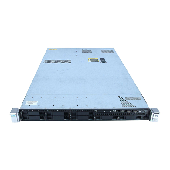
Configuring ControlNet interface card Server overview Front view Rear view 4.1.1 Front view The following image illustrates the front view of the HP ProLiant DL360p Gen8 server. Following is the description for the items in the image. - 34 -... -
Page 35: Rear View
Serial number tab Power On/Standby button and system power LED 4.1.2 Rear view The following image illustrates the rear view of the HP ProLiant DL360p Gen8 server. Following is the description for the items in the image. - 35 -... -
Page 36: Network Connections
The connection to the LCN is made through a Local Control Network Processor (LCNP4e/LCNp4e2) card. The LCNP4e/LCNp4e2 card is a Honeywell PWA that allows the TPS Operator Station to emulate Universal Stations. This card provides the communication path for the Operator Station to other LCN modules. -
Page 37: Lcn Cables
This is consistent with the current LCN standard procedure. The Honeywell server platform uses only a digital system clock. When the HP ProLiant DL360p Gen8 server platform is added to an existing system that contains nodes running analog clocks that system must have at least two (2) KxLCN boards for analog/digital clock translation. -
Page 38: Controlnet Network
Tap Dummy Load (TDL) which terminate a drop cable when no node is present. The model number for the ControlNet Universal Interface is TC-PCIC02-100. The following image displays the PCIC card used by Honeywell. TC-PCIC02: This is a universal PCIC card. - 38 -... -
Page 39: Configuring Controlnet Interface Card
TC-PCIC02: Controlnet Network interface can be connected to HP Proliant DL360p Generation 8 (Gen8) server using Magma PCIe to PCI converter. For more information on “How to connect using Magma Converter?”, refer to the Magma PE3R Installation Instructions available at the following Honeywell Process Solutions support website. https://www.honeywellprocess.com/library/support/Documents/Experion/Magma_Installation_ Instructions_HWDOC-X279-en.pdf Configuring ControlNet interface card You can configure a ControlNet interface card using the Magma PE3R PCie to PCI converter box. -
Page 40: Chapter 5 - Servicing
Remove the server from the rack Removing the access panel Servicing the LCNP4e/LCNp4e2 Servicing the hard disk drives and power supply Servicing Honeywell options Spare parts NOTE A Local Control Network Processor (LCNP) board and LCN Media Access Unit (MAU) -
Page 41: Servicing The Lcnp4E/Lcnp4E2
Chapter 5 - Servicing 5. Press the locking latch and gently lift the latch up as illustrated. 6. Remove the top cover of the server and place it aside. The inside of the server is accessible. Servicing the LCNP4e/LCNp4e2 The LCNP4e/LCNp4e2 board has 256 MB of on-board memory. Figure 5.1 LCNP4e Board - 41 -... -
Page 42: Replacing The Lcnp4E/Lcnp4E2 Board
Chapter 5 - Servicing Figure 5.2 LCNp4e2 Board Replacing the LCNP4e/LCNp4e2 board 5.3.1 Replacing the LCNP4e/LCNp4e2 board NOTE Only LCNP4e card replacement procedure is provided. NOTE - 42 -... - Page 43 Chapter 5 - Servicing If upgrading to an ELCN node, perform Steps 1 thru 6 to remove the LCNP4 board. To replace the LCNP4E board 1. Perform the steps to remove the access panel. Refer to the section Removing the access panel 2.
- Page 44 Chapter 5 - Servicing 4. Lift the PCI riser cage and remove it from the server. 5. Place the PCI riser cage on a flat surface. 6. While wearing a grounded ESD wrist strap, grasp the LCNP4E card at the corners and gently remove the existing card.
- Page 45 Chapter 5 - Servicing 8. Replace the PCI riser cage back in the server. 9. Engage the thumbscrew, turn the blue latch 180 degrees (clock-wise) to engage the screw as illustrated. 10. Replace the access panel. 11. Install the server into the rack. - 45 -...
-
Page 46: Servicing The Hard Disk Drives And Power Supply
Servicing the hard disk drives and power supply The server from Honeywell is configured with five 146 GB SAS hard drives. Four are used in a RAID-5 configuration and the fifth hard drive is a hot spare. The configuration also contains a dual redundant power supply. -
Page 47: Servicing Honeywell Options
RAID5 array with 146 GB Hard disk drives. Usable capacity of will remain 146 GB as it will be part of Array. Servicing Honeywell options CAUTION Do not damage the EMI gasket fingers when removing/installing boards. -
Page 48: Lcn Node Setup Board Configuration
5.5.2 Slot requirements for general Ethernet and FTE node setup The following table identifies the specific slots for each of the Honeywell options for general Ethernet and FTE node configurations. Four Ethernet 10/100/1000 embedded Base-T connections are standard on the Honeywell-based HP ProLiant DL360p Gen 8 Server Platform. The Broadcom dual embedded GB NICs are enabled without PXE in the System BIOS. - Page 49 Chapter 5 - Servicing CAUTION The DIMMs are hot to the touch for some time after the system is powered down. Allow time for the DIMMs to cool before handling them. Handle the DIMMs by the edges and avoid touching DIMM components.
-
Page 50: Verifying Correct Bios Settings
5.5.4 Verifying correct BIOS settings All Honeywell systems must have the Honeywell recommended BIOS version. Honeywell configures specific BIOS settings in the factory for each of the server platform configurations, and these settings must not be altered. BIOS settings for the server are listed in the tables. - Page 51 Chapter 5 - Servicing System information Product name HP ProLiant DL360p Gen8 server Serial number xxxxxx-xxx Product ID 654081-B21 or K1U92A BIOS version P71 (02/11/2014) Backup version 02/11/2014 (This version can be older than displayed) Boot Block 03/05/2013 Power management controller...
- Page 52 Chapter 5 - Servicing USB option USB control USB Enabled USB Boot Support Disabled Removable Flash media boot sequence External Drive keys first USB Drive key Enumeration Enabled Processor options No Execute memory protection Enabled Intel® Virtualization Technology Enabled Intel Hyperthreading options Enabled Processor Core disable Intel turbo boost technology...
- Page 53 Chapter 5 - Servicing Advance power management option Minimum Processor Idle Power Core State C1E State Minimum Processor Idle Power Package State No Package State Energy/Performance Bias Maximum performance Maximum Memory Bus Frequency Auto Channel interleaving Enabled Maximum PCI Express Speed Maximum Supported Dynamic Power Saving Mode response Fast...
- Page 54 Chapter 5 - Servicing PCI IRQ setting Embedded USB EHCI Controller2 IRQ 11 Embedded USB EHCI Controller1 IRQ 11 Embedded Intel (R) SATA Controller #1 IRQ 5 Embedded HP Integrated Lights out 4 controller IRQ 3 Embedded Matrox G200eH Video Controller IRQ 5 Embedded HP-Integrated Light-Out 4 Processor IRQ 5...
- Page 55 Chapter 5 - Servicing Standard boot order IPL1 CDROM IPL2 Hard Drive C: (see boot Controller Order) IPL3 PCI Embedded HP Ethernet 1GB 4-Port 331FLR Adapter Port1 IPL4 USB Drivekey (C:) IPL 5 Floppy Drive (A:) Boot controller order Ctrl 1 PCI Embedded HP Smart array P420i Controller Ctrl 2 PCI Embedded Intel (R) SATA Controller #1 Date and Time Date (mm:dd:yyyy)
- Page 56 Chapter 5 - Servicing Server security Set Power on password Set Admin password Intelligent Provisioning (F10 Prompt) : Enabled BIOS serial console and EMS BIOS serial console port COM1 Auto BIOS Console Baud rate 115200 EMS Console Disabled BIOS Interface Mode Auto Advanced options Advanced System ROM Options...
- Page 57 Chapter 5 - Servicing Thermal Configuration Optimal Cooling Service Option Serial Number XXXX Product ID 654081-B21 or K1U92A Advanced performance tuning option Hardware Prefetcher Enabled Adjacent Sector Prefetcher Enabled DCU Streamer Prefetcher Enabled DCU IP Prefetcher Enabled Node Interleaving Enabled Intel NIC DMA Channel Enabled Memory channel mode...
- Page 58 Chapter 5 - Servicing 1. Power-up the computer. 2. Press the F9 key to enter the BIOS setup utility. The BIOS version is P71 02/11/2014. System information Product name HP ProLiant DL360p Gen8 server Serial number xxxxxx-xxx Product ID 691649-B21 or K1U92B...
- Page 59 Chapter 5 - Servicing USB option USB control USB Enabled USB Boot Support Disabled Removable Flash media boot sequence External Drive keys first USB Drive key Enumeration Enabled Processor options No Execute memory protection Enabled Intel® Virtualization Technology Enabled Intel Hyperthreading options Enabled Processor Core disable Intel turbo boost technology...
- Page 60 Chapter 5 - Servicing Advance power management option Minimum Processor Idle Power Core State C1E State Minimum Processor Idle Power Package State No Package State Energy/Performance Bias Maximum performance Maximum Memory Bus Frequency Auto Channel interleaving Enabled Maximum PCI Express Speed Maximum Supported Dynamic Power Saving Mode response Fast...
- Page 61 Chapter 5 - Servicing PCI IRQ setting Embedded USB EHCI Controller2 IRQ 11 Embedded USB EHCI Controller1 IRQ 11 Embedded Intel (R) SATA Controller #1 IRQ 5 Embedded HP Integrated Lights out 4 controller IRQ 3 Embedded Matrox G200eH Video Controller IRQ 5 Embedded HP-Integrated Light-Out 4 Processor IRQ 5...
- Page 62 Chapter 5 - Servicing Standard boot order IPL1 CDROM IPL2 Hard Drive C: (see boot Controller Order) IPL3 PCI Embedded HP Ethernet 1GB 4-Port 331FLR Adapter Port1 IPL4 USB Drivekey (C:) IPL 5 Floppy Drive (A:) Boot controller order Ctrl 1 PCI Embedded HP Smart array P420i Controller Ctrl 2 PCI Embedded Intel (R) SATA Controller #1 Date and Time Date (mm:dd:yyyy)
- Page 63 Chapter 5 - Servicing Server security Set Power on password Set Admin password Intelligent Provisioning (F10 Prompt) : Enabled BIOS serial console and EMS BIOS serial console port COM1 Auto BIOS Console Baud rate 115200 EMS Console Disabled BIOS Interface Mode Auto Advanced options Advanced System ROM Options...
- Page 64 Chapter 5 - Servicing Thermal Configuration Optimal Cooling Service Option Serial Number XXXX Product ID 654081-B21 or K1U92A Advanced performance tuning option Hardware Prefetcher Enabled Adjacent Sector Prefetcher Enabled DCU Streamer Prefetcher Enabled DCU IP Prefetcher Enabled Node Interleaving Enabled Intel NIC DMA Channel Enabled Memory channel mode...
- Page 65 Chapter 5 - Servicing Spare parts HP part Honeywell part Item Description number number Expansion Ram HP 4 GB 1Rx4 PC3L-12800R-11 713981- 51155539-901 Keyboard/Mouse HP USB BFR-PVC US 631341- 51155539-902 Keyboard/Mouse Kit Hard Disk Drive HP 146 GB 15 K 6G 2.5 SAS DP...
- Page 66 Documentation feedback You can find the most up-to-date documents on the Honeywell Process Solutions support website at: http://www.honeywellprocess.com/support If you have comments about Honeywell Process Solutions documentation, send your feedback to: hpsdocs@honeywell.com...
- Page 67 For support, contact your local Honeywell Process Solutions Customer Contact Center (CCC). To find your local CCC visit the website, https://www.honeywellprocess.com/en-US/contact-us/customer- support-contacts/Pages/default.aspx. Training classes Honeywell holds technical training classes that are taught by process control systems experts. For more information about these classes, contact your Honeywell representative, or see http://www.automationcollege.com. - 67 -...