
Related Manuals for Mitsubishi Electric FX Series


Summary of Contents for Mitsubishi Electric FX Series
- Page 1 MITSUBISHI ELECTRIC FACTORY AUTOMATION Programmable Logic Controllers GX IEC Developer...
- Page 3 Up-to-date information and answers to frequently-asked questions can be found on the Mitsubishi website at www.mitsubishi-automation.com. MITSUBISHI ELECTRIC EUROPE B.V. reserves the right to make changes to this manual or the technical specifications of its products at any time without notice.
- Page 5 Training Manual GX IEC Developer Programming Software Package Art.-no.: 208661 Version Changes / Additions / Corrections 06/2007 First edition 04/2010 pdp-dk Chapter 2 and appendix: Addition of the base units of the FX and FX series and of new modules for the FX series (FX -2HC, FX -4LC and...
- Page 7 Only accessories and peripherals specifically approved by MITSUBISHI ELECTRIC may be used. Any other use or application of the products is deemed to be improper.
- Page 8 Personnel health and injury warnings. Failure to observe the precautions described here can result in serious health and injury hazards. CAUTION: Equipment and property damage warnings. Failure to observe the precautions described here can result in serious damage to the equipment or other property. MITSUBISHI ELECTRIC...
- Page 9 General safety information and precautions The following safety precautions are intended as a general guideline for using the PLC together with other equipment. These precautions must always be observed in the design, installation and operation of all control systems. CAUTION: b Observe all safety and accident prevention regulations applicable to your specific application.
- Page 10 MITSUBISHI ELECTRIC...
-
Page 11: Table Of Contents
Table of Contents Course Overview and Requirements Modular PLC Training Hardware ........1-1 The Hardware General Introduction to PLCs . - Page 12 Program Documentation ........4-33 MITSUBISHI ELECTRIC...
- Page 13 Table of Contents 4.2.8 Checking and Building the Project Code ..... . . 4-34 4.2.9 Illustration: Guided Ladder Entry Mode......4-36 Project Download Procedures .
- Page 14 Changing the Security Level ....... . . 13-2 13.1.3 Modifying POU Password Access......13-3 VIII MITSUBISHI ELECTRIC...
- Page 15 Table of Contents Sequential Function Chart - SFC 14.1 What is SFC?........... .14-1 14.2 SFC Elements .
- Page 16 PLC Components Glossary ........A-17 MITSUBISHI ELECTRIC...
-
Page 17: Course Overview And Requirements
Course Overview and Requirements Modular PLC Training Hardware Course Overview and Requirements This course has been specially produced as an introduction to Mitsubishi’s FX family utilising the GX IEC Developer software package. The course content has been selectively produced to provide an introduction into the functional- ity of the Mitsubishi range of FX PLC’s, together with the GX IEC Developer programming sys- tem. - Page 18 Modular PLC Training Hardware Course Overview and Requirements 1 - 2 MITSUBISHI ELECTRIC...
-
Page 19: The Hardware
The Hardware General Introduction to PLCs The Hardware General Introduction to PLCs 2.1.1 History & Development Bedford Associates, founded by Richard Morley introduced the first Programmable Logic Con- troller in 1968. This PLC was known as the Modular Digital Controller from which the MODICON Company derived its name. -
Page 20: Programming
Until recently there has been no formal programming standard for PLC’s. The introduction of the IEC 61131-3 Standard in 1998 provides a more formal approach to coding. Mitsubishi Electric has developed a programming package, “GX IEC Developer” (Covered in detail later in this document.). -
Page 21: What Is A Plc
The Hardware What is a PLC? What is a PLC? In contrast to conventional controllers with functions determined by their physical wiring the functions of programmable logic controllers or PLCs are defined by a program. PLCs also have to be connected to the outside world with cables, but the contents of their program memory can be changed at any time to adapt their programs to different control tasks. -
Page 22: How Plcs Process Programs
Output signals Input process image At the beginning of each program cycle the system polls the signal states of the inputs and stores them in a buffer, creating a “process image” of the inputs. 2 - 4 MITSUBISHI ELECTRIC... - Page 23 The Hardware How PLCs Process Programs Program execution After this the program is executed, during which the PLC accesses the stored states of the inputs in the process image. This means that any subsequent changes in the input states will not be registered until the next program cycle! The program is executed from top to bottom, in the order in which the instructions were pro- grammed.
-
Page 24: The Melsec Fx Family
The MELSEC FX Family MELSEC means MITSUBISHI ELECTRIC SEQUENCER. The compact micro-controllers of the MELSEC FX series provide the foundation for building economical solutions for small to medium-sized control and positioning tasks requiring 10 to 256 integrated inputs and outputs in applications in industry and building services. -
Page 25: Selecting The Right Controller
The Hardware Selecting the Right Controller Selecting the Right Controller The base units of the MELSEC FX family are available in a number of different versions with dif- ferent power supply options and output technologies. You can choose between units designed for power supplies of 100–240 V AC, 24 V DC or 12–24 V DC, and between relay and transistor outputs. - Page 26 – How high are the loads that the outputs need to switch? Choose relay outputs for switching high loads and transistor outputs for switching fast, trigger-free switching operations. b Special Function Modules – Number of modules in system – External power supply requirements 2 - 8 MITSUBISHI ELECTRIC...
-
Page 27: Controller Design
The Hardware Controller Design Controller Design All the controllers in the series have the same basic design. The main functional elements and assemblies are described in the glossary in the appendix. 2.6.1 Input and output circuits The input circuits use floating inputs. They are electrically isolated from the other circuits of the PLC with optical couplers. -
Page 28: Layout Of The Melsec Fx1N Base Units
Memory battery Connection for extensions Connection for Protective cover for programming units expansion bus LEDs for indicating RUN/STOP switch the output status Removable terminal Protective cover strip for digital outputs Housing cover 2 - 10 MITSUBISHI ELECTRIC... -
Page 29: Layout Of The Melsec Fx2Nc Base Units
The Hardware Controller Design 2.6.5 Layout of the MELSEC FX base units Protective cover Memory battery Battery compartment Extension bus RUN/STOP switch (on side) Protective cover MITS UBISH I Operating status LEDs MELSE C for expansion bus POWER FX -16M R-T-D S BATT ERROR STOP... -
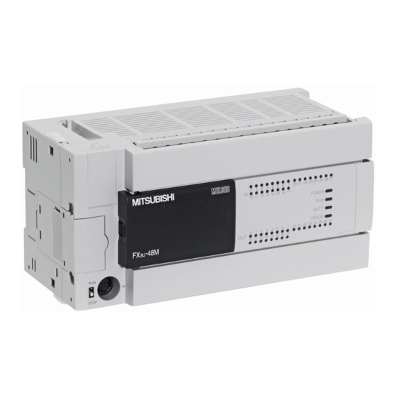
Page 30: Layout Of The Melsec Fx3U Base Units
Installation place for memory cassette Protective cover for Memory cassette expansion bus (optional) Expansion bus (lateral) Special adapter Connection for connector programming unit Connectors for Battery digital outputs Connectors for Battery cover digital inputs 2 - 12 MITSUBISHI ELECTRIC... -
Page 31: Wiring
The Hardware Wiring Wiring 2.7.1 Power Supply Power Supply Specifications Specification Units for DC Power Supply Units for AC Power Supply Rated voltage 12 to 24 V DC 24 V DC 100 to 240 V AC Voltage range 10.2 to 26.4 V DC 20.4 to 26.4 V DC 85 to 264 V AC Allowable momentary... -
Page 32: Wiring Of Inputs
Examples for input types AC powered base units Sink Source X000 X000 X001 X001 X002 X002 X003 X003 2 - 14 MITSUBISHI ELECTRIC... -
Page 33: Wiring Of Outputs
The Hardware Wiring DC powered base units Sink Source 24 V DC 24 V DC (0V) (0V) (24V) (24V) X000 X000 X001 X001 X002 X002 X003 X003 2.7.3 Wiring of Outputs In case of base units with only few outputs (e. g. FX -14M or FX -16M„) each output can... - Page 34 Wiring The Hardware Examples of output wiring Relay output Load Fuse Transistor output (sink) Load Fuse Transistor output (source) Load Fuse 2 - 16 MITSUBISHI ELECTRIC...
-
Page 35: Extending The Range Of Digital Inputs/Outputs
The Hardware Extending the Range of Digital Inputs/Outputs Extending the Range of Digital Inputs/Outputs For the MELSEC FX family of PLCs several ways and means are available to provide a base unit with additional inputs and outputs. 2.8.1 Extension Boards For a small number of I/O (2 to 4) an exten- -2EYT-BD sion adapter board can be installed directly in... -
Page 36: Modular Extension Blocks
-8ER-ES/UL occupies 16 input/output points of the PLC. Four inputs and four outputs are occupied but cannot be used. The FX series extension blocks can only be connected to a base unit of the FX or FX series. 2 - 18 MITSUBISHI ELECTRIC... -
Page 37: Extending For Special Functions
The Hardware Extending for Special Functions Extending for Special Functions A variety of hardware for special functions are available for the MELSEC FX family. Adapter Boards Adapter boards are small circuit boards that are installed directly in the FX , FX or FX con- trollers, which means that they don’t take up any extra space in the switchgear cabinet. -
Page 38: Analog Modules
4 µA (12 Bit) 4 mA to 20 mA DC The special function block FX -8AD is able to measure voltage, current and temperature. The FX -4AD can be connected to base units of the FX series only. 2 - 20 MITSUBISHI ELECTRIC... - Page 39 The Hardware Extending for Special Functions No. of Modul Type Designation Range Resolution channels Voltage: 5 mV -10 V to 10 V DC (with sign, 12 bits) -4DA Current: 0 mA to 20 mA DC 20 µA (10 Bit) Special 4 mA to 20 mA DC Function Voltage:...
- Page 40 The adapter board, special adapter or special function module can be used with a base unit or expan- sion unit of this series. The adapter board, special adapter or special function module cannot be used with this series. 2 - 22 MITSUBISHI ELECTRIC...
-
Page 41: High-Speed Counter Modules And Adapters
The Hardware Extending for Special Functions 2.9.2 High-Speed Counter Modules and Adapters -1HC, FX -1HC and FX -2HC In addition to the internal high-speed MELSEC FX counters, the high-speed counter modules -1HC, FX -1HC and FX -2HC provide the user with an external counter. They count 1- or 2-phase pulses up to a frequency of 50 kHz resp. -
Page 42: Positioning Modules
(by external regulator) with a pulse chain. They are very suitable for achieving accurate positioning in combination with the MELSEC FX series. The configu- ration and allocation of the position data are carried out directly via the PLC program. -
Page 43: Network Modules For Ethernet
The Hardware Extending for Special Functions 2.9.4 Network Modules for ETHERNET ETHERNET is the most widespread network for connection of information processors such as personal computers and work stations. By loading an ETHERNET interface into the PLC, pro- duction-related management information can be transmitted rapidly to personal computers or work stations. -
Page 44: Network Modules For Profibus/Dp
- 3 2 D P i s a PROFIBUS/DP slave module. It allows the integration of a , FX , or FX PLC into a PROFIBUS/DP RU N network. TO KEN FRO M/T O PO WE R FX -3 2D P 2 - 26 MITSUBISHI ELECTRIC... - Page 45 The Hardware Extending for Special Functions -64DP-M The FX -64DP-M PROFIBUS DP master module is available for the FX and FX base units and enables the attached FX base unit to be a master station on a RU N PROFIBUS DP-V1 network. PROFIBUS DP allows for the TO KEN FRO M/T O implementation of decentralized control with comprehen-...
-
Page 46: Network Modules For Cc-Link
Special function modules -32CCL Remote device station for CC-Link -64CCL The special function module can be used with a base unit or expansion unit of this series. The special function module cannot be used with this series. 2 - 28 MITSUBISHI ELECTRIC... -
Page 47: Network Module For Devicenet
The Hardware Extending for Special Functions 2.9.7 Network Module for DeviceNet DeviceNet represents a cost-effective solution for the network integration of low-level terminal equipment. Up to 64 devices including a master can be integrated in one network. For the data exchange a cable with two shielded twisted-pair cables is used. -
Page 48: Network Module For As-Interface
Master for Special function module -32ASI-M AS-i system The special function module can be used with a base unit or expansion unit of this series. The special function module cannot be used with this series. 2 - 30 MITSUBISHI ELECTRIC... -
Page 49: Interface Modules And Adapters
The Hardware Extending for Special Functions 2.9.10 Interface Modules and Adapters For serial data communication a large range of interface modules/adapters is available. Shown below are only some examples, but the following table covers all available interfaces. RS232C interface adapter board FX -232-BD Communication special adapter -232ADP (RS232C interface) -
Page 50: Communication Adapters
JY3 31B 892 01B -CNV-IF The FX -CNV-IF interface allows special function mod- ules of the old FX series to be connected to the base units of the FX family. MIT SUB ISH I FX -CN V-I F Overview of Communication Adapters... -
Page 51: Setpoint Adapter Boards
The Hardware Extending for Special Functions 2.9.12 Setpoint Adapter Boards These analog setpoint adapters enable the user to set 8 analog setpoint values. The analog val- ues (0 to 255) of the potentiometers are read into the controller and used as default setpoint val- ues for timers, counters and data registers by the user’s PLC programs. -
Page 52: System Configuration
. They cover networking functionality, analog control, pulse train outputs and tempera- ture inputs (for further details please refer to section 2.9). POWER 1 2 3 FX -16LNK-M FX base unit Special function modules Compact extension unit 2 - 34 MITSUBISHI ELECTRIC... - Page 53 The Hardware System Configuration Expansion Options Number of modules on the Number of boards in expan- Number of modules on the left side of base unit sion board port of base unit right side of base unit — The modules FX -485ADP and Up to 2 special function mod- -232ADP can be mounted...
-
Page 54: Connection Of Special Adapters
Communication or Base unit Possible interface adapter special adapter special adapter configuration board Illegal Communication Analog Base unit special adapter special adapter configuration These adapters do not function. No communication adapter board or interface adapter board 2 - 36 MITSUBISHI ELECTRIC... - Page 55 The Hardware System Configuration Combination of communication special adapters and an interface adapter board When instead of a communication adapter board FX -CNV-BD an interface adapter board 232-BD, FX -422-BD, FX -485-BD, or FX -USB-BD is mounted, one communication special adapter FX -232ADP or FX -485ADP may be used.
-
Page 56: Basic Rules For System Configuration
When also special function modules are added, calculate the current consumption to ensure that the total current to be consumed by the additional modules can be supplied by the built-in power supply. For details of the power consumption please refer to the appendix (section A.4). 2 - 38 MITSUBISHI ELECTRIC... -
Page 57: Quick Reference Matrixes
The Hardware System Configuration 2.10.3 Quick Reference Matrixes When only input/output extension blocks without a built-in power supply are added to a base unit, a quick reference matrix can be used. The following examples are valid for base units of the series. - Page 58 When adding 32 inputs to a DC powered base unit with 48, 64, or 80 I/Os, a maximum of 40 outputs are expandable. But when adding 32 inputs under the supply voltage 16.8 V to 19.2 V, a maximum of 24 outputs are expandable. 2 - 40 MITSUBISHI ELECTRIC...
-
Page 59: I/O Assignment
The Hardware I/O Assignment I/O Assignment 2.11 The assignment of the inputs and outputs in a PLC of the MELSEC FX family is fixed and can not be altered. When power is turned on after input/output powered extension units/blocks have been con- nected, the base unit automatically assigns the input/output numbers (X/Y) to the units/blocks. -
Page 60: Special Function Module Address
Input/output extension blocks (e. g. FX -16EX-ES/UL or FX -16EYR-ES/UL) – Communication adapter (e.g. FX -CNV-BD) – Interface adapter (e. g. FX -232-BD – Special adapter (e. g. FX -232ADP) – Extension power supply unit FX -1PSU-5V 2 - 42 MITSUBISHI ELECTRIC... -
Page 61: Programming
Programming Concepts of the IEC61131-3 Standard Programming Concepts of the IEC61131-3 Standard IEC 61131-3 is the international standard for PLC programs, defined by the International Elec- tromechanical Commission (IEC). It defines the programming languages and structuring ele- ments used for writing PLC programs. This system enables structured programs to be created using a high degree of modularisation. -
Page 62: Software Structure And Definition Of Terms
These modules are referred to as Program Organisation Units (POU’s), which form the basis of the new approach to programming PLC systems. Program organisation units (POU’s) are used to implement all programming tasks. 3 - 2 MITSUBISHI ELECTRIC... - Page 63 Programming Software Structure and Definition of Terms There are three different classes of POU’s, classified on the basis of their functionality: b Programs b Functions b Function Blocks POU’s declared as Function Blocks can be considered as programming instructions in their own right and they can be used as such in every module of your programs.
- Page 64 In this way, perhaps complicated interlocking routines, could be written in a ladder POU, whilst complex calculations or algorithms, might be better suited to one of the textual, or FDB editors. It is the choice of the designer/user but this environment allows flexibility. 3 - 4 MITSUBISHI ELECTRIC...
- Page 65 Programming Software Structure and Definition of Terms Above an example of the GX-Developer display is shown illustrating an example POU Pool. Composition of a POU Training Manual GX IEC Developer 3 - 5...
- Page 66 The Global Variable List (GVL) provides the interface for all names, which relate to real PLC addresses, i.e. I/O data registers etc. The GVL is available and can be read by all POU’s created in the project. 3 - 6 MITSUBISHI ELECTRIC...
- Page 67 Programming Software Structure and Definition of Terms Task Pool and Task Manager If we now think of our routines as POU’s written for each function and given names, we can cre- ate a Task for each of our assigned POU’s. Each Task can have different operating conditions, or events.
- Page 68 The Task Pool allows the user to efficiently manage the PLC scan, ensuring that only the rou- tines that require scanning are executed. It also provides an easy method of allocating specific routines to events and timed or priority interrupts. 3 - 8 MITSUBISHI ELECTRIC...
-
Page 69: System Variables
Programming Software Structure and Definition of Terms The software engineer need only be concerned about the program content, not whether the branch instructions are correct and obey the rules. Machines/processes, consisting of standard parts, can have individual POU’s written for each part. -
Page 70: System Labels
Event Driven Task (not EVENT = TRUE) b User Defined Function blocks (one per function block – unless macro code) b System Timers (These are used by the Task Manager, for interval triggered tasks and local Timers.) 3 - 10 MITSUBISHI ELECTRIC... -
Page 71: Programming Languages
Programming Programming Languages Programming Languages GX IEC Developer provides separate editors for all the following programming languages, which can be used to program the bodies of your programs: Text Editors b Instruction List (IEC and MELSEC) b Structured Text Graphic Editors b Ladder Diagram b Function Block Diagram b Sequential Function Chart... -
Page 72: Graphic Editors
Boolean input (EN = ENable) and output (ENO = ENable Out). The status at the input always corresponds to that at the output. Example for Ladder diagram 3 - 12 MITSUBISHI ELECTRIC... - Page 73 Programming Programming Languages Function Block Diagram All instructions are implemented using blocks, which are connected with one another with hori- zontal and vertical connecting elements. There are no power bars. In addition to the normal input and output parameters, some blocks also have a Boolean input (EN = ENable) and output (ENO = ENable Out).
- Page 74 Only one step in the sequence can be active at any one time. The next step is not activated before the previous step has been completed and the transition is satisfied. Example for Sequential Function Chart 3 - 14 MITSUBISHI ELECTRIC...
-
Page 75: Data Types
Programming Data Types Data Types GX IEC Developer supports the following data types. 3.4.1 Simple Types Data type Value range Size Applicable Devices / PLCs BOOL Boolean Bit Device 0 (False), 1 (True) 1 bit X, Y, M, B Integer -32768 to +32767 16 bit Register... - Page 76 Data Types Programming Two Dimensional Array Identifier Type Motor_Volt ARRAY [0..3, 0...3] OF INT = Motor_Volt [2, 3] Three Dimensional Array Type Identifier Motor_Current ARRAY [0..3, 0...2, 0..2] OF INT = Motor_Current [1, 2, 1] 3 - 16 MITSUBISHI ELECTRIC...
- Page 77 Programming Data Types Data Unit Types (DUT) User defined Data Unit Types (DUT), can be created. This can be useful for programs which contain common parts, for example; the control of six identical silos. Therefore a data unit type, called ‘Silo’ can be created, composing patterns of different elements, i.e. INT, BOOL etc. When completing a global variable list, identifiers of type Silo can be used.
- Page 78 (Silo_01 and Silo_02 ) of this function blocks were then created for two silos. The GVL has been extended to define addresses for all elements of data unit types. Not defined addresses are handled by the system. 3 - 18 MITSUBISHI ELECTRIC...
- Page 79 Programming Data Types To view all definitions at once (if more than one definition is available), DUT entries in the GVL can be expanded by double-clicking the row number field. Training Manual GX IEC Developer 3 - 19...
-
Page 80: Melsec Timers And Counters
System Variable default T/C usage: In the following example, the counter has been programmed using identifiers which would have to be declared in the Global and Local Variable tables: 3 - 20 MITSUBISHI ELECTRIC... -
Page 81: Building A Project
Building a Project Building a Project In the next section, we will build our first project, initially using the Ladder Diagram editor. Topics covered b Using the Project Navigator b Using the GVL with identifiers b Declaring variables in the Program Header b Creating programs with the IEC ladder editor b Programming IEC Timers/Counters b Commenting and Documentation... -
Page 82: Starting Gx Iec Developer
´ Editor (Body) In this area the POUs can be edited. Each POU consists out of a Header and a Body. 4 - 2 MITSUBISHI ELECTRIC... - Page 83 Building a Project Starting GX IEC Developer – Header A header is an integral part of a program organisation unit (POU). It is the place where the variables to be used in the POU must be declared. – Body A body is an integral part of a program organisation unit (POU). It contains the code ele- ments and syntax of the actual program, function block or function.
-
Page 84: Application Program
The design must therefore contain interlocks to prevent miss-operation as described above. An alternative approach to the design would suggest the use of ‘Pulse Transition Logic’ by means of the IEC or MELSEC “Edge Triggered” configurations. 4 - 4 MITSUBISHI ELECTRIC... - Page 85 Building a Project Application Program The most appropriate command to use in this application is the MELSEC ‘PLS’ (Rising edge Pulse). It has been adopted here instead of the IEC instruction R_TRIG (Rising edge Trigger) instruction, which would also be suitable. The following diagram illustrates the order of sequencing of the carousel control.
-
Page 86: Creating A New Project
Choose the appropriate PLC type from the selection: Provide a name for the project in the project path field. In this case use “\GXIEC DATA\CAROUSEL” and click on Create – as in the following illustration: 4 - 6 MITSUBISHI ELECTRIC... - Page 87 Building a Project Application Program The Wizard The Project Startup Wizard will be displayed: The Wizard provides a quick way to begin projects. It will thus create the basic starting structures for simple projects. Select the Option, Empty Project and click OK . This effectively inhibits the Wizard from creating any project elements.
-
Page 88: Creating A New "Pou
Click OK and note the addition to the POU Pool in the ‘Project navigation window’: Double click on MAIN program icon or click the symbol on the POU Pool in order to expand the directory branch and display the Header and Body entries: 4 - 8 MITSUBISHI ELECTRIC... -
Page 89: Assigning The Global Variables
Building a Project Application Program 4.2.4 Assigning the Global Variables Before any program code can be created, it is necessary to specify and assign all pre-allocated physical PLC inputs and outputs including any shared variables that are to be used in the pro- ject. - Page 90 If symbolic identifiers are not to be used in the program but only Mitsubishi addresses, then there is no need to fill out the Global Variable List (GVL). However the program will no longer be truly IEC61131-3 compliant. 4 - 10 MITSUBISHI ELECTRIC...
- Page 91 Building a Project Application Program Fill out the table as shown in the following illustration. The variable “Type Selection” is automati- cally recognised and placed by GX IEC Developer upon entry of the ‘Address’ but can be input manually or modified by clicking on the type select arrow in the Type field area. When the Mitsubishi address is entered, the system automatically converts and enters the IEC equivalent.
- Page 92 , FX , System Q and AnA(S) type CPU’s IEC Type REAL (Float- ing Point) values are fully supported. When the data entry in the GVL has been completed, click the ‘Check’ button as shown: 4 - 12 MITSUBISHI ELECTRIC...
- Page 93 Building a Project Application Program Opening the POU Header From the Project Navigation window, double click on the Header on the POU MAIN . The following screen will be displayed: Close this POU Header display. Training Manual GX IEC Developer 4 - 13...
-
Page 94: Programming The Pou Body
Application Program Building a Project 4.2.5 Programming the POU Body To open the Ladder diagram editor, double click on the Body selection under the POU pool in the project navigation window: The following window is displayed: 4 - 14 MITSUBISHI ELECTRIC... - Page 95 Building a Project Application Program With the pointer over the window boundary, click and drag downwards to increase the ver- tical size of the network: Using the Toolbar Ladder Symbol Selection With the editor in “Selection Mode”, select the ‘Normally Open’ contact from the toolbar: Move the mouse pointer over the work area and click to fix the drop position on the window: Training Manual GX IEC Developer 4 - 15...
- Page 96 Note that the current ‘Header’ should be selected under the Scope dialogue area. Click “Foot_Switch” to highlight that variable and click the Apply button. Then close the Variable Selection box. 4 - 16 MITSUBISHI ELECTRIC...
- Page 97 Building a Project Application Program Alternative Variable Specification Method: Editing in Split Screen Split screen viewing of POU Ladder diagram and Header is possible by opening both the header and the ladder and selecting “Tile Horizontally.” Continue editing Project ‘Carousel’ Enter the normally open contact of the “In_Position_Sensor"...
- Page 98 The MELSEC Function Block command, ‘PLS_M’ will be added to the program as the output function. Click on the Function / Function block selection button on the tool bar. On the Opera- tor type click Functions and type "PLS_M" into the Operators prompt box thus: 4 - 18 MITSUBISHI ELECTRIC...
- Page 99 Building a Project Application Program Assigning a Variable to an Instruction Click on the output variable prompt from the toolbar. Click on the ‘d’ destination, output function from the PLS_M to drop the variable prompt field. Enter the variable name Ft_Sw_Trig into the empty ‘?’ box. The following prompt is displayed if the variable does not exist in the Local Variable List ‘LVL’...
- Page 100 On the Ladder diagram click on the left point on the ladder diagram and “Click – Drag” across the diagram and release on the ‘EN’ input on the ‘PLS_M’ function as shown below: The circuit is now complete. 4 - 20 MITSUBISHI ELECTRIC...
- Page 101 Building a Project Application Program Changing the cursor mode Before continuing with the worked example, it is necessary to understand the operation of the cursor control and the various edit modes that are available. The following text is for illustration purposes only: While in the ladder edit screen, Right clicking the mouse button pops up a small selection win- dow as shown below.
- Page 102 To create a network below the current one, click the ‘insert after’ button. A blank net- work space will appear: Enter the second network in the same format as previously described with the following attributes: 4 - 22 MITSUBISHI ELECTRIC...
- Page 103 Building a Project Application Program Finally, enter the following network as shown: Checking the entered Program When the three networks have been entered, complete click the Check button and if all is well, the following dialogue is displayed: Adding new POU’s – Counters and Timers Continuing with the Carousel example;...
- Page 104 Project Navi- gation Window. As discussed previously, the ladder network may be re-sized by moving the mouse pointer to the lower boundary of the network header and ‘click-hold’ dragging downward to increase the vertical size: 4 - 24 MITSUBISHI ELECTRIC...
- Page 105 Building a Project Application Program Counting function Using the editor in “select” mode, enter the instruction CTU (Count Up) into the ladder network: Drop the IEC Function Block onto the empty Ladder network: Instances of Function Blocks Function Blocks can only be called as “Instances.” The process of “Instancing,” or making a copy of a function block, is performed in the header of the POU in which the instance is to be used.
- Page 106 Adding entries to the GVL Note, in particular: “Reset_In” (Global) - is a new Input mapped from the MELSEC boolean address X02 or IEC %IX2. This requires a new entry into the GVL as follows: 4 - 26 MITSUBISHI ELECTRIC...
- Page 107 Building a Project Application Program When all new entries are complete, click the check button then the ‘Rebuild All’ button to check and assemble the project. Timing Function Create the following Ladder Networks below the batch counting routine in the Batch_Count POU as shown: When the editing task has been completed, the GVL should appear thus: The header (LVL) for the above program “Batch_Count”...
- Page 108 Application Program Building a Project When all new entries are complete, click the check button then the ‘Rebuild All’ button to check and assemble the project. For the POU, “Batch_Count” header For the POU, “MAIN” header: 4 - 28 MITSUBISHI ELECTRIC...
-
Page 109: Creating A New Task
Building a Project Application Program 4.2.6 Creating a new Task In order for the POUs “MAIN” and "Batch_Count" to be assembled and executed in the PLC, they must be specified as valid tasks in the Task Pool . Click once to highlight the TASK_Pool icon in the Project Navigation area. - Page 110 Double click the Control1 Task icon in the Project Navigation Window; the ‘task event list’ window will be displayed: Click on the centre ‘choice browse’ ellipsis as shown above. The following prompt dialogue is displayed: Choose MAIN and click OK to complete the assignment operation. 4 - 30 MITSUBISHI ELECTRIC...
- Page 111 Building a Project Application Program Task Properties The properties for the task can be displayed by right clicking the mouse on the required task pool entry (i.e. Control1) and selecting Properties from the menu. The following task settings win- dow is displayed: b Task Attributes –...
- Page 112 When complete, click the check button then the ‘Rebuild All’ button to check and assemble the project. Save the project using the save button. The project is now complete and must therefore be transferred to the PLC. 4 - 32 MITSUBISHI ELECTRIC...
-
Page 113: Program Documentation
Building a Project Application Program 4.2.7 Program Documentation Network Header Titling the network header is optional and provides a means to identify the program network with a descriptive title of up to 22 characters. This can assist handling projects where large numbers of networks are present. -
Page 114: Checking And Building The Project Code
When the Ladder Diagram is complete and task has been specified in the Task Pool, once again press the “Check” button on the tool bar to check the program for errors; the fol- lowing dialogue should be displayed: 4 - 34 MITSUBISHI ELECTRIC... - Page 115 Building a Project Application Program Click either the ‘Build’ button or the ‘Rebuild All’ button on the toolbar and if all is well, the following compiler messages are reported: Click Close to exit this display. Training Manual GX IEC Developer 4 - 35...
-
Page 116: Illustration: Guided Ladder Entry Mode
Select the ‘Normally Open’ Contact symbol “1” and the following will be displayed: The program may continue to be entered using the “F2” button on the keyboard or click on the button on the tool bar to call up the variables selection window as previously described. 4 - 36 MITSUBISHI ELECTRIC... -
Page 117: Project Download Procedures
Building a Project Project Download Procedures Project Download Procedures 4.3.1 Connection with Peripheral Devices The following notes describe how the project is downloaded to a FX PLC. To connect a controller of the FX family and a PC, the SC 09 converter is used to convert the RS232 common mode serial signals ‘to and from’... - Page 118 Project Download Procedures Building a Project Double click the mouse on the yellow PC side I/F – Serial button and the following dia- logue window is displayed: Select RS232C as shown above and click OK . 4 - 38 MITSUBISHI ELECTRIC...
- Page 119 Building a Project Project Download Procedures Click on the Connection Test button to check PC-PLC communications are ok: The following message should be displayed: Click OK to close this message. If an error message is displayed, check connections and settings with the PLC. Training Manual GX IEC Developer 4 - 39...
- Page 120 Select OK to close the System image display and return to the Connection setup dis- play. Than click the OK button to close the Connection Setup window. If you leave the Connection Setup window using the Close button, the settings are not saved. 4 - 40 MITSUBISHI ELECTRIC...
-
Page 121: Downloading The Project
Building a Project Project Download Procedures 4.3.3 Downloading the project Once the setting up procedures is complete, click on the “Download Project” icon on the toolbar. Transfer Setup Click the Configure button to setup the “Transfer parameters” for the project. Click on PLC-Parameter and Program Click on OK to confirm the selection. - Page 122 Project Download Procedures Building a Project To send the project to the PLC, click the OK button to execute the transfer. 4 - 42 MITSUBISHI ELECTRIC...
-
Page 123: Monitoring The Project
Building a Project Monitoring the Project Monitoring the Project Ensure that the PLC is switched to RUN and no errors are present. Display the body of the MAIN ladder program. Click on the Monitor Mode Icon on the toolbar and observe the ladder display: NOTE Depending on the colour attributes set, monitored variables will be displayed with a coloured surround (Default: Yellow). -
Page 124: Split / Multi Window Monitoring
To begin monitoring the content of additional windows, click inside that window and select Start Monitoring from the Online Menu: NOTE Due to the serial communications handshake, be prepared to wait a few seconds for the monitor information to be registered between GX IEC Developer and the PLC. 4 - 44 MITSUBISHI ELECTRIC... - Page 125 Building a Project Monitoring the Project The rate of communication polling from GX IEC Developer to the PLC may be increased by adjusting the poll rate setting. Select Monitor Mode from the Extras / Options menu and enter a new value for the Poll rate . Training Manual GX IEC Developer 4 - 45...
-
Page 126: Adjusting Monitor Visibility
To adjust the visibility of the monitor mode, select ‘Extras/Options/Monitor Indication’ and a flashing message can be enabled, to appear where chosen. The blink rate of the “Monitoring” banner can be set by the User: 4 - 46 MITSUBISHI ELECTRIC... -
Page 127: Cross Reference List
Building a Project Cross Reference List Cross Reference List To generate a Cross Reference List: Open the Extras / Options Menu and select Cross Reference Check both options shown and re-compile the project. Then select Make Cross Reference from the Project Menu and the list is generated. - Page 128 Click on the Search button and the full list will be displayed. Specific variables etc. can be searched by using the query selection boxes. Individual details of the highlighted entry are then shown on the right hand side of the window. 4 - 48 MITSUBISHI ELECTRIC...
- Page 129 Building a Project Cross Reference List The Show in Editor button opens the header of the highlighted right hand list element, for example: Object highlighted The Cross Reference List may be printed out, using the print facility within GX IEC Developer. Training Manual GX IEC Developer 4 - 49...
-
Page 130: Plc Diagnostics
User errors can be determined. These user errors are stored with a self-created text file (USER_ERR.TXT) and allow a quick error correction. The last eight user errors are stored into a FIFO register and only be removed when they no longer occur. 4 - 50 MITSUBISHI ELECTRIC... -
Page 131: Project Documentation
Building a Project Project Documentation Project Documentation Project documentation can be set up using the Print Option facility from the Project Menu: The “Change Configuration” dialogue box can then be seen. Previous project profiles can be retrieved here, or work with the default profile. Either select the Project Tree for all elements, or Selected Items for specific highlighted items, open Properties : Training Manual GX IEC Developer 4 - 51... - Page 132 In this example, only the COUNTER_FB_CE will be printed, as the Selected Items option was chosen: User defined logos and information can be assigned, in the Cover Page tab, for the front sheet and for the frame from the Frame Logos tab: 4 - 52 MITSUBISHI ELECTRIC...
- Page 133 Building a Project Project Documentation Detailed information can be assigned, to the left and right footers. The field labels in the Left Footer dialogue can be renamed, by clicking on the name buttons, as required: Specification for POU appearance and general project specifications are available from the POUs and General/Project Tree tabs.
- Page 134 SFC and Cross Reference tabs: The configured profile can be saved, by simply naming the Current Profile field and then click- ing the Save button. It can then be recalled at any time using the selection box: 4 - 54 MITSUBISHI ELECTRIC...
-
Page 135: Program Example
Program Example An Alarm System Program Example An Alarm System Task description The objective is to create an alarm system with several alarm circuits and a delay function for arming and disarming the system. – The system will be armed after a delay between turning the switch and activation. This pro- vides time for the user to leave the house without tripping the alarm. -
Page 136: Method
Enter the following data into the Global Variables List : Create a new POU of Class PRG (Program Type) and Language Ladder Diagram . Enter the following code into the POU. To be continued on the next page 5 - 2 MITSUBISHI ELECTRIC... - Page 137 Program Example An Alarm System The finalised header of the “Main_PRG_LD” POU should read as follows Training Manual GX IEC Developer 5 - 3...
-
Page 138: Checking The Example Program "Alarm_System
Enter and comment the project. Check the program using the function provided in the tool bar. Build and save the project. Download the project to the FX series PLC. Activate the monitor mode to observe the function of the program. -
Page 139: Functions And Function Blocks
Functions and Function Blocks Functions Functions and Function Blocks Below is a table illustrating the comparison between ‘Functions’ and ‘Function Blocks’: Item Function Block Function Internal variable storage Storage No storage Instancing Required Not required No output Outputs One output One output Multiple outputs Repeated execution with same input... - Page 140 Select Function Block Diagram as the editor. The Result Type of FUN should be left as INT (Integer type). Centigrade will now have appeared on the POU tree: Double click on the FBD body icon, to open the body network: 6 - 2 MITSUBISHI ELECTRIC...
- Page 141 Functions and Function Blocks Functions Selecting the Function: Select the function block icon from the toolbar and select SUB from the operators list: Using Appl y or double clicking on the selection object, place it on the screen: Repeat the above process so that the following is visible: Training Manual GX IEC Developer 6 - 3...
- Page 142 (LVL), a prompt dialogue will be presented to choose Global or Local vari- able, click Define Local . Fill out the properties of the variable thus: Class: VAR_INPUT, Type: INT, as shown below: 6 - 4 MITSUBISHI ELECTRIC...
- Page 143 Functions and Function Blocks Functions NOTES The Class VAR_INPUT is required as this variable enables values to be input into the func- tion when it is connected as part of a program. It will produce a left hand pointing input con- nection point on the function symbol.
- Page 144 Check the Network; you should have no errors and no warnings! Close down all work windows and any dialogues that may be open. Creating a New Program POU Create a new POU called “Process” of Class “PRG” with a language of Function Block Diagram “FBD”: 6 - 6 MITSUBISHI ELECTRIC...
- Page 145 Functions and Function Blocks Functions Open up (Double Click) the body of Ladder POU “Process” in the project POU pool. Placing a user Function Click on the Function Block icon again, but this time select Functions and select the Project Library . Notice the newly created function “Centigrade” is now filtered down into the operators list: Select CENTIGRADE and click ‘Apply’.
- Page 146 The Body of the POU “Process" should read: Create a new task in the Task Pool named “Main”. Bind the POU “Process” to the Task “Main”: Compiling the Program Compile the project using the Rebuild All operation from the tool bar: 6 - 8 MITSUBISHI ELECTRIC...
- Page 147 Functions and Function Blocks Functions Following compilation the following should be displayed: If there are errors, click on the error detail and resolve the problem(s). Monitoring the program Transfer the project to the PLC and monitor this network using the Monitor button the toolbar: Using the on screen variable forcing feature, input numbers into the ‘Deg_F’...
-
Page 148: Processing Real (Floating Point) Numbers
Right Click on the CENTIGRADE Icon in the POU Pool of the project and select Copy . Right Click on the POU pool icon of the project and select Paste . The system will automatically paste a duplicate copy of ‘CENTIGRADE’ and rename it to ‘CENTIGRADE1’: 6 - 10 MITSUBISHI ELECTRIC... - Page 149 Functions Functions and Function Blocks Changing the Result type of a Function Right click on the newly created Function ‘CENTIGRADE1’ and click on Properties . On displaying the Function Information window, set the result type to REAL. The type should now displayed as Real in the Project Navigation Window: Modify the Header of CENTIGRADE1 so that the Fahrenheit variable is of type ‘REAL’: Training Manual GX IEC Developer 6 - 11...
- Page 150 Open the Body of POU “Process” and place the Function CENTIGRADE1 into it as shown below: NOTE REAL numbers use 2 consecutive Registers (32 Bits) and are stored in a special portable IEE format, hence the allocation in the above GVL example. 6 - 12 MITSUBISHI ELECTRIC...
- Page 151 Functions Functions and Function Blocks Complete the POU “Process” to read as follows: Save the Project, Close all open dialogues and rebuild the project. Transfer the project to the PLC and monitor this network using the Monitor button on the toolbar: Modify the value of the input variable “Deg_F_Real”...
-
Page 152: Creating A Function Block
STAR_DELTA will now have appeared on the POU tree. Click once to open the Header and Body branches. Double click, to open the Header. Declaring Local Variables Declare variables as shown below. Check, save and then close the Header window. 6 - 14 MITSUBISHI ELECTRIC... - Page 153 Creating a Function Block Functions and Function Blocks Open the body and build the ladder networks as shown below: Check the Body, there should be no errors and no warnings! Training Manual GX IEC Developer 6 - 15...
- Page 154 Open the GVL and enter the following I/O details: Assigning Instance Names Open the Body of MOTOR_CONTROL and enter create two networks. Place a Instance of the Function Block STAR_DELTA into each network as shown in the following figure: 6 - 16 MITSUBISHI ELECTRIC...
- Page 155 Creating a Function Block Functions and Function Blocks A s s i g n ‘ i n s t a n c e n a m e s ’ t o b o t h i n s t a n c e s o f t h e F u n c t i o n B l o ck , STAR_DELTA by typing MCC1 and MCC2 into the Instance names above each Instance of the FB.
- Page 156 Designating the variable “TRUE” as above, automatically assigns a ‘normally on’ contact (Special relay M8000 in MELSEC FX series) which is neater and conforms to IEC conventions. The STAR_DELTA FB can be used many times in the project and must use different Instance names.
- Page 157 Creating a Function Block Functions and Function Blocks Double click on the task and bind the POU “MOTOR_CONTROL” to the task “MAIN”: Save the Program, close all windows and dialogues. Find unused Variables By using the function Extras ® Find unused Variables you can find and delete all unused global and local vari- ables that are declared but not used in a project.
- Page 158 Symbolic (Source) Code to the PLC has been selected for download: Compile the program in the normal manner, using the “Rebuild All” button on the toolbar: Open the MOTOR_CONTROL POU and monitor the program for correct operation. 6 - 20 MITSUBISHI ELECTRIC...
-
Page 159: Execution Options Of Function Blocks
Execution Options of Function Blocks Functions and Function Blocks Execution Options of Function Blocks Function blocks can be executed in different ways: b Macrocode execution b MC – MCR execution b Use with EN/ENO The execution mode is selected in the Function Information dialogue box: How to set the execution option: Select the function block in the Project Navigator window. -
Page 160: Enable / Enableoutput (En/Eno)
All devices suffixed “_M” are manufacturers instructions, i.e. in this case from the relevant Mitsubishi instruction set. Exercise (Gated Operation) Edit the Function Block STAR_DELTA to have an EN/ENO input/output feature. Drive the EN (enable) input with external MELSEC X07 contact: 6 - 22 MITSUBISHI ELECTRIC... -
Page 161: Advanced Monitoring Functions
Advanced Monitoring Functions Entry Data Monitoring Advanced Monitoring Functions The following diagrams are used for illustration purposes only; use the STAR_DELTA project and its relevant devices with the following procedures. Entry Data Monitoring Whilst in Monitor Mode, select Entry Data Monitor from the Online Menu: The following table will be displayed: Training Manual GX IEC Developer... -
Page 162: Customising The Edm
Then press the left mouse button and move the border to the left or right. Release the left mouse button at the desired position. 7.1.1 Customising the EDM Right Clicking the mouse button, displays the following window. Select Setup . 7 - 2 MITSUBISHI ELECTRIC... - Page 163 Advanced Monitoring Functions Entry Data Monitoring The Setup window allows the EDM to be user configurable; clicking the right mouse button, dis- plays the configurator window. In this procedure Columns will be added to the EDM table for IEC Address and Hex Value Monitor. Highlight or right click on the Name field and select Insert Row as shown.
-
Page 164: Monitor Limitations
PLC; if the PLC code is writing a constant to this address, the value entered will be overwrit- ten by the program. This situation is prevalent here as the values of D0 and D1 are being con- tinuously written to by the PLC code. 7 - 4 MITSUBISHI ELECTRIC... -
Page 165: Toggling Boolean Variables
Advanced Monitoring Functions Entry Data Monitoring 7.1.3 Toggling Boolean Variables Providing the physical input to the PLC is not active, it is possible to toggle the input image in the CPU on and off by double clicking on the value field for that Boolean addresses as shown: Training Manual GX IEC Developer 7 - 5... -
Page 166: Monitoring Headers
Online menu. It is also available from the Online Toolbar All elements of the Header identifiers of the highlighted POU are now displayed and monitored: Note that the Boolean variables in the EDM are shown highlighted, when monitoring. 7 - 6 MITSUBISHI ELECTRIC... -
Page 167: Monitor Mode Essentials
Advanced Monitoring Functions Monitor Mode Essentials Monitor Mode Essentials Multiple Windows may be monitored simultaneously by first opening them separately and using ‘Tile Windows’ feature in the Window Menu. It is important to realise when first entering Monitor mode, only the target window in view will be monitored. Further windows may be monitored by first bringing them into the target view and clicking individually on the Start Monitoring (Ctrl+F8) selection from the Online menu:... - Page 168 Monitor Mode Essentials Advanced Monitoring Functions Simultaneous Monitoring of Header and Body Here is an example of Monitoring a POU and its header simultaneously: 7 - 8 MITSUBISHI ELECTRIC...
-
Page 169: Monitoring Mitsubishi "Transfer Form" Objects
Advanced Monitoring Functions Monitoring Mitsubishi “Transfer Form” Objects Monitoring Mitsubishi “Transfer Form” Objects It is also possible to monitor using the Mitsubishi Kn (Official – ‘Transfer Form’) notation for Boolean objects. For example K1X0 monitors X0 - X3 as shown in the following example: Setup Options Don’t Search Variables in GVL - if a direct Mitsubishi address is entered into the Entry Data Monitor (EDM), for example M0 the system automatically searches the GVL for the identifier. -
Page 170: Modifying Variable Values From The Pou Body
When using the Ladder editor, hold down the CTRL key and double click on the variable name. The actual address of the selected GV will then be displayed, as shown below. Repeating the operation will toggle back to the identifier. If Monitor Mode is stopped, then started again, identifiers are displayed. 7 - 10 MITSUBISHI ELECTRIC... -
Page 171: Monitoring "Instances" Of Function Blocks
Advanced Monitoring Functions Monitoring “Instances” of Function Blocks Monitoring “Instances” of Function Blocks Individual “Instances” of Function Blocks may be monitored independently. To monitor an instance of the POU FB STAR_DELTA in the current project, open the POU Body and click on the Monitor mode button. - Page 172 Monitoring “Instances” of Function Blocks Advanced Monitoring Functions 7 - 12 MITSUBISHI ELECTRIC...
-
Page 173: Device Edit
Device Edit Device Edit The Device Edit function is used to edit batch devices. Select Device Edit from the Debug menu. Highlight the cell in the top left hand corner. Click the right mouse button and then select Insert Devices : Training Manual GX IEC Developer 8 - 1... - Page 174 The device table can be configured as you wish and can be stored, as a file or written to the PLC. Information can also be uploaded from the PLC and displayed as below. The right mouse button supports many editing functions, find and replace, copy / paste, etc. 8 - 2 MITSUBISHI ELECTRIC...
- Page 175 Device Edit Highlight a row by clicking on the left hand box, i.e. “D0” Select Display Mode : This window allows the display format to be changed - try HEX . It should be noticed that the selected row now displays values in hexadecimal, the other values remain unchanged.
- Page 176 Device Edit 8 - 4 MITSUBISHI ELECTRIC...
-
Page 177: Online Mode
Online Mode Online Change Mode Online Mode There are two methods for evoking online editing; via the online menu or the toolbar icon. Use Save as in the Project menu to create a copy of the current project. Rename the Copy to “Motor_Control_Mod”. - Page 178 PLC automatically following a prompt to carry out or abort the action: NOTE Online editing is only allowed if the code is identical in the resident project and PLC. Enter Monitor mode and observe the operation of the modified block: 9 - 2 MITSUBISHI ELECTRIC...
-
Page 179: Online Program Change
Online Mode Online Program Change Online Program Change Where complete networks are to be added or removed, the “Online Program Change” operation must be used. This method is the preferred method of making changes to the program whilst on-line. For example: If the recently added counter network is to be removed from the program, carry out the following procedure (Remember the PLC and GX IEC Developer programs must be identical before proceeding). - Page 180 The system will prompt to continue or abort the process at this point. Click Yes and wait for the download synchronisation process to complete: Confirm correct operation by entering Monitor mode in the active POU. 9 - 4 MITSUBISHI ELECTRIC...
-
Page 181: Data Unit Types (Dut)
Data Unit Types (DUT) Data Unit Types (DUT) The following example illustrates the operation of DUT (Data Unit Types). The previous “Motor Control” example will be used to illustrate the procedures for creating and using DUT’s. User defined Data Unit Types (DUT), can be created. This can be useful for programs which contain common parts, for example;... -
Page 182: Example Use Of A Dut
Alternatively, ‘Copy-Paste’ the original function block, ‘Body and Header’, from the project “Motor Control” as follows: Body: STAR_DELTA Header: STAR_DELTA The Header contains the definitions (Mask) of the data types that will be used when creating the DUT “SD”. 10 - 2 MITSUBISHI ELECTRIC... - Page 183 Data Unit Types (DUT) Example use of a DUT Create a new DUT by right clicking on the DUT Pool icon in the Program navigation window or from the DUT icon on the toolbar. Enter the new DUT name as SD at the prompt. The new DUT will now be displayed under the DUT Pool in the project.
- Page 184 Type as “Data Unit Types” SD for both entries: Next, click on the MIT-Addr . cell for STAR_DELTA1 to enter the variable data for the selected DUT entry: Click to select Resulting window: 10 - 4 MITSUBISHI ELECTRIC...
-
Page 185: Automatic Filling, Variables
Data Unit Types (DUT) Automatic Filling, Variables Automatic Filling, Variables 10.2 Deselect All types as this operation is illegal when using mixed variable types. Enter Y00 in the MIT-Addr. position for the variable: ‘DELTA’: The system will try to sequentially ‘Auto Fill’ the variables of type BOOL. Although in many situa- tions this is recommended, in this case it is only partially successful. - Page 186 D0 and D1 using the “Auto Fill” feature: Click OK to save the current configuration. Repeat this series of operations for “STAR_DELTA2” entering the next sequential head address for each variable “TYPE”: Examine the GVL, it should read as follows: 10 - 6 MITSUBISHI ELECTRIC...
- Page 187 Data Unit Types (DUT) Automatic Filling, Variables Open the MOTOR_CONTROL program POU and place 2 instances of the user created Func- tion Block STAR_DELTA as shown: Training Manual GX IEC Developer 10 - 7...
-
Page 188: Assigning Dut Variables To Function Blocks
...right Click on a variable (or F2). The following variable selection window appears: Set the Scope to Header , Type Class to Data Unit Types and Type to ANY_DUT . Double Click on +STAR_DELTA1 and the following expanded DUT variable list appears: 10 - 8 MITSUBISHI ELECTRIC... - Page 189 Data Unit Types (DUT) Assigning DUT Variables to Function Blocks Pick and assign the variables to the two STAR_DELTA Function Blocks on the MOTOR_CONTROL Program POU as shown: Save the project and Rebuild All to compile the code: Download and monitor the project. Before the Function Blocks can operate, it is necessary to write values into the TIMEBASE inputs: STAR_DELTA1.TB and STAR_DELTA2.TB.
- Page 190 Assigning DUT Variables to Function Blocks Data Unit Types (DUT) 10 - 10 MITSUBISHI ELECTRIC...
-
Page 191: Arrays
Arrays Overview Arrays Overview 11.1 An array is a field or matrix of variables, of a particular type. For example, an ARRAY [0..2] OF INT, is a one dimensional array of three integer elements (0,1,2). If the start address of the array is D0, then the array consists of D0, D1 and D2. Identifier Address Type... - Page 192 Overview Arrays Three Dimensional Array Identifier Type Motor_Current ARRAY [0..3, 0...2, 0..2] OF INT = Motor_Current [1, 2, 1] 11 - 2 MITSUBISHI ELECTRIC...
-
Page 193: Array Example: Single Dimension Array
Arrays Array Example: Single Dimension Array Array Example: Single Dimension Array 11.2 The following example is used to illustrate a single dimension array. The array is 10 words long and uses Global MELSEC addresses D100 to D109. This example uses only “Standard IEC” Operators, Functions and Function Blocks. - Page 194 Define the ‘R_Trig’ Function block with instance name “Trigger”. Check the Header reads as shown below: Save the program and use Rebuild All to compile the program. Transfer the program to the PLC. Monitor the POU body (see next page). 11 - 4 MITSUBISHI ELECTRIC...
- Page 195 Arrays Array Example: Single Dimension Array Before the program is able to function as intended it is necessary to input data into the physical MELSEC addresses occupied by the array variables. There are two ways in which this may be achieved: b Use the Device Edit feature from the Debug menu as previously described, using Insert Devices in the range D100 to D109, and enter any 10 random integer values between...
- Page 196 “+“ prefix. Clicking on the variable name expands the array details into the table as shown: – Clicking on the “-“ Prefix collapses the array details. – While monitoring the variable values, enter any 10 random integer values between -32768 to +32767 as shown below: 11 - 6 MITSUBISHI ELECTRIC...
- Page 197 Arrays Array Example: Single Dimension Array – Switch back to monitor the body of the POU “Data_Lookup1” and observe the operation of the program, noting how the value alters on the output variable “Data_Lookup” as the data pointer increases: b The program is designed to reset the pointer to zero on the 10 element and thus will repeat scan the table with an upward increment (Index 0-9).
- Page 198 Array Example: Single Dimension Array Arrays 11 - 8 MITSUBISHI ELECTRIC...
-
Page 199: Working With Libraries
Working with Libraries User Defined Libraries Working with Libraries User Defined Libraries 12.1 All Functions and Function Blocks, created so far, have been resident in the current project and only available to that project. User defined libraries, allow the creation of libraries containing user created POU’s, Functions, Function Blocks etc. - Page 200 In this case it is suggested that the default path is used. This being: “C:\MELSEC\GX IEC DEVELOPER 7.00\Userlib”. Click Open when done: Notice the new Library “MCC_Programs” that is now present in the project Library Pool. 12 - 2 MITSUBISHI ELECTRIC...
-
Page 201: Opening The Library
Working with Libraries User Defined Libraries 12.1.2 Opening the Library Open the Library by right clicking on the icon ‘MCC_Programs’ and click on Open from the menu: The Library is now open and may be accessed and edited: Training Manual GX IEC Developer 12 - 3... -
Page 202: Moving A Pou "Function Block" To An Open Library
The Function Block STAR_DELTA will now be moved into the Library ‘MCC_Programs’. Right click on the STAR_DELTA icon in the Project navigation window and click on Cut : The following dialogue will be displayed: Select Yes 12 - 4 MITSUBISHI ELECTRIC... - Page 203 Working with Libraries User Defined Libraries Right Click on the User Library icon and select Paste from the menu: Click on the ‘+’ on the new entry in the Library POU Pool to expand the ‘STAR_DELTA’ Function Block: The Function Block POU, “STAR_DELTA” is now present in the Library “MCC_Programs” and no longer in the Project POU Pool.
- Page 204 The following message will be displayed: Click Yes and the library will be updated, saved and closed. The library is now stored in the default location of “C:\MELSEC\GX IEC DEVELOPER 7.00\Userlib” as set when creating the library. 12 - 6 MITSUBISHI ELECTRIC...
-
Page 205: Special Note About Libraries
Working with Libraries Special Note about Libraries Special Note about Libraries 12.2 Training Manual GX IEC Developer 12 - 7... -
Page 206: Importing Libraries Into Projects
Once ‘User Libraries’ have been created, it is possible to re-use routines by importing them into other applications. Mitsubishi Electric has produced many Libraries of commonly used routines. For example, ‘Intelligent Module’ interfaces such as A/D and D/A Function Blocks containing all the code to facilitate a working interface for these and many more modules. - Page 207 Working with Libraries Importing Libraries into Projects Next click OK to accept the entries. NOTE The help path is used for user help files that can be created in order to describe the operation of routines held in the library. These files can be created in MS-Word, for example in HTML format and manually saved with the reserved extension *.CHM.
- Page 208 Importing Libraries into Projects Working with Libraries Open the new POU and select the Function Block as shown: As can be seen the new library appears in the domain and may be selected as shown: 12 - 10 MITSUBISHI ELECTRIC...
-
Page 209: Importing A Mitsubishi Library Function Block
Working with Libraries Importing Libraries into Projects 12.3.2 Importing a Mitsubishi Library Function Block The following illustrations demonstrate the procedures required to import a Mitsubishi function block for analogue input using a module FX -4AD. This function block is provided by Mitsubishi. In order for the following example to function cor- rectly, it is necessary to install the library "AnalogFX"... - Page 210 Note the new “AnalogFX_V310” library in the Project Navigation Window. Create a new task in the task pool: “MAIN” and bind the POU “Analogue_Input” to it. Place the FX3U_4AD_ADP function block into the POU as shown below: 12 - 12 MITSUBISHI ELECTRIC...
- Page 211 Working with Libraries Importing Libraries into Projects The function block will appear thus: Define all variables as below: The outputs were registered as Global Variables. The instance name "ReadAverageValues" was assigned and defined as local variable. Compile and download the program to the PLC. Monitor and test for correct operation.
-
Page 212: Library Function Block Help
For example, the help screen for the FX3U_4AD_ADP function block looks as follows: The help files cover every aspect from the setup of the FX family analogue hardware modules to use of the library function blocks. 12 - 14 MITSUBISHI ELECTRIC... -
Page 213: Security
Security Password Security Password 13.1 You can protect all or parts of the program with a password. You can protect against editing of program parts and also protect circuits from being viewed by others. This is particularly relevant for user defined function blocks. In addition, the PLC password (Keyword) is also available. 13.1.1 Setting the Password Passwords can be entered and security levels can be... -
Page 214: Changing The Security Level
Enter the password for ‘Level 7’ and if accepted, the user will be logged on at this level. Once logged on, the security attributes for many items may be altered. For example one of the most common security options is to change access to POU’s, i.e. User Functions and Function Blocks. 13 - 2 MITSUBISHI ELECTRIC... -
Page 215: Modifying Pou Password Access
Security Password 13.1.3 Modifying POU Password Access In order to protect the content or control access to User POU’s the security attributes may be adjusted, whilst being logged into the security current level, as follows: Setting Security Level Open the project “Motor Control” and open the header of the Function Block “STAR_DELTA”: Training Manual GX IEC Developer 13 - 3... - Page 216 “STAR_DELTA”. The Header and Body of the POU will be greyed out with access to the POU completely blocked: Access attributes for any individual object or complete folder in the ‘Project Navigation Window’ above can be individually set, allowing higher degrees of flexibility in the program security settings. 13 - 4 MITSUBISHI ELECTRIC...
-
Page 217: Sequential Function Chart - Sfc
Sequential Function Chart - SFC What is SFC? Sequential Function Chart - SFC What is SFC? 14.1 b The “Sequential Function Chart” editor is a guided editor. b Graphical Flowchart representation. b Based on the French Grafcet (IEC 848) b SFC is a structural language which divides the process into steps and transitions. b The steps “hide”... -
Page 218: Sfc Elements
It is also possible to use a bit directly instead of the name READY. 14.2.2 Initial Step SFC programs begin with an Initial Step function which indicates the start of a sequence: 14.2.3 Termination Step All Sequences finish with a Termination Step: 14 - 2 MITSUBISHI ELECTRIC... - Page 219 Sequential Function Chart - SFC SFC Elements Training Manual GX IEC Developer 14 - 3...
-
Page 220: Sfc Configuration Examples
SFC configuration examples Sequential Function Chart - SFC SFC configuration examples 14.3 14 - 4 MITSUBISHI ELECTRIC... -
Page 221: Sfc Actions
Sequential Function Chart - SFC SFC Actions SFC Actions 14.4 Each step has associated actions. An action is simply a program, as for a POU. Each action has associated logic written in either, IEC LD, IL, FBD or ST: New Actions are created by clicking on the ACT button on the toolbar. Select the required editor, as for POUs: Training Manual GX IEC Developer 14 - 5... - Page 222 Each Transition can be a simple device i.e. Mitsubishi address X0, or an identifier name, or more complex, as a single network program written in either IEC, IL, LD, Structured Text or FBD: 14 - 6 MITSUBISHI ELECTRIC...
-
Page 223: Complex Transitions
Sequential Function Chart - SFC Complex Transitions Complex Transitions 14.5 To program a complex transition, input a Transition name and hit the enter key. Choose the required editor, as for Actions: The transition could be a complex expression but it only consists of one network: Training Manual GX IEC Developer 14 - 7... - Page 224 One popular feature of SFC’s, is that in monitor mode, the current step is highlighted. This means for fault finding purposes, engineers can see exactly how far the sequence has pro- gressed and can investigate accordingly: 14 - 8 MITSUBISHI ELECTRIC...
-
Page 225: Iec Instruction List
IEC Instruction List Example of IEC Instruction List (IL) IEC Instruction List b The “Instruction List” editor is a free text editor. b No line addresses are released. b Functions and function blocks can be called. b In addition to the IEC networks MELSEC networks can be included. b Comments can be included within (* *) b By means of the Windows functionality a program can be written for example in WinWord and then be copied via the clip board into GX IEC Developer. -
Page 226: Mixing Iec Il And Melsec Il In Pous
Both IEC IL and Melsec IL networks can be incorporated into the same POU. This is achieved, by highlighting the current network, selecting from the Edit Menu, New Network then Melsec Before from the Options list: 15 - 2 MITSUBISHI ELECTRIC... -
Page 227: Iec Structured Text
IEC Structured Text Structured Text Operators IEC Structured Text ST is a high level textual editor, which has the appearance of PASCAL but is a dedicated lan- guage for industrial control applications. POUs, Functions and Function Blocks can be created using ST. IEC Structured Text example: IF …..THEN ….. -
Page 228: Structured Text Program Example
Create an entry in the header (LVL) of the Function “Fahrenheit”: Open the Body of the Function “Fahrenheit” and enter the following simple ST program: Fahrenheit := (Centigrade*9.0/5.0+32.0); Create a new POU with a name “Temp_Conv”, Class: PRG , Language: Function Block Diagram 16 - 2 MITSUBISHI ELECTRIC... - Page 229 IEC Structured Text Structured Text Program Example Open the body of the program POU “Temp_Conv” and enter the following program example: Edit the LVL (Header) of the POU “Temp_Conv” to include 2 local variables as shown below: Close all open editors, compile the project using “Rebuild All”. Save and download to the PLC.
- Page 230 Structured Text Program Example IEC Structured Text 16 - 4 MITSUBISHI ELECTRIC...
-
Page 231: Profibus/Dp Communication
I/Os, remote analog I/Os, frequency inverters and a range of other devices from third-party manufacturers. Of course, PROFIBUS/DP slaves from MITSUBISHI ELECTRIC can also be connected to master devices from other manufacturers. The installation of remote digital or analog I/Os helps to reduce costs for wiring. - Page 232 Configuring the PROFIBUS/DP Network PROFIBUS/DP Communication In the dialog Network Setup select FX . As MELSEC Device FX -64DP-M is automati- cally entered. Insert DP-Slave in empty project. Right mouse click 17 - 2 MITSUBISHI ELECTRIC...
- Page 233 PROFIBUS/DP Communication Configuring the PROFIBUS/DP Network Define the head address of the master module. Enter the head address of the PROFIBUS/DP master module in this field. In this example the module is the 2nd special function module. Therefore it has the adress "1". Configure the slave station.
- Page 234 Configuring the PROFIBUS/DP Network PROFIBUS/DP Communication Select modules Make PLC settings for input and output devices. Select Slave Specific Transfer 17 - 4 MITSUBISHI ELECTRIC...
- Page 235 PROFIBUS/DP Communication Configuring the PROFIBUS/DP Network Slave Specific Transfer I/O mapping Training Manual GX IEC Developer 17 - 5...
- Page 236 Configuring the PROFIBUS/DP Network PROFIBUS/DP Communication Before download please select Transfer Setup Transfer configuration to PROFIBUS/DP master module. 17 - 6 MITSUBISHI ELECTRIC...
- Page 237 PROFIBUS/DP Communication Configuring the PROFIBUS/DP Network POU for GX IEC Developer The created POU can be exported to the GX IEC Developer project. This POU will initialize the PROFIBUS/DP master module in the PLC program. Import of the POU in the GX IEC Developer project. (A new project with the correct CPU has already been created and saved.) Training Manual GX IEC Developer 17 - 7...
- Page 238 Configuring the PROFIBUS/DP Network PROFIBUS/DP Communication The POUs Copy_Pou and Profibus_init were generated automatically. Rebuild the GX IEC Developer project and transfer it to the FX . After restarting the PLC the PROFIBUS communication will start. 17 - 8 MITSUBISHI ELECTRIC...
-
Page 239: Ethernet Communications
Ethernet Communications Ethernet Communications This section provides a step-by-step guide to setting up a Ethernet module FX -ENET using FX Configurator-EN. As an example, this section will show how to set up a module for allowing TCP/IP communica- tions between a FX , a SCADA PC and a GT15 HMI*. -
Page 240: Configuring The Pc On The Ethernet
Open the Network properties of Windows, and assign an IP address and subnet mask in the TCP/IP properties dialogue for the Ethernet network adapter to be used in the PC. Please note that after changing IP address, the PC may require a restart. 18 - 2 MITSUBISHI ELECTRIC... - Page 241 Ethernet Communications Configuring the FX -ENET by FX Configurator-EN Configuring the FX -ENET by FX Configurator-EN 18.2 Open the FX Configurator-EN and start the setting of the ETHERNET module FX -ENET. Now select the special function module address of the FX -ENET.
-
Page 242: Configuring The Fx 3U -Enet By Fx Configurator-En
Open the Operational Settings and take over the settings shown below in red frames. The IP address 192.168.1.101 of the FX -ENET corresponds to the requirements of your net- work if your network IP is 192.168.1.1. Next, open the Open Settings and take over the following settings. 18 - 4 MITSUBISHI ELECTRIC... - Page 243 Ethernet Communications Configuring the FX -ENET by FX Configurator-EN In the Ethernet Module settings, click on Transfer Setup and take over the settings shown below in the red frame. Click on Write in the Ethernet Module settings. As you see, the transfer speed for COM1 is set to 115.2 Kbps.
- Page 244 Reply from 192.168.1.101: bytes=32 time=1ms TTL=250 Ping statistics for 192.168.1.101: Packets: Sent = 4, Received = 4, Lost = 0 (0% loss) Approximate round trip times in milli-seconds: Minimum = 1ms, Maximum = 1ms, Average = 1ms 18 - 6 MITSUBISHI ELECTRIC...
-
Page 245: Configuring Gx Iec Developer To Access The Plc On Ethernet
Ethernet Communications Configuring GX IEC Developer to access the PLC on Ethernet Configuring GX IEC Developer to access the PLC 18.3 on Ethernet Please make the following settings in order to access the PLC via an Ethernet network and an Ethernet interface module. - Page 246 Ethernet interface module used. NOTE There is no need to specify a port number, as the programming software will use a MELSOFT Protocol dedicated port by default. Click OK when done. 18 - 8 MITSUBISHI ELECTRIC...
- Page 247 Ethernet Communications Configuring GX IEC Developer to access the PLC on Ethernet This will complete the setting, making the dialogue look as shown below. Click Connection test to confirm the settings are correct. Then click OK when finished. NOTE The IP address can be entered also in hexadecimal format. This option is shown in the fol- lowing two figures.
- Page 248 Configuring GX IEC Developer to access the PLC on Ethernet Ethernet Communications 18 - 10 MITSUBISHI ELECTRIC...
-
Page 249: Setting Up A Hmi Of The Got1000 Series (Gt12, Gt15 Or Gt16)
Ethernet Communications Setting up a HMI of the GOT1000 Series (GT12, GT15 or GT16) Setting up a HMI of the GOT1000 Series (GT12, 18.4 GT15 or GT16) Please start GT-Designer2 and open a new project. In the Project Navigator window, dou- ble click on System Settings and make the settings shown below. - Page 250 IP address of the GOT. In the Project Navigator, select: Common Settings -> Ethernet to set up the connected PLC and the asso- ciated IP address. 18 - 12 MITSUBISHI ELECTRIC...
- Page 251 Ethernet Communications Setting up a HMI of the GOT1000 Series (GT12, GT15 or GT16) The following dialogue window will be displayed. Click on Add . Click on the Type column and select the type of PLC. When selecting the PLC, certain settings (e.g. the Port No.) are taken over as defaults. Please make the remaining settings.
-
Page 252: Setting Up A Hmi Of The E1000 Series
The settings shown in this section are only necessary when a HMI of the E1000 series is con- nected to the network instead of a GOT series HMI. Please open a new E-Designer project. Next, a dialogue window allowing the settings for the HMI used and the connected PLC is opened. 18 - 14 MITSUBISHI ELECTRIC... - Page 253 Ethernet Communications Setting up a HMI of the E1000 series Select the operator terminal. Select the PLC Click OK to confirm the selection. Training Manual GX IEC Developer 18 - 15...
- Page 254 Setting up a HMI of the E1000 series Ethernet Communications Open the properties of the peripherals. (Right click on peripherals , than click on properties .) Open the properties of the TCP/IP connection. 18 - 16 MITSUBISHI ELECTRIC...
- Page 255 Ethernet Communications Setting up a HMI of the E1000 series Please enter a name for the connection and the IP address of the FX -ENET used for the connection. When a HMI of the E1000 series is connected to the network, the following setting is required for the FX3U-ENET (refer to section 18.2, step Training Manual GX IEC Developer 18 - 17...
-
Page 256: Communication Via Mx Component
MX Component supports serial CPU port connection, serial computer links (RS232C, RS422) and networks (Ethernet, CC-Link, MELSEC). The following figures show the easy way for creating of communication between a PC and a PLC via MX Component. Start the Communication Setting Utility and select the Wizard. 18 - 18 MITSUBISHI ELECTRIC... - Page 257 Ethernet Communications Communication via MX Component First you must define the Logical station number. Next, configure the Communication Settings on the PC side. (Select the Ethernet board.) Training Manual GX IEC Developer 18 - 19...
- Page 258 Communication via MX Component Ethernet Communications Select the FX-ENET(-ADP). Enter the IP address of the Ethernet interface module. 18 - 20 MITSUBISHI ELECTRIC...
- Page 259 Ethernet Communications Communication via MX Component Select the correct CPU type. For the conclusion of the configuration define a name and press the Finish button. Training Manual GX IEC Developer 18 - 21...
- Page 260 The message Communication test is successful indicates that your configuration is correct. After configuring the communication paths you can access all controller devices (read/write) with Microsoft programming languages like MS Visual Basic, MS C++ etc. 18 - 22 MITSUBISHI ELECTRIC...
-
Page 261: Special Relays
Appendix Special Relays Appendix Special Relays In addition to the relays that you can switch on and off with the PLC program there is also another class of relays known as special or diagnostic relays. These relays use the address range start- ing with M8000. -
Page 262: Plc Status Diagnostic Information (M8000 To M8009
±30 seconds correction (For real time clock) Real time clock installation detection (Always ON) © M8018 — For an FX a memory card with integrated RTC must be installed. © M8019 — Real time clock (RTC) setting error A - 2 MITSUBISHI ELECTRIC... -
Page 263: Plc Operation Mode (M8030 To M8039
Appendix Special Relays A.1.3 PLC Operation Mode (M8030 to M8039) Special relay Read Write Function Battery LED OFF © M8030 — When M8030 set to ON, LED on PLC is not lit even if battery voltage low is detected. Non-latch memory If this special auxiliary relays are acti- ©... -
Page 264: Error Detection (M8060 To M8069
© M8114 Extension board FX -4EX-BD: Input BX2 © © M8115 Extension board FX -4EX-BD: Input BX3 © © M8116 Extension board FX -2EYT-BD: Output BY0 © © M8117 Extension board FX -2EYT-BD: Output BY1 A - 4 MITSUBISHI ELECTRIC... -
Page 265: Analog Special Adapter And Adapter Boards For Fx 3G
Appendix Special Relays A.1.6 Analog Special Adapter and Adapter Boards for FX Special relay Read Write Function © — Special relays for the 1st analog special adapter M8260 to M8269 © — Special relays for the 1st analog adapter board ©... -
Page 266: Special Registers
: 10 ms (AC power supply) : 5 ms (DC power supply) 24V DC failed device D8009 — — Minimum input device number of extension units and exten- sion power units in which 24V DC has failed. A - 6 MITSUBISHI ELECTRIC... -
Page 267: Scan Information And Real Time Clock (D8010 To D8019
Appendix Special Registers A.2.2 Scan Information and Real Time Clock (D8010 to D8019) Special Register Read Write Function © D8010 — Present scan time (in units of 0.1 ms) © D8011 — Minimum value of scan time (in units of 0.1 ms) ©... -
Page 268: Error Codes (D8060 To D8069
Special Register Read Write Function © D8112 — Adapter FX -2AD-BD: Digital input value ch.1 © D8113 — Adapter FX -2AD-BD: Digital input value ch.2 © © D8114 Adapter FX -1DA-BD: Digital output value ch.1 A - 8 MITSUBISHI ELECTRIC... -
Page 269: Analog Special Adapter And Adapter Boards For Fx
Appendix Special Registers A.2.6 Analog Special Adapter and Adapter Boards for FX Special Register Read Write Function © — Special registers for the 1st analog special adapter D8260 to D8269 © — Special registers for the 1st analog adapter board ©... -
Page 270: Error Code List
Parallel link sum error ON and check the set- 6314 Parallel link format error t i n g s t h e commands. Wiring: Check the com- 6320 Inverter communication error munication cables for correct wiring. A - 10 MITSUBISHI ELECTRIC... -
Page 271: Error Codes 6501 To 6510
Appendix Error Code List Special Error Error Description Corrective Action Register Code 0000 No error — 6401 Program sum check error 6402 Memory capacity setting error 6403 Latched device area setting error 6404 Comment area setting error 6405 File register area setting error Parameter error D8064 STOP the PLC, and cor-... -
Page 272: Error Codes 6610 To 6632
Invalid instruction is used in main pro- 6628 gram: I (interrupt pointer), SRET or IRET 6629 No P or I (interrupt pointer) 6630 No SRET or IRET instruction 6631 SRET programmed in invalid location 6632 FEND programmed in invalid location A - 12 MITSUBISHI ELECTRIC... -
Page 273: Error Codes 6701 To 6710
Appendix Error Code List A.3.4 Error codes 6701 to 6710 Special Error Error Description Corrective Action Register Code 0000 No error — No jump destination (pointer) for CJ or CALL instruction Label is undefined or out of P0 to P4095 due to indexing 6701 Label P63 is executed in CALL instruction;... -
Page 274: Number Of Occupied Input/Output Points And Current Consumption
— — -CNV-BD -CNV-BD — — — — -CNV-BD -CNV-BD -2AD-BD -1DA-BD — — — — -8AV-BD When a programming tool or GOT is connected, add the current consumed by this unit (see next page) A - 14 MITSUBISHI ELECTRIC... -
Page 275: Special Adapters
Appendix Number of Occupied Input/Output Points and Current Consumption Programming Tool, Interface Converter, Display Module and GOT Current consumption [mA] Number of occupied Type I/O points 5 V DC 24 V DC (internal) 24 V DC (external) FX-20P(-E) — — —... -
Page 276: Special Function Modules
The following number of points is added according to the products connected to the network: (Number of active slaves) x 8 points. NOTE When applying a DC power type base unit, calculate the current consumption at startup. A - 16 MITSUBISHI ELECTRIC... -
Page 277: Plc Components Glossary
Appendix PLC Components Glossary PLC Components Glossary The following table describes the meaning and functionality of the single components und parts of a Mitsubishi PLC. Component Description Optional expansion adapter boards can be connected to this interface. A variety of differ- Connection for ent adapters are available for all FX lines (except the FX ). - Page 278 PLC Components Glossary Appendix A - 18 MITSUBISHI ELECTRIC...
- Page 279 Index Index Data types · · · · · · · · · · · · · · · · · · 3 - 15 Debug Menu AS interface· · · · · · · · · · · · · · · · · · 2 - 30 Device Edit ·...
- Page 280 List · · · · · · · · · · · · · · · · · · · · · 3 - 6 define new · · · · · · · · · · · · · · · · 4 - 19 MITSUBISHI ELECTRIC...
- Page 281 Index Positioning modules · · · · · · · · · · · · · 2 - 24 Process image processing· · · · · · · · · · · 2 - 4 MELSEC · · · · · · · · · · · · · · · · · · · · 2 - 6 Program Macrocode execution·...
- Page 282 Special registers · · · · · · · · · · · · · · A - 8 Special relays · · · · · · · · · · · · · · · A - 4 MITSUBISHI ELECTRIC...
- Page 284 Phone: +370 (0)5 / 232 3101 Fax: +370 (0)5 / 232 2980 MITSUBISHI ELECTRIC Mitsubishi Electric Europe B.V. /// FA - European Business Group /// Gothaer Straße 8 /// D-40880 Ratingen /// Germany Tel.: +49(0)2102-4860 /// Fax: +49(0)2102-4861120 /// info@mitsubishi-automation.com /// www.mitsubishi-automation.com FACTORY AUTOMATION...