Table of Contents
Advertisement
Quick Links
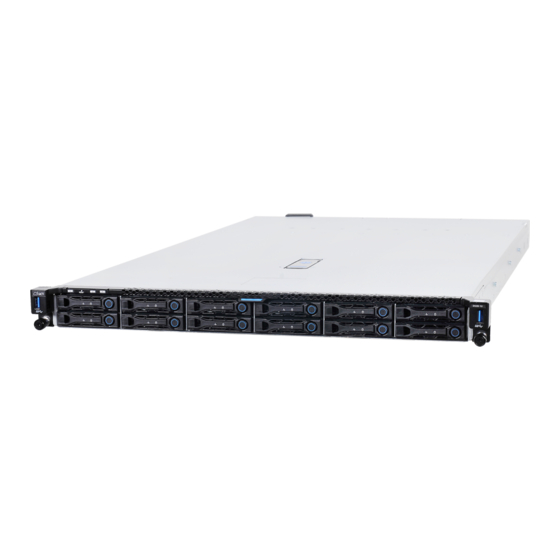
Hitachi Advanced Server HA810 G2
User Guide
This document is for the person who installs, administers, and troubleshoots servers and
storage systems. Hitachi Vantara assumes you are qualified in the servicing of computer
equipment and trained in recognizing hazards in products with hazardous energy levels.
MK-90HAS8024-00
October 2021
Advertisement
Table of Contents

Related Manuals for Hitachi Advanced Server HA810 G2


Summary of Contents for Hitachi Advanced Server HA810 G2
- Page 1 User Guide This document is for the person who installs, administers, and troubleshoots servers and storage systems. Hitachi Vantara assumes you are qualified in the servicing of computer equipment and trained in recognizing hazards in products with hazardous energy levels.
- Page 2 Hitachi, Ltd., or Hitachi Vantara LLC (collectively “Hitachi”. Licensee may make copies of the Materials provided that any such copy is: (i created as an essential step in utilization of the Software as licensed and is used in no other manner;...
- Page 3 Getting help Hitachi Vantara Support Connect is the destination for technical support of products and solutions sold by Hitachi Vantara. To contact technical support, log on to Hitachi Vantara Support Connect for contact information: https://support.hitachivantara.com/en_us/contact-us.html.
-
Page 4: Table Of Contents
Remove the primary PCI riser cage ........................31 Install the primary PCI riser cage ......................... 32 Remove the secondary PCI riser cage ........................ 33 Install the secondary PCI riser cage ........................34 Remove the 8SFF drive backplane ........................35 Hitachi Advanced Server HA810 G2 User Guide... - Page 5 Installing a DIMM ..............................51 Intel Optane persistent memory 200 series ....................... 52 Installing a high-performance fan ......................... 55 Installing an 8SFF display port/USB/optical blank option ..................57 Installing the 4LFF display port/USB option ......................59 Hitachi Advanced Server HA810 G2 User Guide...
- Page 6 Installing and enabling the TPM 2.0 option ....................... 110 Cabling ..........................115 Cabling guidelines ............................. 115 Front I/O cabling ..............................116 Storage cabling ..............................117 SFF cables ................................ 117 LFF cables ................................ 121 Hitachi Advanced Server HA810 G2 User Guide...
- Page 7 Server specifications ............................135 Power supply specifications ..........................136 500 W Flex Slot Platinum Hot-plug Low Halogen Power Supply ................... 136 800 W Flex Slot Platinum Hot-plug Low Halogen Power Supply ................... 137 Hitachi Advanced Server HA810 G2 User Guide...
- Page 8 800 W Flex Slot Universal Hot-plug Low Halogen Power Supply .................. 139 800 W Flex Slot -48 VDC Hot-plug Low Halogen Power Supply ................... 139 1600 W Flex Slot Platinum Hot-plug Low Halogen Power Supply ................. 141 Hitachi Advanced Server HA810 G2 User Guide...
-
Page 9: Component Identification
USB 3.0 port Drive bays Optional 2SFF drive bays The operating system does not recognize this port as a USB port. Item Description Optical drive blank (optional) Serial number/iLO information pull tab Display port (optional) Hitachi Advanced Server HA810 G2 User Guide... -
Page 10: Front Panel Leds And Buttons
Solid green = System on button and system Flashing green = Performing power on sequence power LED1 Solid amber = System in standby Off = No power present Health LED Solid green = Normal Hitachi Advanced Server HA810 G2 User Guide... - Page 11 4 Hz = iLO manual reboot sequence initiated. 8 Hz = iLO manual reboot sequence in progress. Off = Deactivated. NIC status LED Solid green = Link to network. Flashing green = Network active. Off = No network activity. Hitachi Advanced Server HA810 G2 User Guide...
-
Page 12: Uid Button Functionality
The UID button can be used to display the Server Health Summary when the server will not power on. For more information, see the latest iLO 5 User Guide on the Hitachi Vantara Website. Front panel LED power fault codes The following table provides a list of power fault codes, and the subsystems that are affected. -
Page 13: The Systems Insight Display Leds
Off = No link to network Solid green = Network link Flashing green = Network link with activity If power is off, the front panel LED is not active. For status, see Rear panel LEDs Hitachi Advanced Server HA810 G2 User Guide... -
Page 14: Systems Insight Display Combined Led Descriptions
Processor X is not installed in the socket. • Processor X is unsupported. • ROM detects a failed processor during POST. Processor (amber) Amber Green Processor in socket X is in a pre- failure condition. Hitachi Advanced Server HA810 G2 User Guide... - Page 15 • Power supply mismatch at POST or power supply mismatch through hot-plug addition. Power cap (off) Amber Standby Power cap (green) Flashing green Waiting for power Power cap (green) Green Power is available Hitachi Advanced Server HA810 G2 User Guide...
-
Page 16: Rear Panel Components
Slot 2 PCIe4 Slot 3 PCIe4 (optional - requires second processor) Power supply 2 (PS2) Power supply 1 (PS1) (VGA) port OCP 3.0 adapter (if equipped) Serial port (optional) USB 3.0 ports iLO Management Port Hitachi Advanced Server HA810 G2 User Guide... -
Page 17: Rear Panel Leds
Off = One or more of the following conditions exists: • AC power unavailable • Power supply failed • Power supply in standby mode • Power supply exceeded current limit. System board components Hitachi Advanced Server HA810 G2 User Guide... - Page 18 Front display port/USB 2.0 connector Primary (processor 1) PCIe riser connector x4 SATA port 2 x4 SATA port 1 x2 SATA port 3 Front power/USB 3.0 connector SATA optical port 4 x8 NVMe port 2A Hitachi Advanced Server HA810 G2 User Guide...
-
Page 19: Heatsink And Socket Components
Secondary (processor 2) PCIe riser connector Type-a storage controller slot System battery Serial port connector OCP 3.0 adapter bay Heatsink and socket components Item Description Heatsink nuts Alignment screws Latch tabs Heatsink latches Hitachi Advanced Server HA810 G2 User Guide... -
Page 20: System Maintenance Switch Descriptions
3. When the system maintenance switch position 6 is set to the On position and Secure Boot is enabled, some configurations cannot be restored. For more information, see Secure Boot. DIMM slot locations DIMM slots are numbered sequentially (1 through 16) for each processor. Hitachi Advanced Server HA810 G2 User Guide... -
Page 21: Dimm Label Identification
Memory generation PC4 = DDR4 Maximum memory speed 3200 MT/s CAS latency AA = CAS 22-22-22 AA = CAS 26-22-22 (for 3DS LRDIMM) DIMM type R = RDIMM (registered) L = LRDIMM (load reduced) Hitachi Advanced Server HA810 G2 User Guide... -
Page 22: Intel Optane Persistent Memory 200 Series For Label Identification
Serial Number and Part Number Barcode S8089A218040000168APNMAXXXXXXXXXXX Product Name Intel® Optane™ persistent memory Part Number 1234567A Serial Number Barcode 8089-A2-1802-1234567A PBA Number XXXXXX-XXX Drive numbering 8SFF and 8SFF + 2SFF device bay numbering Hitachi Advanced Server HA810 G2 User Guide... -
Page 23: Basic Drive Led Definitions
Basic Drive LED definitions LFF low-profile drive carrier The LFF low-profile drive carrier supports hot-plug SAS and SATA drives. SFF basic drive carrier The SFF basic drive carrier supports hot-plug SAS, SATA, and NVMe drives. Hitachi Advanced Server HA810 G2 User Guide... -
Page 24: Hot-Plug Fans
CAUTION: To avoid damage to the equipment, do not operate the server for extended periods of time if the server does not have the optimal number of fans installed. Although the server might boot, Hitachi Vantara does not recommend operating the server without the required fans installed and operating. - Page 25 CAUTION: A thermal event can damage server components when the Thermal Shutdown feature is disabled in the BIOS/Platform Configuration (RBSU). Hitachi Advanced Server HA810 G2 User Guide...
-
Page 26: Dsc-25 2-Port Sfp28 Card Ports And Leds
A link has not been established Solid green Valid Ethernet link SFP Port 1 Link/Activity LED A link has not been established Solid green Valid Ethernet link Flashing Passing traffic; flashing frequency indicates green traffic intensity Hitachi Advanced Server HA810 G2 User Guide... -
Page 27: Ns204I-P Nvme Os Boot Device Components
Power is up, software has not booted yet Solid green System is up and fully operational NS204i-p NVMe OS Boot Device components Item Description Drive bay 1 Drive bay 2 Thermal interface pad with removable liner M.2 drive retaining latches Hitachi Advanced Server HA810 G2 User Guide... -
Page 28: Ns204I-P Nvme Os Boot Device Led Definitions
If an application stops responding, you can use this method to force a shutdown. • Use a virtual power button selection through iLO . • This method initiates a controlled remote shutdown of applications and the OS before the server enters standby mode. Hitachi Advanced Server HA810 G2 User Guide... -
Page 29: Extend The Server From The Rack
4. Place the server on a sturdy, level surface. Remove the access panel WARNING: To reduce the risk of personal injury from hot surfaces, allow the drives and the internal system components to cool before touching them. Hitachi Advanced Server HA810 G2 User Guide... -
Page 30: Install The Access Panel
Otherwise, the server will shut down gracefully. 2. Do one of the following: Extend the server from the rack. • Remove the server from the rack. • 3. Remove the access panel. Hitachi Advanced Server HA810 G2 User Guide... -
Page 31: Remove The Primary Pci Riser Cage
Disconnect each power cord from the server. 4. Do one of the following: a. Extend the server from the rack. b. Remove the server from the rack. 5. Remove the access panel. Hitachi Advanced Server HA810 G2 User Guide... -
Page 32: Install The Primary Pci Riser Cage
2. Install the access panel. 3. Install the server into the rack. 4. Connect each power cord to the server. 5. Connect each power cord to the power source. 6. Power up the server. Hitachi Advanced Server HA810 G2 User Guide... -
Page 33: Remove The Secondary Pci Riser Cage
6. Remove the access panel. 7. If needed, remove the primary riser cage. 8. Disconnect any cables connected to the riser cage. 9. Remove any expansion boards installed in the riser cage. 10. Remove the riser cage. Hitachi Advanced Server HA810 G2 User Guide... -
Page 34: Install The Secondary Pci Riser Cage
If needed, install expansion boards. Install the access panel. Install the server into the rack. 5. Connect each power cord to the server. 6. Connect each power cord to the power source. Power up the server. Hitachi Advanced Server HA810 G2 User Guide... -
Page 35: Remove The 8Sff Drive Backplane
Removing the hard drive blank CAUTION: To prevent improper cooling and thermal damage, do not operate the server unless all bays are populated with either a component or a blank. Figure 1: Removing an SFF drive blank Hitachi Advanced Server HA810 G2 User Guide... -
Page 36: Removing A Hot-Plug Sas/Sata/Nvme Drive
1. Determine the status of the drive from the hot-plug drive LED definitions. 2. Back up all server data on the drive. 3. Remove the drive. Figure 3: SFF drive Figure 4: LFF drive Hitachi Advanced Server HA810 G2 User Guide... -
Page 37: Releasing The Cable Management Arm
Release the cable management arm and then swing the arm away from the rack. Accessing the Systems Insight Display To access the optional Systems Insight Display: 1. Press and release the panel. 2. After the display ejects, rotate the display to view the LEDs. • 8SF Hitachi Advanced Server HA810 G2 User Guide... - Page 38 • 4LFF Hitachi Advanced Server HA810 G2 User Guide...
-
Page 39: Setup
Hitachi Advanced Server product draws in cool air through the front door and expel warm air through the rear door. Therefore, the front and rear rack doors must be adequately ventilated to allow ambient room air to enter the cabinet, and the rear door must be adequately ventilated to allow the warm air to escape from the cabinet. -
Page 40: Temperature Requirements
NFPA 70, National Electric Code Article 250, as well as any local and regional building codes. In Canada, you must install the equipment in accordance with Canadian Standards Association, Hitachi Advanced Server HA810 G2 User Guide... -
Page 41: Connecting A Dc Power Cable To A Dc Power Source
Because of the high ground-leakage currents associated with multiple servers connected to the same power source, Hitachi Vantara recommends the use of a PDU that is either permanently wired to the building’s branch circuit or includes a nondetachable cord that is wired to an industrial-style plug. NEMA locking-style plugs or those complying with IEC 60309 are considered suitable for this purpose. -
Page 42: Server Warnings And Cautions
Get help to lift and stabilize the product during installation or removal, especially when the product is • not fastened to the rails. Hitachi Vantara recommends that the minimum of two people are required for all rack server installations. If the server is installed higher than chest level, a third person may be required to help align the server. -
Page 43: Rack Warnings
WARNING: When installing a server in a telco rack, be sure that the rack frame is adequately secured at the top and bottom to the building structure. Hitachi Advanced Server HA810 G2 User Guide... -
Page 44: Identifying The Contents Of The Server Shipping Carton
Get help to lift and stabilize the product during installation or removal, especially when the product is not fastened to the rails. Hitachi Vantara recommends that a minimum of two people are required for all rack server installations. A third person may be required to help align the server if the server is installed higher than chest level. -
Page 45: Operating System
For additional system software and firmware updates, download the Service Pack for Hitachi Vantara from the Hitachi Vantara website. Software and firmware must be updated before using the server for the first time, unless any installed software or components require an older version. -
Page 46: Selecting Boot Options
If you do not need to modify the server configuration and are ready to install the system software, press • the F10 key to access Intelligent Provisioning. For more information on automatic configuration, see the UEFI documentation on the Hitachi Vantara website. Registering the server Register the product at https://support.hitachivantara.com/en/user/home.html. -
Page 47: Hardware Options Installation
WARNING: To reduce the risk of personal injury from hot surfaces, allow the power supply or power supply blank to cool before touching it. 4. Insert the power supply into the power supply bay until it clicks into place. 5. Connect the power cord to the power supply. Hitachi Advanced Server HA810 G2 User Guide... -
Page 48: Energy Pack Options
8. Be sure that the power supply LED is green. The installation is complete. Energy pack options Hitachi Vantara offers two backup power options to back up write cache content on the controllers in case of an unplanned server power outage. •... -
Page 49: Installing An Energy Pack
Install the access panel. Install the server in the rack. Connect each power cord to the server. Connect each power cord to the power source. 10. Power up the server. The installation is complete. Hitachi Advanced Server HA810 G2 User Guide... -
Page 50: Memory Options
Disconnect each power cord from the server. 3. Do one of the following: a. Extend the server from the rack. b. Remove the server from the rack. 4. Remove the access panel. 5. Open the DIMM slot latches. Hitachi Advanced Server HA810 G2 User Guide... -
Page 51: Installing A Dimm
Disconnect each power cord from the server. Do one of the following: a. Extend the server from the rack. b. Remove the server from the rack. Remove the access panel. Open the DIMM slot latches. Install the DIMM. Hitachi Advanced Server HA810 G2 User Guide... -
Page 52: Intel Optane Persistent Memory 200 Series
Intel Optane persistent memory 200 series is supported only in servers with second-generation Intel Xeon Scalable processors installed. System requirements for persistent memory module support IMPORTANT: Hitachi Vantara recommends that you implement best-practice configurations such as clustered configurations for high availability (HA). Hitachi Advanced Server HA810 G2 User Guide... - Page 53 Installing persistent memory modules Use this procedure only for new persistent memory module installations. If you are migrating this persistent memory module from another server, see the Persistent Memory User Guide on the Hitachi Vantara website. Prerequisites Before you perform this procedure, make sure that you have the following items available: The components included with the hardware option kit •...
- Page 54 CAUTION: Failure to properly handle persistent memory modules can damage the component and the system board connector. IMPORTANT: Hitachi Vantara recommends that you implement best-practice configurations such as clustered configurations for high availability (HA). 2. Power down the server.
-
Page 55: Installing A High-Performance Fan
RESTful API—Use the iLO RESTful API through tools such as the RESTful Interface Tool (ilorest) or other third-party tools. For more information, see the Intel Optane persistent memory 200 series User Guide on the Hitachi Vantara website. Installing a high-performance fan Certain hardware configurations require high-performance fans. - Page 56 11. Slide the server into the rack. 12. Connect each power cord to the server. 13. Connect each power cord to the power source. 14. Power up the server (Power up the server). Hitachi Advanced Server HA810 G2 User Guide...
-
Page 57: Installing An 8Sff Display Port/Usb/Optical Blank Option
The components included with the hardware option kit T-10 Torx screwdriver • An optical drive, if installing • For more information, contact a Hitachi Vantara authorized reseller. Procedure Back up all server data. Power down the server. Remove all power: a. - Page 58 11. Install the server in the rack. 12. Connect each power cord to the server. 13. Connect each power cord to the power source. 14. Power up the server (Power up the server). Hitachi Advanced Server HA810 G2 User Guide...
-
Page 59: Installing The 4Lff Display Port/Usb Option
Do one of the following: a. Extend the server from the rack. b. Remove the server from the rack. Remove the access panel. Using a Torx T-10 screwdriver, remove the 4LFF display port/USB blank. Hitachi Advanced Server HA810 G2 User Guide... -
Page 60: Drive Options
• The system automatically sets all device numbers. For drive numbering, see Drive bay numbering. • If using only one hard drive, install it in the bay with the lowest device number. • Hitachi Advanced Server HA810 G2 User Guide... -
Page 61: Installing A Hot-Plug Sas, Sata Or Nvme Drive
Procedure 1. Remove the drive blank: LFF drive blank • • SFF drive blank 2. Prepare the drive. LFF drive • • SFF drive Hitachi Advanced Server HA810 G2 User Guide... -
Page 62: Installing The 4Lff Optical Drive Option
T-10 Torx screwdriver • LFF optical cable option kit An optical drive • Procedure Back up all server data. Power down the server. Remove all power: a. Disconnect each power cord from the power source. Hitachi Advanced Server HA810 G2 User Guide... - Page 63 Remove the server from the rack. Remove the access panel. Remove the LFF optical drive bay blank. Install the optical drive. Connect the optical drive cable to the optical drive backplane and to the SATA optical/storage drive connector. Hitachi Advanced Server HA810 G2 User Guide...
-
Page 64: Installing An 8Sff Optical Drive
Installing an 8SFF optical drive Prerequisites Be sure the 8SFF display port/USB/optical blank option is installed. For more information, see Installing an 8SFF display port/USB/optical blank option. Procedure 1. Remove the optical drive blank. Hitachi Advanced Server HA810 G2 User Guide... - Page 65 2. Install the optical drive. 3. Connect the optical drive cable. Hitachi Advanced Server HA810 G2 User Guide...
-
Page 66: Installing A 2Sff Sas/Sata/Nvme Drive Cage
Installing a 2SFF SAS/SATA/NVMe drive cage Prerequisites Universal media bay options are compatible only with the 8SFF Hitachi Vantara recommends installing the P816i-a controller to support 10 SAS/SATA drives. Be sure that you have the following: • The components included with the option kit •... - Page 67 10. Install the access panel. 11. Install the server in the rack. 12. Connect each power cord to the server 13. Connect each power cord to the power source. 14. Power up the server. 15. Install drives. Hitachi Advanced Server HA810 G2 User Guide...
-
Page 68: Primary Pci Riser Cage Options
5. Do one of the following: a. Extend the server from the rack. b. Remove the server from the rack. 6. Remove the access panel. 7. Remove the primary PCI riser cage. 8. Install the expansion board. Hitachi Advanced Server HA810 G2 User Guide... -
Page 69: Installing An Expansion Board In Slot 2
Disconnect each power cord from the server. 5. Do one of the following: a. Extend the server from the rack. b. Remove the server from the rack. 6. Remove the access panel. Hitachi Advanced Server HA810 G2 User Guide... - Page 70 12. Install the access panel. 13. Install the server in the rack. 14. Connect each power cord to the server. 15. Connect each power cord to the power source. 16. Power up the server. Hitachi Advanced Server HA810 G2 User Guide...
-
Page 71: Installing An Optional Primary Pci Riser Board
Remove the server from the rack. Remove the access panel. Remove the primary PCI riser cage. If needed, remove any expansion boards installed in the riser cage. Remove the existing riser board from the PCI riser cage. Hitachi Advanced Server HA810 G2 User Guide... -
Page 72: Installing The Nvme M.2 Riser Option
Disconnect each power cord from the server. Do one of the following: a. Extend the server from the rack. b. Remove the server from the rack. Remove the access panel. Remove the primary PCI riser cage. Hitachi Advanced Server HA810 G2 User Guide... - Page 73 If needed, remove any expansion boards installed in the riser cage. Remove the existing riser board from the riser cage. Install the M.2 riser board. Remove the screw securing the standoff on the riser. 10. Install the M.2 drives. Hitachi Advanced Server HA810 G2 User Guide...
-
Page 74: Installing An Accelerator Or Gpu In The Primary Riser Cage
8. Install the card in the x16 slot in the primary PCI riser cage position. 9. If installing a GPU requiring greater than 75 W, connect the power cable to the primary riser power connector. Hitachi Advanced Server HA810 G2 User Guide... - Page 75 13. Install the server in the rack. 14. Connect each power cord to the server. 15. Connect each power cord to the power source. 16. Power up the server (Power up the server). Hitachi Advanced Server HA810 G2 User Guide...
-
Page 76: Secondary Pci Riser Options
• Remove the access panel. Remove the primary PCI riser cage Remove the primary PCI riser cage. Use a T-10 Torx screwdriver to remove the slot 2 bracket from the primary riser cage. Hitachi Advanced Server HA810 G2 User Guide... - Page 77 If installed, remove the low-profile riser cage. Lift and remove the secondary riser cage latch. Use a T-15 Torx screwdriver to remove the riser cage screw. Hitachi Advanced Server HA810 G2 User Guide...
- Page 78 13. Install the server in the rack. 14. Connect each power cord to the server. 15. Connect each power cord to the power source. 16. Power up the server (Power up the server). Hitachi Advanced Server HA810 G2 User Guide...
-
Page 79: Installing A Secondary Low-Profile Pcie Slot Riser Cage Option
Disconnect each power cord from the server. Do one of the following: a. Extend the server from the rack. b. Remove the server from the rack. Remove the access panel. Install the secondary riser cage. Hitachi Advanced Server HA810 G2 User Guide... -
Page 80: Installing An Expansion Board In The Secondary Riser Cage
CAUTION: To prevent damage to electrical components, properly ground the server before beginning any installation procedure. Improper grounding can cause electrostatic discharge. Back up all server data. Power down the server. Hitachi Advanced Server HA810 G2 User Guide... - Page 81 Disconnect each power cord from the server. Do one of the following: a. Extend the server from the rack. b. Remove the server from the rack. Remove the access panel. Install a secondary riser cage: Low-profile • Full-height • Hitachi Advanced Server HA810 G2 User Guide...
- Page 82 Remove the expansion slot blank: A T-10 Torx screwdriver is required to remove the expansion slot blank. Half-length • • Full-length Hitachi Advanced Server HA810 G2 User Guide...
- Page 83 11. Install the access panel. 12. Install the server in the rack. 13. Connect each power cord to the server.14. 14. Connect each power cord to the power source. Power up the server. Hitachi Advanced Server HA810 G2 User Guide...
-
Page 84: Installing An Accelerator Or Gpu In The Secondary Riser Cage
Disconnect each power cord from the server. Do one of the following: a. Extend the server from the rack. b. Remove the server from the rack. Remove the access panel. If installed, remove the riser cage. Hitachi Advanced Server HA810 G2 User Guide... - Page 85 11. Install the card in the riser cage, and then connect any required cables, if applicable. If installing a GPU requiring greater than 75 W, connect the power cable to the primary riser power connector. Hitachi Advanced Server HA810 G2 User Guide...
-
Page 86: Storage Controller Options
T-15 Torx screwdriver • Procedure 1. Observe the following alerts: WARNING: To reduce the risk of personal injury from hot surfaces, allow the drives and the internal system components to cool before touching them. Hitachi Advanced Server HA810 G2 User Guide... - Page 87 5. Do one of the following: a. Extend the server from the rack. b. Remove the server from the rack. 6. Remove the access panel. 7. Install the controller. 8. Connect the cables. The diagrams below are examples. Hitachi Advanced Server HA810 G2 User Guide...
-
Page 88: Installing A Type-P Storage Controller Option
Installing a type-p storage controller option Prerequisites Before installing this option, be sure you that have the following: The components included with the hardware option kit • T-10 Torx screwdriver • Procedure Observe the following alerts: Hitachi Advanced Server HA810 G2 User Guide... - Page 89 To install a controller in slot 2 of the primary riser: a. Remove the primary PCI riser cage b. Remove the slot 2 blank. c. Using a Torx T-10 screwdriver, install the controller. Hitachi Advanced Server HA810 G2 User Guide...
- Page 90 Install the secondary PCI riser cage. Connect the cables. 8SFF to type-p controller cabling example • • 4LFF to a type-p slot 2 controller cabling example Hitachi Advanced Server HA810 G2 User Guide...
- Page 91 10. Install the access panel. 11. Install the server in the rack. 12. Connect each power cord to the server. 13. Connect each power cord to the power source. 14. Power up the server. Hitachi Advanced Server HA810 G2 User Guide...
-
Page 92: Processor And Heatsink Options
7. If installing processors over 150W, install high performance fans. 8. Install the processor heatsink assembly: a. Remove the dust cover from the socket. b. Identify the front of server label on the heatsink. Hitachi Advanced Server HA810 G2 User Guide... - Page 93 Using a T-30 Torx screwdriver, tighten the nuts. NOTE: Do not tighten the nuts more than 12 in-lbs. or 1.3Nm. Overtightening could crack or damage the nuts. The installation is complete. Hitachi Advanced Server HA810 G2 User Guide...
-
Page 94: Installing A High Performance Heatsink
Remove the server from the rack. Remove the access panel. Observe the following cautions. CAUTION: Be sure to loosen each heatsink nut in the order indicated. Otherwise, damage might occur to the heatsink or processor. Hitachi Advanced Server HA810 G2 User Guide... - Page 95 Turn the processor heatsink assembly over and place it on a work surface with the processor assembly facing up. Release the processor from the heatsink: Be sure to unlatch all corners of the processor carrier. The processor remains attached to the carrier. Hitachi Advanced Server HA810 G2 User Guide...
- Page 96 Identify the front of server label on the heatsink. Align the assembly with the alignment posts and gently lower it down until it sits on the socket. The processor heatsink assembly will only install one way. Hitachi Advanced Server HA810 G2 User Guide...
-
Page 97: Installing The Systems Insight Display Power Module
The installation is complete. Installing the Systems Insight Display power module Prerequisites Before installing this option, be sure you have the following: • The components included with the hardware option kit • T-10 Torx screwdriver Procedure Hitachi Advanced Server HA810 G2 User Guide... - Page 98 Do one of the following: a. Extend the server from the rack. b. Remove the server from the rack. Remove the access panel Remove the access panel. Disconnect the cable from the system board. Hitachi Advanced Server HA810 G2 User Guide...
- Page 99 Guide the SID cable through the front of the server. 10. Install the SID module into the front panel. Using a T-10 Torx screwdriver, secure the module to the chassis with the screws from the kit. • 8 SFF Hitachi Advanced Server HA810 G2 User Guide...
- Page 100 • 4 LFF 11. Connect the cable. Hitachi Advanced Server HA810 G2 User Guide...
-
Page 101: Installing An Ocp 3.0 Adapter Card
Extend the server from the rack. • Remove the server from the rack. • Remove the access panel. Remove the rear wall blank or riser. Remove the OCP 3.0 adapter blank. Install the OCP 3.0 adapter Hitachi Advanced Server HA810 G2 User Guide... -
Page 102: Installing The Serial Cable Option
Power down the server. Remove all power: a. Disconnect each power cord from the power source. b. Disconnect each power cord from the server. Do one of the following: a. Extend the server from the rack. Hitachi Advanced Server HA810 G2 User Guide... -
Page 103: Installing The Chassis Intrusion Detection Switch Option
Power down the server. Remove all power: a. Disconnect each power cord from the power source. b. Disconnect each power cord from the server. Do one of the following: a. Extend the server from the rack. Hitachi Advanced Server HA810 G2 User Guide... -
Page 104: Installing The Dsp Dsc-25 Sfp28 Card
To prevent damage, observe antistatic precautions. CAUTION: To prevent improper cooling and thermal damage, do not operate the server unless all PCI slots have either an expansion slot cover or an expansion board installed. Hitachi Advanced Server HA810 G2 User Guide... - Page 105 5. Remove the server from the rack. 6. Remove the primary PCIe riser cage. 7. Remove the PCIe blank from slot 1 on the primary riser cage. 8. Install the DSC-25 card into the PCIe slot. Hitachi Advanced Server HA810 G2 User Guide...
- Page 106 10. Install the server in the rack. 11. Connect each power cord to the server. 12. Connect each power cord to the power source. 13. Power up the server. The installation is complete. Hitachi Advanced Server HA810 G2 User Guide...
-
Page 107: Installing The Ns204I-P G2 Boot Device Option
Remove the liner from the thermal interface pad. Install the drives. Installing the boot device Power down the server. Remove all power: a. Disconnect each power cord from the power source. b. Disconnect each power cord from the server. Hitachi Advanced Server HA810 G2 User Guide... -
Page 108: Trusted Platform Module 2.0 Option
Install the TPM 2.0 with specific operating system support such as Microsoft Windows Server 2012 R2 and later. For more information about operating system support, see Hitachi Vantara website. (For more information about Microsoft Windows BitLocker Drive Encryption feature, see the Microsoft website https://www.microsoft.com... -
Page 109: Trusted Platform Module 2.0 Guidelines
For any compliance issues arising from your operation/usage of TPM which violates the above mentioned requirement, you shall bear all the liabilities wholly and solely. Hitachi Vantara will not be responsible for any related liabilities. -
Page 110: Installing And Enabling The Tpm 2.0 Option
WARNING: To reduce the risk of personal injury from hot surfaces, allow the drives and the internal system components to cool before touching them. Update the system ROM. Locate and download the latest ROM version from Hitachi Vantara website. Follow the instructions on the website to update the system ROM. Power down the server. - Page 111 Line up the tabs on the cover with the openings on either side of the TPM connector. b. To snap the cover into place, firmly press straight down on the middle of the cover. Hitachi Advanced Server HA810 G2 User Guide...
- Page 112 In UEFI Boot Mode, the Trusted Platform Module can be configured to operate as TPM 2.0 (default) or • TPM 1.2. In Legacy Boot Mode, the Trusted Platform Module configuration can be changed between TPM 1.2 and • TPM 2.0 (default), but only TPM 1.2 operation is supported. Hitachi Advanced Server HA810 G2 User Guide...
- Page 113 5. Press the F10 key to save your selection. 6. When prompted to save the change in System Utilities, do one of the following: If in graphical mode, click Yes. • If in text mode, press the Y key. • Hitachi Advanced Server HA810 G2 User Guide...
- Page 114 • Always store the recovery key/password in multiple locations. • Always store copies of the recovery key/password away from the server. Do not save the recovery key/password on the encrypted hard drive. • Hitachi Advanced Server HA810 G2 User Guide...
-
Page 115: Cabling
If a cable does not disconnect easily, check for any release latch that must be pressed to disconnect • the cable. Hitachi Advanced Server HA810 G2 User Guide... -
Page 116: Front I/O Cabling
Front I/O cabling LFF Optical Disk Drive cabling SFF Optical Disk Drive cabling LFF front display port/USB cabling Hitachi Advanced Server HA810 G2 User Guide... -
Page 117: Storage Cabling
P20816-001 8SFF SAS/SATA backplane Embedded SATA ports 1/2 P20817-001 2SFF SAS/SATA backplane Type-a controller P26551-001 2SFF SAS/SATA backplane Type-p controller P20855-001 Direct attach NVMe cable kit 8SFF NVMe backplane Embedded NVMe ports 1B/2B Hitachi Advanced Server HA810 G2 User Guide... - Page 118 Type-p MR controller P26553-001 8SFF Tri-mode backplane Type-a SR controller P20847-001 Embedded Slimline Connector Type-a or Type-p controller OCP x16 enablement kit 8SFF x1 Tri-Mode U.3 backplane + 2SFF NVMe backplane to type-p Tri-Mode controller Hitachi Advanced Server HA810 G2 User Guide...
- Page 119 8SFF x4 + 2SFF backplanes to type-p controller 8SFF x4 + 2SFF backplanes to type-a and type-p controllers 2SFF x4 backplane to primary NVMe riser Hitachi Advanced Server HA810 G2 User Guide...
- Page 120 8SFF x1 Tri-Mode U.3 backplane to type-p controller on slot 2 8SFF SAS/SATA backplane to system board and 2-port type-a controller 8SFF x4 backplane to 2-port type-p controller Hitachi Advanced Server HA810 G2 User Guide...
-
Page 121: Lff Cables
8SFF x4 backplane direct attach 8SFF SAS/SATA backplane to embedded SATA LFF cables Option kit Cable part number Connects from Connects to LFF Internal Cable Kit P20808-001 4LFF SAS/SATA Embedded SATA port 2 Hitachi Advanced Server HA810 G2 User Guide... - Page 122 4LFF backplane to controllers 4LFF to embedded SAS/SATA 4LFF to type-a controller 4LFF to type-p controller Hitachi Advanced Server HA810 G2 User Guide...
-
Page 123: Software And Configuration Utilities
The Active Health System does not collect information about your operations, finances, customers, employees, or partners. Examples of information that is collected: Server model and serial number • Processor model and speed • Hitachi Advanced Server HA810 G2 User Guide... -
Page 124: Ilo 5
It takes less than 5 minutes to download the Active Health System Log and send it to a support professional to help you resolve an issue. When you download and send Active Health System data to Hitachi Vantara, you agree to have the data used for analysis, technical resolution, and quality improvements. The data that is collected is managed according to the privacy statement, available at https://www.hitachivantara.com/en-... -
Page 125: Ilo Service Port
◦ iLO RESTful API ◦ Hitachi Vantara recommends the USB to Ethernet Adapter (part number Q7Y55A). Hitachi Vantara recommends the Micro USB to USB Adapter (part number 789904-B21). When you use the iLO Service Port: Actions are logged in the iLO event log. -
Page 126: Restful Interface Tool
OS software. Intelligent Provisioning also prepares the system to integrate optimized server support software from the Service Pack for Hitachi Vantara (SPV). SPV is a comprehensive systems software and firmware solution for Advanced Server, their enclosures. These components are preloaded with a basic set of firmware and OS components that are installed along with Intelligent Provisioning. -
Page 127: Uefi System Utilities
2. Select a setting. UEFI Mode (default)—Configures the system to boot to a UEFI • compatible operating system. • Legacy BIOS Mode—Configures the system to boot to a traditional operating system in Legacy BIOS compatibility mode. Hitachi Advanced Server HA810 G2 User Guide... -
Page 128: Secure Boot
2. Press any key to acknowledge that you are physically present. This step ensures that certain features, such as disabling Secure Boot or managing the Secure Boot certificates using third-party UEFI tools, are not restricted. Hitachi Advanced Server HA810 G2 User Guide... -
Page 129: Smart Storage Administrator
Accessing SSA in the offline environment IMPORTANT: If you are updating an existing server in an offline environment, obtain the latest version of SSA through Service Pack for Hitachi Vantara before performing configuration procedures. Using one of multiple methods, you can run SSA before launching the host operating system. In offline mode, users can configure or maintain detected and supported devices, such as optional smart array controllers and integrated smart array controllers. -
Page 130: Usb Support
USB support Hitachi Vantara G2 server supports all USB operating speeds depending on the device that is connected to the server. External USB functionality Hitachi Vantara provides external USB support to enable local connection of USB devices for server administration, configuration, and diagnostic procedures. - Page 131 4. Launch the System Utilities and select Embedded Applications > Firmware Update. 5. Select a device. The Firmware Updates screen lists details about your selected device, including the current firmware version in use. 6. Select Firmware File. Hitachi Advanced Server HA810 G2 User Guide...
-
Page 132: Drivers
Drivers IMPORTANT: Always perform a backup before installing or updating device drivers. Update drivers using any of the Following: • Download the latest Service Pack for Hitachi Vantara (includes smart update manager) • Download smart update manager for Linux •... -
Page 133: Software And Firmware
Error Message Guide for Hitachi Advanced Server HA800 G2 servers provide a list of error messages and information to assist with interpreting and resolving error messages. To access troubleshooting resources for your product, see the Hitachi Vantara Website. Hitachi Advanced Server HA810 G2 User Guide... -
Page 134: Removing And Replacing The System Battery
Remove the server from the rack. 4. Remove the access panel. 5. System board components. 6. Remove the battery. 7. To replace the component, reverse the removal procedure. 8. Properly dispose of the old battery. Hitachi Advanced Server HA810 G2 User Guide... -
Page 135: Specifications
410 ft) above 900 m (2953 ft) to a maximum of 3048 m (10,000 ft). For information about approved hardware configurations, contact customer support. Server specifications Specification Value Height 4.28 cm (1.68 in) Depth, SFF 74.19 cm (29.21 in) Hitachi Advanced Server HA810 G2 User Guide... -
Page 136: Power Supply Specifications
2.7 A at 200 VAC 2.3 A at 240 VDC for China only Maximum rated input power 557 W at 100 VAC 539 W at 200 VAC 537 W at 240 VDC for China only Hitachi Advanced Server HA810 G2 User Guide... -
Page 137: 800 W Flex Slot Platinum Hot-Plug Low Halogen Power Supply
Power supply output — Rated steady-state power 800 W at 100 VAC to 127 VAC input 800 W at 100 VAC to 240 VAC input 800 W at 240 VDC input for China only Hitachi Advanced Server HA810 G2 User Guide... -
Page 138: 800 W Flex Slot Titanium Hot-Plug Low Halogen Power Supply
800 W at 200 VAC to 240 VAC input 800 W at 240 VDC input for China only Maximum peak power 800 W at 200 VAC to 240 VAC input 800 W at 240 VDC input for China only Hitachi Advanced Server HA810 G2 User Guide... -
Page 139: 800 W Flex Slot Universal Hot-Plug Low Halogen Power Supply
Rated input voltage -40 VDC to -72 VDC -48 VDC nominal input Rated input current 22.1 A at -40 VDC input 18.2 A at -48 VDC input, nominal input 12.0 A at -72 VDC input Hitachi Advanced Server HA810 G2 User Guide... - Page 140 The DC supply source is to be located within the same premises as the equipment. • Switching or disconnecting devices must not be in the earthed circuit conductor between the DC source and the point of connection of the earthing electrode conductor. Hitachi Advanced Server HA810 G2 User Guide...
-
Page 141: 1600 W Flex Slot Platinum Hot-Plug Low Halogen Power Supply
Rated steady-state power 1600 W at 200 VAC to 240 VAC input 1600 W at 240 VDC input Maximum peak power 2200 W for 1 ms (turbo mode) at 200 VAC to 240 VAC input Hitachi Advanced Server HA810 G2 User Guide... - Page 142 Hitachi Vantara Corporate Headquarters Contact Information 2535 Augustine Drive USA: 1-800-446-0744 Santa Clara, CA 95054 USA Global: 1-858-547-4526 HitachiVantara.com | community.HitachiVantara.com HitachiVantara.com/contact...