Table of Contents
Advertisement
Quick Links
Advertisement
Table of Contents

Related Manuals for Panasonic HD-PLC DA-PU100


Summary of Contents for Panasonic HD-PLC DA-PU100
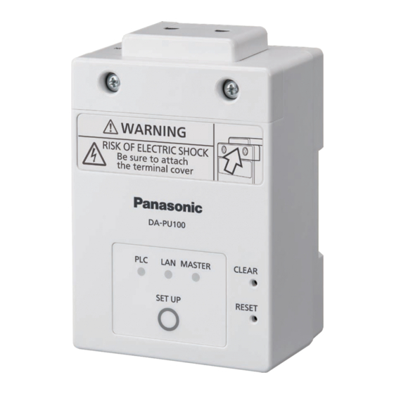
- Page 1 Administrator's Manual PLC Adaptor Model No. DA-PU100...
-
Page 2: Table Of Contents
DA-PU100 Series Administrator's Manual Table of Contents 1 Introduction ..............................5 1.1 Product appearance......................... 5 1.2 Supplied items ..........................5 1.3 Available tools ..........................6 1.4 Names and Functions of Parts ......................7 2 Installation and operation ........................10 2.1 Installation and operation flow ....................... 10 2.2 Determine installation location and number of HD-PLC adaptors .......... - Page 3 DA-PU100 Series Administrator's Manual 5 Troubleshooting ............................ 59 When it seems has a problem ........................ 59 About communication speed ........................60 About the influence on other electric appliances ..................61 About the Internet ........................... 61 Others ..............................61 Factory Reset............................61 6 Specifications ............................
- Page 4 DA-PU100 Series Administrator's Manual Chapter 1 Introduction...
-
Page 5: Introduction
DA-PU100 Series Administrator's Manual 1 Introduction 1.1 Product appearance 1.2 Supplied items Check that all accessories are included before installing the product. PLCAdaptor (1) Fixing brackets (3) Small fixing screws (3) Large fixing screws (3) Operating Manual (1) -
Page 6: Available Tools
DA-PU100 Series Administrator's Manual 1.3 Available tools The following three tools are available to support efficient work during new installation, maintenance, and operation monitoring of the PLC adaptor. Tool When Abstract Setting Tool New installation Performs parameter settings of multiple PLC adaptors in batch during initial installation. -
Page 7: Names And Functions Of Parts
DA-PU100 Series Administrator's Manual 1.4 Names and Functions of Parts Unit With the terminal cover removed ① MASTER indicator: Indicates whether the product is a MASTER or TERMINAL. ② LAN indicator: Indicates the status of the LAN connection. ③ PLC indicator: Indicates the status of the PLC link. ④... - Page 8 DA-PU100 Series Administrator's Manual The state of each indicator MASTER indicator On (green) *1 Operating as PRIMARY MASTER. On (orange) *1 Operating as SECONDARY MASTER. Operating as TERMINAL. LAN indicator Blinking Connected to the LAN. PLC indicator On (green) *1 Connected to a PLC device.
- Page 9 DA-PU100 Series Administrator's Manual Chapter 2 Installation Operation...
-
Page 10: Installation And Operation
DA-PU100 Series Administrator's Manual 2 Installation and operation 2.1 Installation and operation flow Determine Installation Parameter Installation Confirmation Operation Wiring settings location Installation Manual Administrator's Manual 2.2 Determine installation location and number of HD-PLC adaptors Determine the installation location of the PLC adaptor from the wiring system diagram etc. Determine the location and the number of PLC adaptors to be installed. - Page 11 DA-PU100 Series Administrator's Manual Specific example of parameter setting What to prepare PLC adaptor to set up Power connection cable etc. PC for setting (pre-installed setting tool) DHCP server (substitutable for TA and router) DHCP server configuration example IP address 192.168.0.1 Subnet mask 255.255.255.0 * 1 Adhesive label for device name (After setting, label is pasted on the main unit)
- Page 12 DA-PU100 Series Administrator's Manual Connection environment during setting work AC 100-240 V PC for setup tool HD-PLC Adaptor DHCP Server *2 LAN HUB Setting parameters ① Connect the PLC adaptor to the power supply. Start (e.g. Every 8 to 10 units) ②...
- Page 13 DA-PU100 Series Administrator's Manual Examples of creating configuration parameters Make the settings according to the network environment and security requirements by the following procedure. ①Save CSV file ②Enter setting values in CSV file ③Enter Parameters with the Setting Tool Save CSV file Launch HD-PLC Setting Tool and display the following screen.
- Page 14 DA-PU100 Series Administrator's Manual Enter the contents of the IPv4 tab of Setting Tool. DHCP, Auto IP Mode, IP Address, Subnet Mask, and Default Gateway: Set respectively Enter the contents of the IPv6 tab of the Setting Tool. (Only when setting is necessary) IPv6 Protocol, IPv6 Auto Configuration SW, IPv6 IP Address, Default router, Link local address, and Auto configuration: Set respectively...
-
Page 15: Turn On The Power
DA-PU100 Series Administrator's Manual 2.3.1 Turn on the power The PLC indicator lights orange for 5 to 10 seconds after turning on the power. • After that, it glows green when linking with another PLC adaptor. When connected to a network device, the LAN indicator lights up or blinks. •... -
Page 16: Rs-485 Setting
DA-PU100 Series Administrator's Manual 2.3.2 RS-485 setting RS-485 setting is done with the Setting Tool. Please set the parameters of the PLC adaptor according to the RS - 485 equipment parameters. The maximum number of units that can be connected is 31 units. (1) Master / Slave switching Please select Master and Slave. -
Page 17: Usb Setting
DA-PU100 Series Administrator's Manual 2.3.3 USB setting PLC Adapor setting For the PLC adaptor using USB, please enable the USB function with the Setup tool. • Please connect the USB device and the PLC adaptor with a USB cable. • •... -
Page 18: About Security
DA-PU100 Series Administrator's Manual 2.3.4 About security In order to prevent invasion of third parties into the network, the security measures provided • by this product are as follows. Only the terminal adaptors registered with the same shared key as the master adaptor ... -
Page 19: Install And Wiring This Product
DA-PU100 Series Administrator's Manual 2.4 Install and Wiring this product 2.4.1 Installation of PLC adaptor (implementation) Install individual PLC adaptors to the determined construction site. • When installing to the place sequentially from the master, you can install it while confirming the •... -
Page 20: Connection Of Power Supply
DA-PU100 Series Administrator's Manual 2.4.2 Connection of power supply Follow this procedure to wire the product to the distribution box. 1. Remove the terminal cover. • Use a Phillips screwdriver to remove the terminal cover fixing screw. 2. Wire L phase of the power line to terminal L(①) and N phase to terminal N(②). Connect the L phase terminal (①) and N phase terminal (②) correctly. -
Page 21: Connection Of Network Equipment
DA-PU100 Series Administrator's Manual 2.4.3 Connection of network equipment 1. Connect the LAN cable (CAT 5 or more) to the LAN connector of the PLC adaptor and connect the network equipment to be used to the LAN cable. LAN cable Notice This product does not have a router function. -
Page 22: Connection Of Rs-485 Equipment
DA-PU100 Series Administrator's Manual 2.4.5 Connection of RS-485 equipment RS-485 cable wiring PIN No. Signal name A (Driver Out/Receiver In) B (Inverted Driver Out/Inverted receiver In) A (Driver Out/Receiver In) B (Inverted Driver Out/Inverted receiver In) SG (Signal Ground) 1-pin 5-pin RS-485 Terminal(attached)... -
Page 23: Confirmation
DA-PU100 Series Administrator's Manual 2.5 Confirmation Confirm that installed PLC adaptor is working correctly. What to prepare Installed PLC adaptor PC for the Confirmation tool (Maintanace tool previously installed) AC 100-240 V PC for Confirmation tool Installed PLC Adaptor LAN HUB (1) Connect the PC to the same LAN network as the PLC adaptor. -
Page 24: Operation
DA-PU100 Series Administrator's Manual 2.6 Operation Monitor the communication status of installed PLC adaptors. What to prepare Installed PLC adaptor PC for Operating tool (Monitoring Tool previously installed) AC 100-240 V PC for Operation tool Installed PLC Adaptor LAN HUB (1) Connect the PC to the same LAN network as the PLC adaptor. - Page 25 DA-PU100 Series Administrator's Manual Chapter 3 PC Tools...
-
Page 26: Pc Tools
It is possible to output the status of the PLC adaptor as a log. (Setting Tool) (Maintenance Tool) (Monitoring Tool) PC Tools can be downloaded from the following URL. For details, refer to the manual of each PC tool. https://panasonic.net/cns/pcc/support/plc/index.html... -
Page 27: Setting Tool
DA-PU100 Series Administrator's Manual 3.1 Setting Tool By setting multiple PLC adaptors collectively, you can perform the setting work efficiently. Based on the setting data created in Excel etc. beforehand, it supports writing to one unit and writing to multiple units in operation. The screen configuration of the HD-PLC setting tool is described below. -
Page 28: Maintenance Tool
DA-PU100 Series Administrator's Manual 3.2 Maintenance Tool A list of PLC adaptors on the network can be created and displayed in list format and logical topology format. You can also update the firmware for the selected PLC adaptor. 3.2.1 List format display In the list format screen, you can check the master / terminal distinction, device name, IP address, MAC address, firmware version, and PLC adaptor status. -
Page 29: Logical Topology Format Display
DA-PU100 Series Administrator's Manual 3.2.2 Logical topology format display On the Logical Topology Format screen, the Master / Terminal distinction is displayed as an icon. The connection relationship (logical topology) of each PLC adaptor is displayed with icons and lines. Since the color of the line changes with the connection speed, you can understand at a glance the connection point where the speed is slow. -
Page 30: Monitoring Tool
DA-PU100 Series Administrator's Manual 3.3 Monitoring Tool It periodically monitors the PHY rate of the PLC adaptor in the range specified by the IP address, and it is possible to notify the administrator of the abnormality when it falls below the set value. 3.3.1 Setting up the monitoring tool (1)... -
Page 31: Status Indication Of Task Tray
DA-PU100 Series Administrator's Manual (8) Check box for balloon notification available ・ Available balloon notification when the communication speed drops below the lower limit. (9) Check box for e-mail sending ・ Sets available sending e-mail with balloon notification (10) Text box for e-mail send address ・... - Page 32 DA-PU100 Series Administrator's Manual Chapter 4 Preparation Operation...
-
Page 33: Preparation For Operation
DA-PU100 Series Administrator's Manual 4 Preparation for operation About the network Functions using the PLC network as a communication medium include an Ethernet Bridge that performs Ethernet communication, a Serial Bridge that performs serial communication, and a USB Bridge that performs USB communication. 4.1 PLC Network The HD-PLC network is a network in which communication data is superimposed on power lines. -
Page 34: Tips For Stable Use
DA-PU100 Series Administrator's Manual 4.1.2 Tips for stable use In order to use the PLC network stably, it is important to reduce the signal level attenuation of the power line communication and reduce the noise level. 4.1.2.1 Signal attenuation due to transmission line resistance Cause: Long transmission path length High impedance of the wire used... -
Page 35: Noise In Transmission Line
DA-PU100 Series Administrator's Manual 4.1.2.2 Noise in transmission line Cause: · Noise from other equipment on the transmission line (inverter, motor, and AC adaptor, etc.) · Influence of external noise (broadcast wave, radio communication wave, etc.) Corrective action example: · Remove noise source from transmission line and keep it away. ·... -
Page 36: Influence Of Signal Attenuation And Reflection Due To Branching Of The Transmission Line
DA-PU100 Series Administrator's Manual 4.1.2.3 Influence of signal attenuation and reflection due to branching of the transmission line Cause: · Many wiring branches (distribution board, joint box, etc.) Corrective action example: · Review the HD-PLC position for less signal attenuation. ·... -
Page 37: Guidelines For Placing Plc Adaptors
DA-PU100 Series Administrator's Manual 4.1.3 Guidelines for placing PLC adaptors When installing the HD-PLC in the main power line of a building / condominium, put a Master at the part that collects data (which distribution board point etc.), and set up a Terminal at each residence or on the distribution board. - Page 38 DA-PU100 Series Administrator's Manual In addition, since the PLC uses the power line, it is necessary to match the phases of L1 and L2 so that it can communicate using the same line on the 100 V line. If the phases are different, PLC communication will be performed using different lines, which may cause the PLC signal to attenuate, slow the communication speed, or cause communication to become impossible.
- Page 39 DA-PU100 Series Administrator's Manual Placement example Approx. 100m Approx. Approx. Distribution Approx. 50m board Distribution board (Aisle) Monitor Total power line Approx. 250 m Hopping 7hops Connection diagram Camera Master ④ Terminal ③ Terminal ② Terminal ① Terminal ⑤ Terminal ⑥ Terminal ⑦...
-
Page 40: What To Do If Plc Communication Is Not Possible
DA-PU100 Series Administrator's Manual 4.1.4 What to do if PLC communication is not possible In case of outlet installation, install a noise filter in the noise equipment The outlet side should be connected directly to the wall outlet. Moreover, if you connect to one port of the PLC wall outlet, connect a power strip with a noise filter to the other, and connect other equipment to the power strip, you can make PLC performance more enriched. - Page 41 DA-PU100 Series Administrator's Manual When there is another distribution board between PLCs These are examples using Japanese power line and distribution board. If another distribution board (distribution board B) exists on the path between PLCs, if PLC 1 and PLC 2 cannot communicate (PLC link is not made), install PLC 3 on distribution board B. You can communicate by hopping with PLC 1 →...
- Page 42 DA-PU100 Series Administrator's Manual When noise equipment is connected to distribution board These are examples using Japanese power line and distribution board. If PLC 1 and PLC 2 can not communicate (influence PLC link) due to the influence of noise equipment connected to distribution board B, installing (inserting) a noise filter in the sub breaker to which the noise equipment is connected will often cause noise to decrease, and you can communicate.
- Page 43 DA-PU100 Series Administrator's Manual About breakers There are two kinds of AC breakers, which affect PLC communication. (1) Thermal-operated breaker There is no particular attenuation factor. If it is a breaker in a distribution board for general households, there will be no problems. (2) Fully electromagnetic breaker When the current capacity is 10 A or less, the electromagnetic coil wire is thin and the L value is increased by rolling a lot of wires to increase the magnetic force.
-
Page 44: Ip Network
DA-PU100 Series Administrator's Manual 4.2 IP network This PLC adaptor is managed by an IP address. Access to the PLC adaptor can be accessed by specifying an IP address from a PC that exceeds the router for alive monitoring and setting of the PLC adaptor. 4.2.1 MAC(Media Access Control) Address It is a 6-byte address which has no duplicate around the world. -
Page 45: Subnet Mask
DA-PU100 Series Administrator's Manual 4.2.3 Subnet Mask Subnet is a 32-bit address that indicates how many bits in the address are used as network IDs Network address AND process Class B Subnet outline Because of network management purpose and special purpose, the following addresses cannot be set. -
Page 46: Internet Protocol
DA-PU100 Series Administrator's Manual 4.2.4 Internet Protocol IP (Internet Protocol) is defined as the 3 layer in the OSI reference model and controls packet transmission and reception. Typical roles are as follows: IP address identification Fragmentation (decomposition) of IP datagram and combining Selection of the route by IP address IP datagram Term... -
Page 47: Hd-Plc Multi-Hop
DA-PU100 Series Administrator's Manual 4.3 HD-PLC Multi-hop The HD-PLC network consists of a Master that manages the entire network and other Terminals. The terminal authenticates with the Master using the authentication key when joining the HD-PLC network. Therefore, please set all the same authentication keys for HD-PLC making up HD-PLC network. 1. - Page 48 DA-PU100 Series Administrator's Manual 5. Multi-hop In the conventional HD-PLC, two PLC terminals were to communicate directly. On the other hand, the multi-hop technology of the HD-PLC can expand the range of the communication area by having a relay function among the nodes. As shown below, even when communication cannot be directly performed, by using multi-hopping, communication can be performed by relaying other terminals.
- Page 49 DA-PU100 Series Administrator's Manual No multi-hop connection example Multi-hop connection example Resolve weak points with multi-hop communication PLC The weak points of the conventional "HD-PLC" topology · Even if communication cannot be made directly, it is resolved by installing a relay node ·...
- Page 50 DA-PU100 Series Administrator's Manual 6. Ethernet bridge function The Ethernet bridge function connects Ethernet devices by power line communication. By using two or more PLC adaptors it extends Ethernet communication via power line. Ethernet bridge connection example Power Line: PLCnet1 (Network address2) Ethernet1 Ethernet3 (Network address1)
-
Page 51: Rs-485 Network
DA-PU100 Series Administrator's Manual 4.4 RS-485 network The RS-485 network uses differential signals and is therefore a relatively inexpensive network capable of long-distance high-speed communication. A 2-wire type is often used for the wiring. The maximum line length is 1,200 m, and the maximum communication speed decreases according to the distance. -
Page 52: Relationship Between Replacement Part Of Rs-485 Cable And Hd-Plc Connection
DA-PU100 Series Administrator's Manual 4.4.1 Relationship between replacement part of RS-485 cable and HD-PLC connection By replacing the RS-485 network with power line communication using the PLC adaptor, it is possible to reduce the length of the RS-485 cable. RS-485 equip Controller RS-485 equip RS-485 equip... -
Page 53: Rs-485 Master Settings
DA-PU100 Series Administrator's Manual 4.4.2 RS-485 Master settings When RS-485 is connected, set Master separately from HD-PLC setting. It is recommended that the same PLC adaptor be used for RS-485 Master and HD-PLC Master. Masters are the same case Mode: Master Mode: Slave Slave IP Address: Master IP Address:... -
Page 54: Transfer Of Rs-485 Data Among Hd-Plcs
DA-PU100 Series Administrator's Manual 4.4.3 Transfer of RS-485 data among HD-PLCs 4.4.3.1 When 485-Master is connected to PLC-Master · Maximum performance can be obtained when 485-Master is connected to PLC-Master. · From the PLC, to which 485-Master is connected, transfer the command by unicast to each PLC-Terminal which 485-Slave is connected. -
Page 55: When 485-Master Is Connected To Plc-Terminal
DA-PU100 Series Administrator's Manual 4.4.3.2 When 485-Master is connected to PLC-Terminal · Since the connection destination of the 485-Master is arbitrary, it can also be connected to a PLC-Terminal However, the performance is lower than when connected to a PLC-Master. ·... -
Page 56: Command Response Time When Using Hd-Plc
DA-PU100 Series Administrator's Manual 4.4.4 Command response time when using HD-PLC Transfer of RS-485 frame by HD-PLC is performed as shown in the timing chart below. Command response time 485-Master 485 Trans- time Transfers Inter PLC MHP Trans- time Transfers 485-Slave 485 Trans- time Transfers... -
Page 57: Usb Network
DA-PU100 Series Administrator's Manual 4.5 USB Network Using the PLC adaptor, you can connect various devices with USB ports to the PLC network. With the USB virtual extension cable, you can use multiple USB devices. USB cable Up to 5 m (USB 2.0 standard) PLC Adaptor Up to 2000 m (10 hops, depending on the environment) •... - Page 58 DA-PU100 Series Administrator's Manual Chapter 5 Troubleshooting...
-
Page 59: Troubleshooting
DA-PU100 Series Administrator's Manual 5 Troubleshooting When it seems has a problem Symptom Possible Cause Remedy Power is not connected. Connect a power source. None of the indicators light or blink. The product might be malfunctioning. If the PLC indicator does not light, contact your dealer. -
Page 60: About Communication Speed
DA-PU100 Series Administrator's Manual About communication speed Symptom Possible Cause Remedy Communication Using a noise filtered or When using the power strip, please use without a noise speed is slow, or lightning surge power strip. filter, or lightning surge. communication is interrupted. -
Page 61: About The Influence On Other Electric Appliances
DA-PU100 Series Administrator's Manual About the influence on other electric appliances Symptom Possible Cause Remedy Noises entering the This product may affect shortwave Please connect these electric shortwave radio / radio, lighting fixtures with a dimming appliances to another outlet or use as lighting fixtures with a function and touch lamps. - Page 62 DA-PU100 Series Administrator's Manual Chapter 6 Specifications...
-
Page 63: Specifications
DA-PU100 Series Administrator's Manual 6 Specifications 6.1 Unit Temperature : -25℃ – 60℃ Operating environment Humidity : 20% RH – 85% RH (No condensation) Degree of protection from solid IP5X objects External dimensions Width x Height x Depth (Approx.): 75 mm x 102 mm x 47 mm (2.95 in. x 4.02 in. x 1.85 in.) (Unit only. -
Page 64: Ethernet Port
DA-PU100 Series Administrator's Manual 6.3 Ethernet port Physical interface IEEE802.3 (10BASE-T) / IEEE802.3u (100BASE-TX) Auto MDI/MDI-X / Auto negotiation Protocol TCP/IP (IPv4/IPv6) Access method CSMA/CD Number of connection devices Max. 8 devices per Master or Terminal adaptor *1 *1.This is the recommended number when using a switching hub. 6.4 RS-485 port Standard EIA-485... -
Page 65: Dimensions
DA-PU100 Series Administrator's Manual 7 Dimensions • With the fixing brackets attached... -
Page 66: Term / Abbreviation Definition
A low speed PLC using a frequency of 450 kHz or less, and a high-speed PLC using 2-30 MHz, etc. are also called PLC. HD-PLC A Panasonic registered trademark (Japan No. 4926446) which is a standard of CEPCA (CE - Powerline Communication Alliance) organization and which is the centerpiece of the same organization. - Page 67 • This project includes software developed by the OpenSSL project for use in the OpenSSL Toolkit. (http://www.openssl.org/) Trademarks • HD-PLC and HD-PLC logo are trademarks or registered trademarks of Panasonic Corporation in Japan and in other countries. Panasonic Corporation Web site: http://www.panasonic.com/ ©...