ABB VD4 Instruction Manual
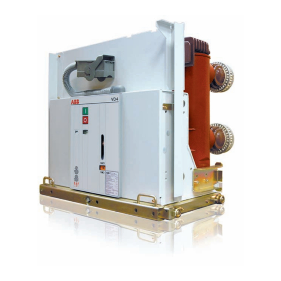
Vacuum circuit-breaker with embeded poles
Hide thumbs
Also See for VD4:
- Installation and service instructions manual (73 pages) ,
- Product manual (56 pages) ,
- Instruction manual (44 pages)

Related Manuals for ABB VD4


Summary of Contents for ABB VD4
- Page 1 VD4 Vacuum Circuit-breaker With Embeded Poles 36...40.5 kV, 1250...2500A, 25...31.5kA Instruction Manual...
- Page 3 Your safety first always! That's why our instruction manual begins with these recommendations: Only install switchgear and/or switchboards in enclosed rooms suitable for electrical equipment. Ensure that installation, operation and maintenance are carried out by specialist electricians only. Comply in full with the legally recognized standards, the connection conditions of the local electrical utility and the applicable safety at work regulations.
-
Page 4: Table Of Contents
Contents Page Contents Page Summary Despatch and storage General Condition on delivery Standards and specifications Packaging 1.2.1 Switchgear manufacture Transport 1.2.2 Installation and operation Delivery Operating conditions Intermediate storage 1.3.1 Normal operating conditions Installation 1.3.2 Special operating conditions Commissioning/Operation Technical data Note on safety at work Technical data Preparatory activities... -
Page 5: Summary
- Health and Safety at Work Standard VBG 4 General Safety guidelines for auxiliary and operating ● The vacuum circuit-breakers of type VD4 on with- materials drawable parts for 36 kV or 40.5 kV rated voltage Order related details provided by are intended for indoor installation in air-insulated ●... -
Page 6: Technical Data
Fixed With- Fixed With- current, current, current, draw- draw- symm. asymmetr. (peak.) able able VD4... approx. kg 3612-25 36 1250 27.3 360 280 320 290 3616-25 36 1600 320 290 3620-25 36 2000 355 340 3625-25 36 2500... -
Page 7: Technical Data
Technical data Releases and blocking magnet Equipment Power consumption Shunt release OFF , Y9 , Y9 Shunt release ON 3) 4) Blocking magnet Undervoltage release undelayed delayed Indirect overcurrent release with intermediate current transformer two-phase three-phase Approximate values With short-circuited intermediate current transformer Auxiliary voltages AC: 110 and 220 V, DC: 24, 48, 60, 110 and 220 V. -
Page 8: Permissible Number Of Vacuum
30 40 60 Breaking current I (kA) Breaking current I (kA) a) Circuit-breaker type VD4, 36 kV and 40.5 kV b) Circuit-breaker type VD4, 36 kV and 40.5 kV Rated short-circuit breaking current 25 kA Rated short-circuit breaking current 31.5 kA... -
Page 9: Dimensions
2000/2500A Note: O 113 O 79 Transport bracket TK (147) and transport profile TP (148) only fitted for handling. Remove and store prior to commissioning. Fig. 2/2 Dimension of withdrable VD4 40.5kV DETAIL A 4- 11 61 139.5 1065 1105... - Page 10 2) Spring in the diagram is discharged. Standard configurations and S1, S2, S3, S4, S8, S9 options available for VD4 are contained in the diagram. Also see Any requirement exceed mentioned above, should be relative catalogues and order forms for all possible configuration.
- Page 11 Fig. 2/5 Circuit diagram for withdrawable VD4...
- Page 12 Fig. 2/6 Circuit diagram for fixed VD4...
-
Page 13: Structure And Function
Charging condition indicator 55.8 for the stored ● The 36 kV and 40.5 kV circuit-breakers of type energy spring VD4 are designed as withdrawable units. The Mechanical operating cycle counter 55.5. ● poles, which are constructed in column form, are... -
Page 14: Function
Auxiliary switch S5 can be optionally designed drive shaft 55.30 to be rotated by the (previously) with any possible combination of contacts from charged spiral spring. The moving contact 58.3 five NOCs to five NCCs. Its contacts are available in vacuum interrupter 58 is moved until the contacts for any required control, annunciation or touch by cam disk and further kinematic links. - Page 15 50.2 57.1 57.8 57.2 50.1 50.8 Figure 3/1: Withdrawable part with circuit-breaker, type VD4, Figure 3/2: Withdrawable part with circuit-breaker, type VD4, operator's side pole side 50.1 Earthing contact 50.2 Front partition plate 50.8 Wheel 57.1 Upper contact arm 57.2 Lower contact arm 57.8...
- Page 16 51.2 51.1 50.1 50.4 50.3 50.4 50.3 Figure 3/4: Withdrawable part with circuit-breaker, type VD4, Figure 3/5: Withdrawable part with circuit-breaker, type VD4, left and operator's side view (pole side, below) Frame of the withdrawable part 50.1 Earthing contact 50.3 Actuating pin 50.3...
- Page 17 Figure 3/7: Vacuum circuit-breaker, type VD4, for fixed installation, Figure 3/8: Vacuum circuit-breaker, type VD4, for fixed operating side. installation, terminal side. 50.8 Rollers 57.1 Upper breaker terminal 57.2 Lower breaker terminal 57.8 Embedded pole Figure 3/10: Indicators and controls on a circuit-breaker for fixed installation.
-
Page 18: Despatch And Storage
● trolley jack. ● Figure 4/1: VD4 breaker on withdrawable part Figure 4/2: VD4 breaker for fixed installation Only handle by crane when the transport bracket Only handle by crane when the lifting lugs are fitted. 147 and crane harness are fitted.Always bear in... -
Page 19: Delivery
Delivery Installation The duties of the consignee on receipt of (Figures 3/4, 4/1 and 4/2) the switching devices at site include the following: Perfect operation of the circuit-breaker depends Checking the delivery for completeness ● on careful and professional handling of and freedom from damage (e.g. -
Page 20: Commissioning/Operation
Insert charging lever 128 into the socket 55.6 Commissioning/Operation ● and pump up and down for approx. 25 strokes (Figures: 3/2, 3/3, 3/10, 6/1 to 6/7) until the charged condition is displayed. Note on safety at work When the charged condition is reached, ●...