Siemens SIMATIC ET 200SP Equipment Manual
Digital output module rq 4x120vdc-230vac/5a no ma st
Hide thumbs
Also See for SIMATIC ET 200SP:
- System manual (320 pages) ,
- Manual (270 pages) ,
- Operating instructions manual (166 pages)
Table of Contents
Advertisement
Quick Links
Advertisement
Table of Contents

Related Manuals for Siemens SIMATIC ET 200SP


Summary of Contents for Siemens SIMATIC ET 200SP
- Page 2 Preface ET 200SP Documentation Guide SIMATIC Product overview Wiring ET 200SP Digital output module RQ 4x120VDC-230VAC/5A NO MA ST Parameters/address space (6ES7132-6MD00-0BB1) Interrupts/diagnostics alarms Equipment Manual Technical specifications Parameter data record A5E36107692-AB...
- Page 3 Note the following: WARNING Siemens products may only be used for the applications described in the catalog and in the relevant technical documentation. If products and components from other manufacturers are used, these must be recommended or approved by Siemens. Proper transport, storage, installation, assembly, commissioning, operation and maintenance are required to ensure that the products operate safely and without any problems.
-
Page 4: Preface
Purpose of the documentation This manual supplements the ET 200SP distributed I/O system (https://support.automation.siemens.com/WW/view/en/58649293) system manual. Functions that generally relate to the system are described in this system manual. The information provided in this manual and in the system/function manuals supports you in commissioning the system. - Page 5 Siemens' products and solutions undergo continuous development to make them more secure. Siemens strongly recommends that product updates are applied as soon as they are available and that the latest product versions are used. Use of product versions that are no longer supported, and failure to apply the latest updates may increase customers' exposure to cyber threats.
-
Page 6: Table Of Contents
Table of contents Preface ..............................3 ET 200SP Documentation Guide ......................6 Product overview ........................... 8 Properties ..........................8 Wiring ..............................10 Wiring and block diagram ....................10 Parameters/address space ........................14 Parameters ........................14 Explanation of the parameters ................... 16 Address space ........................ -
Page 7: Et 200Sp Documentation Guide
This arrangement enables you to access the specific content you require. Basic information The System Manual and Getting Started describe in detail the configuration, installation, wiring and commissioning of the SIMATIC ET 200SP distributed I/O system. The STEP 7 online help supports you in the configuration and programming. Device information Product manuals contain a compact description of the module-specific information, such as properties, wiring diagrams, characteristics and technical specifications. - Page 8 You can download the product information free of charge from the Internet (https://support.industry.siemens.com/cs/us/en/view/73021864). Manual Collection ET 200SP The Manual Collection contains the complete documentation on the SIMATIC ET 200SP distributed I/O system gathered together in one file. You can find the Manual Collection on the Internet (https://support.automation.siemens.com/WW/view/en/84133942).
-
Page 9: Product Overview
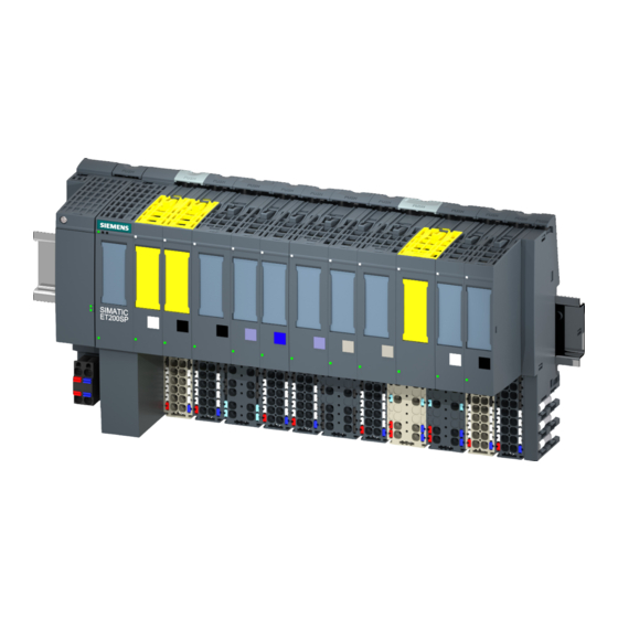
Product overview Properties Article number 6ES7132-6MD00-0BB1 View of the module ① Module type and name ⑧ Toggle/jog switch for manually controlling the relay ② LED for diagnostics ⑨ Color coding of module type ③ JOG (switch position up: jog) ⑩ Function and firmware version AUT (switch position "middle": Automatic mode ON (switch position down: Manual mode (MANUAL ON)) - Page 10 • Reference identification label • Shield connector See also You can find additional information on the accessories in the system manual ET 200SP distributed I/O system (http://support.automation.siemens.com/WW/view/en/58649293). Digital output module RQ 4x120VDC-230VAC/5A NO MA ST (6ES7132-6MD00-0BB1) Equipment Manual, , A5E36107692-AB...
-
Page 11: Wiring
2-wire and 3-wire connection. You can find information on wiring the BaseUnit in the system manual ET 200SP distributed I/O system (http://support.automation.siemens.com/WW/view/en/58649293). Note You can use and combine the different wiring options for all channels. - Page 12 Wiring 3.1 Wiring and block diagram Wiring: 3-wire connection of actuators The following figure shows the block diagram and an example of the terminal assignment of the digital output module RQ 4x120VDC-230VAC/5A NO MA ST on the BaseUnit BU type B0. ①...
- Page 13 Wiring 3.1 Wiring and block diagram Wiring: 2-wire connection of actuators The following figure shows the block diagram and an example of the terminal assignment of the digital output module RQ 4x120VDC-230VAC/5A NO MA ST on the BaseUnit BU type B1. ①...
- Page 14 Wiring 3.1 Wiring and block diagram Toggle/jog switch for controlling the relay You can switch the relay using the toggle/jog switch to jog, MANUAL ON (manual mode) or automatic mode for each channel. In manual mode, the state set by the output data is ignored.
-
Page 15: Parameters/Address Space
Parameters/address space Parameters Parameters for RQ 4x120VDC-230VAC/5A NO MA ST The effective range of the configurable parameters depends on the type of configuration. The following configurations are possible: • Central operation with an ET 200SP CPU • Distributed operation on PROFINET IO in an ET 200SP system •... - Page 16 Parameters/address space 4.1 Parameters Parameter Range of values Default Parameter Effective range with configura- reassign- tion software, e.g. STEP 7 ment in RUN (TIA Portal) GSD file GSD file PROFINET IO PROFIBUS DP Reaction to CPU STOP Turn off Channel Module •...
-
Page 17: Explanation Of The Parameters
See also You can find additional information in the system manual ET 200SP distributed I/O system (http://support.automation.siemens.com/WW/view/en/58649293). Digital output module RQ 4x120VDC-230VAC/5A NO MA ST (6ES7132-6MD00-0BB1) Equipment Manual, , A5E36107692-AB... -
Page 18: Address Space
Parameters/address space 4.3 Address space Address space The module can be configured differently in STEP 7; see following table. Depending on the configuration, additional/different addresses are assigned in the process image output/input. Configuration options of RQ 4×120VDC-230VAC/5A NO MA ST You can configure the module with STEP 7 (TIA Portal) or with a GSD file. - Page 19 Parameters/address space 4.3 Address space Address space The following figure shows the assignment of the address space for the RQ 4×120VDC-230VAC/5A NO MA ST with value status (Quality Information (QI)). The addresses for the value status are only available if the value status is enabled. Figure 4-1 Address space of RQ 4×120VDC-230VAC/5A NO MA ST with value status Digital output module RQ 4x120VDC-230VAC/5A NO MA ST (6ES7132-6MD00-0BB1)
-
Page 20: Interrupts/Diagnostics Alarms
Interrupts/diagnostics alarms Status and error display LED display The following figure shows you the LED display of the RQ 4x120VDC-230VAC/5A NO MA ST. ① DIAG (green/red) ② MA .0 .. .3 (yellow) ③ Channel status (green) ④ PWR (green) Figure 5-1 LED display Meaning of the LEDs The following tables show the meaning of the status and error displays. - Page 21 Interrupts/diagnostics alarms 5.1 Status and error display DIAG LED Table 5- 1 Error display of the DIAG LED DIAG LED Meaning Backplane bus supply of the ET 200SP not OK Off Module not ready for operation (no parameters assigned) Flashes Module parameters assigned and no module diagnostics Module parameters assigned and module diagnostics Flashes...
-
Page 22: Interrupts
Interrupts/diagnostics alarms 5.2 Interrupts Interrupts The digital output module RQ 4×120VDC-230VAC/5A NO MA ST supports diagnostics interrupts. Diagnostics interrupts The module generates a diagnostic interrupt at the following events: • Parameter assignment error • Supply voltage missing • Channel temporarily unavailable Diagnostics alarms A diagnostics alarm is generated and the DIAG-LED flashes on the module for each diagnostics event. -
Page 23: Technical Specifications
Technical specifications Technical specifications of the RQ 4×120VDC-230VAC/5A NO MA ST The following table shows the technical specifications as of 06/2020. You will find a data sheet including daily updated technical specifications on the Internet (https://support.industry.siemens.com/cs/ww/en/pv/6ES7132-6MD00-0BB1/td?dl=en). Article number 6ES7132-6MD00-0BB1 General information Product type designation RQ 4x120 V DC ... - Page 24 Technical specifications 6.1 Technical specifications Article number 6ES7132-6MD00-0BB1 Input current Current consumption, max. 100 mA; without load Power loss Power loss, typ. 1.5 W Address area Address space per module 1 byte; With QI • Inputs 1 byte • Outputs Hardware configuration Automatic encoding •...
- Page 25 Technical specifications 6.1 Technical specifications Article number 6ES7132-6MD00-0BB1 7 000 000; see additional description in the man- • Number of operating cycles, max. Switching capacity of contacts 2 A; see additional description in the manual with inductive load, max. – 5 A;...
- Page 26 Technical specifications 6.1 Technical specifications Article number 6ES7132-6MD00-0BB1 tested with 2 500 V DC • between channels and backplane bus/supply voltage 707 V DC (type test) • between backplane bus and supply voltage Standards, approvals, certificates Suitable for safety functions Ambient conditions Ambient temperature during operation -30 °C...
- Page 27 The following figure show the load current derating with horizontal and vertical mounting positions. Figure 6-1 Load current for mounting position Dimension drawing See manual ET 200SP BaseUnits (http://support.automation.siemens.com/WW/view/en/59753521) Digital output module RQ 4x120VDC-230VAC/5A NO MA ST (6ES7132-6MD00-0BB1) Equipment Manual, , A5E36107692-AB...
-
Page 28: Switching Cycles
Technical specifications 6.2 Switching cycles Switching cycles Switching capacity and lifetime of the contacts With an external protective circuit, the contacts will last longer than specified in the table. This table shows the switching capacity and lifetime of the relay contacts: Table 6- 1 Switching capacity and lifetime of the relay contacts Resistive load... - Page 29 Technical specifications 6.2 Switching cycles Note Tests of mechanical environmental conditions Shock tested according to IEC 60068-2-27. Shock intensity: 100 m/s peak value, 11 ms duration Digital output module RQ 4x120VDC-230VAC/5A NO MA ST (6ES7132-6MD00-0BB1) Equipment Manual, , A5E36107692-AB...
-
Page 30: Parameter Data Record
Parameter data record Parameter assignment and structure of the parameter data record The data record of the module has an identical structure, regardless of whether you configure the module with PROFIBUS DP or PROFINET IO. With data record 128, you can reconfigure the module in your user program regardless of your programming. - Page 31 Parameter data record A.1 Parameter assignment and structure of the parameter data record Figure A-1 Structure of data record 128 Header information The figure below shows the structure of the header information. Figure A-2 Header information Parameters The figure below shows the structure of the parameters in data record 128. You enable a parameter by setting the corresponding bit to "1".
- Page 32 Parameter data record A.1 Parameter assignment and structure of the parameter data record Figure A-3 Structure byte x to x+1 for the channels 0 to 3 Error transmitting the data record The module always checks all values of the data record to be sent. The module applies the values from the data record only when all values have been transmitted without errors.