Siemens RUGGEDCOM RS416 Installation Manual
Hide thumbs
Also See for RUGGEDCOM RS416:
- Installation manual (42 pages) ,
- Installation manual (50 pages)

Related Manuals for Siemens RUGGEDCOM RS416


Summary of Contents for Siemens RUGGEDCOM RS416
- Page 1 Installation Manual SIMATIC NET Rugged Ethernet Switches RUGGEDCOM RS416 Edition 11/2020 https://www.siemens.com...
- Page 2 Preface Introduction Installing Device SIMATIC NET Device Management Rugged Ethernet Switches RUGGEDCOM RS416 Communication Ports Technical Specifications Installation Manual Certification 11/2020 C79000-G8976-1018-09...
- Page 3 Note the following: WARNING Siemens products may only be used for the applications described in the catalog and in the relevant technical documentation. If products and components from other manufacturers are used, these must be recommended or approved by Siemens. Proper transport, storage, installation, assembly, commissioning, operation and maintenance are required to ensure that the products operate safely and without any problems.
-
Page 4: Table Of Contents
Related Documents ......................... v Registered Trademarks ......................v Warranty ..........................v Training ..........................vi Customer Support ........................vi Contacting Siemens ........................ vi Introduction ........................... 1 Feature Highlights ....................1 Description ......................2 Required Tools and Materials ................. 4 Decommissioning and Disposal ................4 Cabling Recommendations .................. - Page 5 FCC ........................38 6.1.4 FDA/CDRH ......................39 6.1.5 ISED ........................39 6.1.6 ISO ........................39 6.1.7 ACMA ........................39 6.1.8 RoHS ........................40 6.1.9 Other Approvals ....................40 EMC and Environmental Type Tests ..............40 RUGGEDCOM RS416 Installation Manual, 11/2020, C79000-G8976-1018-09...
-
Page 6: Preface
Warranty Siemens warrants this product for a period of five (5) years from the date of purchase, conditional upon the return to factory for maintenance during the warranty term. This product contains no user-serviceable parts. Attempted service by unauthorized personnel shall render all warranties null and void. -
Page 7: Training
Siemens Sales representative. Customer Support Customer support is available 24 hours, 7 days a week for all Siemens customers. For technical support or general information, contact Siemens Customer Support through any of the following methods: Online Visit http://www.siemens.com/automation/support-request... - Page 8 Preface Contacting Siemens 300 Applewood Crescent Concord, Ontario Canada, L4K 5C7 Telephone Toll-free: 1 888 264 0006 Tel: +1 905 856 5288 Fax: +1 905 856 1995 E-Mail ruggedcom.info.i-ia@siemens.com https://www.siemens.com RUGGEDCOM RS416 Installation Manual, 11/2020, C79000-G8976-1018-09...
- Page 9 Preface Contacting Siemens viii RUGGEDCOM RS416 Installation Manual, 11/2020, C79000-G8976-1018-09...
-
Page 10: Introduction
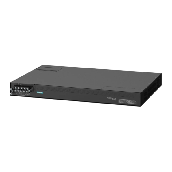
Featuring a modular design that can support IEEE 1588 and IRIG-B time synchronization, up to 16 serial ports and up to four Ethernet ports, the RUGGEDCOM RS416 is able to interconnect and synchronize multiple types of intelligent electronic devices (IEDs). -
Page 11: Description
CSA/UL 60950-1 safety approved to 85 °C (185 °F) Description The RUGGEDCOM RS416 features various ports, controls and indicator LEDs on the display panel for connecting, configuring and troubleshooting the device. The display panel can be located on the rear, front or top of the device, depending on the mounting configuration. - Page 12 RS-232 Serial Console Port (RJ45) Figure 1.1 RUGGEDCOM RS416 Communication Ports Ports for communicating with other devices or accessing the RUGGEDCOM RUGGEDCOM RS416 operating system are described "Communication Ports (Page 23)". Port Status Indicator LEDs Port status indicator LEDs indicate the operational status of each port, dependent on the currently selected mode.
-
Page 13: Required Tools And Materials
"Connecting to the Device (Page 21)". Required Tools and Materials The following tools and materials are required to install the RUGGEDCOM RS416: Tools/Materials Purpose AC power cord (16 AWG) For connecting power to the device. -
Page 14: Cabling Recommendations
Siemens also does not recommend using copper Ethernet ports to interface with devices in the field across distances that could produce high levels of ground potential rise (i.e. greater than 2500 V), during line-to-ground fault conditions. -
Page 15: 1.6.1 Supported Time Synchronization Sources
GPS receiver at each node or for which GPS signals are inaccessible. The RUGGEDCOM RS416 only supports ordinary clock mode. An ordinary clock can be configured as either a Grandmaster Clock (GM) or a Slave Clock (SC) within the master-slave hierarchy. -
Page 16: Ttl Outputs
Introduction 1.6.2 TTL Outputs Every Ethernet port on the RUGGEDCOM RS416 supports IEEE 1588. For more information, refer to "IEEE 1588 Support (Page 7)". 1.6.2 TTL Outputs The PTP card provides a TTL (Transistor-Transistor Logic) output. The TTL OUT port supports the IRIG-B PWM and PPS signal formats. Enabling/ disabling the output port and selecting the signal format is controlled through the RUGGEDCOM RS416 operating system. - Page 17 Introduction 1.6.3 IEEE 1588 Support • Peer-to-Peer Slave Clock • Peer-to-Peer Master Clock RUGGEDCOM RS416 Installation Manual, 11/2020, C79000-G8976-1018-09...
-
Page 18: Installing Device
This product contains no user-serviceable parts. Attempted service by unauthorized personnel shall render all warranties null and void. Changes or modifications not expressly approved by Siemens AG could invalidate specifications, test results, and agency approvals, and void the user's authority to operate the equipment. -
Page 19: Mounting The Device
If any item is missing or damaged, contact Siemens for assistance. Mounting the Device The RUGGEDCOM RS416 is designed for maximum mounting and display flexibility. It can be equipped with connectors that allow it to be installed in a 48 cm (19 in) rack, 35 mm (1.4 in) DIN rail, or directly on a panel. -
Page 20: Mounting The Device On A Din Rail
2.2.2 Mounting the Device on a DIN Rail For DIN rail installations, the RUGGEDCOM RS416 can be equipped with panel/DIN rail adapters pre-installed on each side of the chassis. The adapters allow the device to be slid onto a standard 35 mm (1.4 in) DIN rail. -
Page 21: 2.2.3 Mounting The Device To A Panel
2.2.3 Mounting the Device to a Panel For panel installations, the RUGGEDCOM RS416 can be equipped with panel/DIN rail adapters pre-installed on each side of the chassis. The adapters allow the device to be attached to a panel using screws. -
Page 22: Connecting The Failsafe Alarm Relay
NO contact and closes the NC (Normally Closed) contact. Note Control of the failsafe relay output is configurable through RUGGEDCOM RS416 . One common application for this relay is to signal an alarm if a power failure occurs. For more information, refer to the RUGGEDCOM RS416 User Guide for the RUGGEDCOM RS416. -
Page 23: Grounding The Device
Figure 2.4 Failsafe Alarm Relay Wiring Grounding the Device The RUGGEDCOM RS416 chassis ground terminal uses a #6-32 screw. It is recommended to terminate the ground connection with a #6 ring lug and torque it to 1.7 N·m (15 lbf·in). Stainless Steel Stud... -
Page 24: Connecting Power
Installing Device 2.5 Connecting Power Connecting Power The RUGGEDCOM RS416 supports single or dual redundant high AC and/or low DC power supplies. The RUGGEDCOM RS416 can be equipped with either a screw-type or pluggable terminal block, which provides power to both internal power modules. The screw- type terminal block is installed using Phillips screws and compression plates, allowing either bare wire connections or crimped terminal lugs. - Page 25 Connect the positive wire from the power source to the positive/live (+/L) terminal on the terminal block. Screw-Type Terminal Block Pluggable Terminal Block Jumper Positive/Live (+/L) Terminal Negative/Neutral (-/N) Terminal (-/N) Surge Ground Terminal Chassis Ground Terminal Figure 2.6 Terminal Block Wiring RUGGEDCOM RS416 Installation Manual, 11/2020, C79000-G8976-1018-09...
-
Page 26: 2.5.2 Wiring Examples
Make sure the supplied terminal block cover is always installed before the device is powered. Install the terminal block cover. 2.5.2 Wiring Examples The following illustrate how to connect power to single and dual power supplies. Figure 2.7 Single AC Power Supply RUGGEDCOM RS416 Installation Manual, 11/2020, C79000-G8976-1018-09... - Page 27 Installing Device 2.5.2 Wiring Examples Figure 2.8 Single DC Power Supply Figure 2.9 Dual AC Power Supply RUGGEDCOM RS416 Installation Manual, 11/2020, C79000-G8976-1018-09...
- Page 28 Installing Device 2.5.2 Wiring Examples Figure 2.10 Dual DC Power Supply Figure 2.11 Dual AC/DC Power Supply RUGGEDCOM RS416 Installation Manual, 11/2020, C79000-G8976-1018-09...
- Page 29 Installing Device 2.5.2 Wiring Examples RUGGEDCOM RS416 Installation Manual, 11/2020, C79000-G8976-1018-09...
-
Page 30: Device Management
This section describes how to connect to and manage the device. Connecting to the Device The following describes the various methods for accessing the RUGGEDCOM RS416 console and Web interfaces on the device. For more detailed instructions, refer to the RUGGEDCOM RS416 User Guide for the RUGGEDCOM RS416. -
Page 31: Configuring The Device
Communication Ports Connect any of the available Ethernet ports on the device to a management switch and access the RUGGEDCOM RS416 console and Web interfaces via the device's IP address. For more information about available ports, refer to "Communication Ports (Page 23)". -
Page 32: Communication Ports
Communication Ports The RUGGEDCOM RS416 can be equipped with various types of communication ports to enhance its abilities and performance. Each communication port type has a specific place in the RUGGEDCOM RS416 chassis. Slot 1 Slot 2 Slot 3 Slot 4... -
Page 33: Fiber Optic Ethernet Ports
Registered Jack), LC (Lucent Connector), SC (Standard or Subscriber Connector) or ST (Straight Tip) connectors. Make sure the Transmit (Tx) and Receive (Rx) connections of each port are properly connected and matched to establish a proper link. RUGGEDCOM RS416 Installation Manual, 11/2020, C79000-G8976-1018-09... -
Page 34: Serial Ports
Note On power-up, all serial RJ45 ports default to RS485 mode. Each port can be individually set to RS232, RS485 or RS422 mode through RUGGEDCOM RS416 . For more information, refer to the RUGGEDCOM RS416 User Guide for the RUGGEDCOM RS416. - Page 35 Pins 1, 4 and 6 and pins 7 and 8 are connected internally. In RS232 mode, these pins enter a high impedance state. A DTE that asserts RTS will see CTS asserted. However, the device will not perform hardware flow control. RUGGEDCOM RS416 Installation Manual, 11/2020, C79000-G8976-1018-09...
- Page 36 Pins 1, 2 and 3 and pins 7 and 8 are connected internally. In RS232 mode, these pins enter a high impedance state. A DTE that asserts RTS will see CTS asserted. However, the device will not perform hardware flow control. RUGGEDCOM RS416 Installation Manual, 11/2020, C79000-G8976-1018-09...
-
Page 37: Bnc Ports
TTL IN Port Figure 4.12 PTP Module Inputs are controlled by RUGGEDCOM RS416 and only one can be active at any time. For information about activating an input, refer to the RUGGEDCOM RUGGEDCOM RS416 User Guide for the RUGGEDCOM RS416. The color of the Sync LED on the front panel of the PTP module indicates the status of the incoming timing signal: •... -
Page 38: Connecting Multiple Rs485 Devices
• The twisted pair should be terminated at each end of the chain. The following shows the recommended RS485 wiring. 120Ω 10nF 120Ω 10nF RUGGEDCOM RS416 Common (Isolated Ground) Negative Positive Shield to Earth (Connected At a Single Point) RUGGEDCOM RS416... - Page 39 Communication Ports 4.5 Connecting Multiple RS485 Devices RS485 Devices (32 Total) Figure 4.13 Recommended RS485 Wiring RUGGEDCOM RS416 Installation Manual, 11/2020, C79000-G8976-1018-09...
-
Page 40: Technical Specifications
Maximum Switching Voltage Rated Switching Current 30 VAC 0.3 A, 1.0 A 80 VDC Copper Ethernet Port Specifications The following details the specifications for copper Ethernet ports that can be ordered with the RUGGEDCOM RS416. Speed 10/100Base-TX Connector RJ45 Duplex FDX/HDX Cable Type >... -
Page 41: Fiber Optic Ethernet Port Specifications
Typical distance. Dependent on the number of connectors and splices. RMS 1 minute. Fiber Optic Ethernet Port Specifications The following details specifications for the fiber optic Ethernet ports that can be equipped on the RUGGEDCOM RS416. 10Base-FL Ethernet Optical Ports Power Connector Cable Tx λ... -
Page 42: Serial Port Specifications
100 mA Output Voltage (V TTL-Compatible Output Impedance (R 50 Ω Operating Environment The RUGGEDCOM RS416 is rated to operate under the following environmental conditions. Ambient Operating -40 to 85 °C (-40 to 185 °F) Temperature Ambient Storage Temperature -40 to 85 °C (-40 to 185 °F) -
Page 43: Mechanical Specifications
Measured from a 30 cm (12 in) radius surrounding the center of the enclosure. Non-condensing. Mechanical Specifications Weight 4.5 kg (10 lbs) Ingress Protection IP20 Enclosure 18 AWG Galvanized Steel Dimension Drawings Note All dimensions are in millimeters, unless otherwise stated. 438.15 Figure 5.1 Overall Dimensions RUGGEDCOM RS416 Installation Manual, 11/2020, C79000-G8976-1018-09... - Page 44 Technical Specifications 5.9 Dimension Drawings 479.30 11.68 461.01 21.08 32.64 4.57 Figure 5.2 Rack Mount Dimensions 486.4 476.3 10.4 11.7 Figure 5.3 Panel and DIN Rail Mount Dimensions RUGGEDCOM RS416 Installation Manual, 11/2020, C79000-G8976-1018-09...
- Page 45 Technical Specifications 5.9 Dimension Drawings RUGGEDCOM RS416 Installation Manual, 11/2020, C79000-G8976-1018-09...
-
Page 46: Certification
Information Technology Equipment - Safety - Part 1: General Requirements The device is marked with a CSA symbol that indicates compliance with both Canadian and U.S. requirements. A copy of the CSA Certificate of Compliance is available via Siemens Industry Online Support at https://support.industry.siemens.com/cs/ww/en/view/109476557. 6.1.2... -
Page 47: 6.1.3 Fcc
Safety of Laser Products – Equipment Classification and Requirements The device is marked with a CE symbol and can be used throughout the European community. A copy of the EU Declaration of Conformity is available via Siemens Industry Online Support at https://support.industry.siemens.com/cs/ww/en/view/109475474. 6.1.3 This device has been tested and found to comply with the limits for a Class A digital device, pursuant to Part 15 of the FCC Rules. -
Page 48: Fda/Cdrh
Title 21 Code of Federal Regulations (CFR) – Chapter I – Sub-chapter J – Radiological Health 6.1.5 ISED This device is declared by Siemens AG to meet the requirements of the following ISED (Innovation Science and Economic Development Canada) standard: • CAN ICES-3 (A)/NMB-3 (A) 6.1.6... -
Page 49: 6.1.8 Rohs
Certification 6.1.8 RoHS 6.1.8 RoHS This device is declared by Siemens AG to meet the requirements of the following RoHS (Restriction of Hazardous Substances) directives for the restricted use of certain hazardous substances in electrical and electronic equipment: • China RoHS 2... - Page 50 ports AC Power 2 kV ports HV Impulse Signal ports 5 kV (Fail-Safe Relay Output) DC Power 5 kV ports AC Power 5 kV ports Siemens specified severity level. RUGGEDCOM RS416 Installation Manual, 11/2020, C79000-G8976-1018-09...
- Page 51 Certification 6.2 EMC and Environmental Type Tests IEEE 1613 EMC Immunity Type Tests Note The RUGGEDCOM RS416 meets Class 2 requirements for an all-fiber configuration and Class 1 requirements for copper ports. Description Test Levels Enclosure Contact ± 8 kV Enclosure Air ±...
- Page 52 Further Information Siemens RUGGEDCOM https://www.siemens.com/ruggedcom Industry Online Support (service and support) https://support.industry.siemens.com Industry Mall https://mall.industry.siemens.com Siemens AG Digital Industry Process Automation Postfach 48 48 90026 NÜRNBERG GERMANY...