Siemens SIMATIC ET 200SP Manual
Technology module tm pto 2x24v
Hide thumbs
Also See for SIMATIC ET 200SP:
- System manual (320 pages) ,
- Manual (270 pages) ,
- Operating instructions manual (166 pages)
Table of Contents
Advertisement
Quick Links
Advertisement
Table of Contents

Related Manuals for Siemens SIMATIC ET 200SP


Summary of Contents for Siemens SIMATIC ET 200SP
- Page 2 Technology module TM PTO 2x24V (6ES7138-6EB00-0BA0) Preface Documentation guide SIMATIC Product overview Connecting ET 200SP Technology module TM PTO 2x24V Configuring/address space (6ES7138‑6EB00‑0BA0) Interrupts/diagnostic alarms Equipment Manual Technical specifications Parameter data record 09/2021 A5E50983437-AA...
- Page 3 Note the following: WARNING Siemens products may only be used for the applications described in the catalog and in the relevant technical documentation. If products and components from other manufacturers are used, these must be recommended or approved by Siemens. Proper transport, storage, installation, assembly, commissioning, operation and maintenance are required to ensure that the products operate safely and without any problems.
-
Page 4: Preface
• mySupport Your personal working area in Industry Online Support for messages, support queries, and configurable documents. This information is provided by the Siemens Industry Online Support in the Internet (https://support.industry.siemens.com). Technology module TM PTO 2x24V (6ES7138‑6EB00‑0BA0) Equipment Manual, 09/2021, A5E50983437-AA... - Page 5 Preface Industry Mall The Industry Mall is the catalog and order system of Siemens AG for automation and drive solutions on the basis of Totally Integrated Automation (TIA) and Totally Integrated Power (TIP). You can find catalogs for all automation and drive products on the Internet (https://mall.industry.siemens.com) and in the Information and Download Center...
-
Page 6: Table Of Contents
Table of contents Preface ..............................3 Documentation guide ..........................6 ET 200SP Documentation Guide ................... 6 Product overview ..........................11 Properties .......................... 11 Functions .......................... 14 2.2.1 Pulse Train Output (PTO) ....................14 Connecting ............................17 Pin assignment ........................17 Configuring/address space ........................ -
Page 7: Documentation Guide
This arrangement enables you to access the specific content you require. Basic information The System Manual and Getting Started describe in detail the configuration, installation, wiring and commissioning of the SIMATIC ET 200SP distributed I/O system. The STEP 7 online help supports you in the configuration and programming. Device information Product manuals contain a compact description of the module-specific information, such as properties, wiring diagrams, characteristics and technical specifications. - Page 8 You can download the product information free of charge from the Internet (https://support.industry.siemens.com/cs/us/en/view/73021864). Manual Collection ET 200SP The Manual Collection contains the complete documentation on the SIMATIC ET 200SP distributed I/O system gathered together in one file. You can find the Manual Collection on the Internet (https://support.industry.siemens.com/cs/ww/en/view/84133942).
- Page 9 • Manuals, characteristics, operating manuals, certificates • Product master data You can find "mySupport" - CAx data on the Internet (http://support.industry.siemens.com/my/ww/en/CAxOnline). Application examples The application examples support you with various tools and examples for solving your automation tasks. Solutions are shown in interplay with multiple components in the system - separated from the focus on individual products.
- Page 10 You can find the SIMATIC Automation Tool on the Internet (https://support.industry.siemens.com/cs/ww/en/view/98161300). PRONETA SIEMENS PRONETA (PROFINET network analysis) allows you to analyze the plant network during commissioning. PRONETA features two core functions: • The topology overview automatically scans the PROFINET and all connected components.
- Page 11 1.1 ET 200SP Documentation Guide SINETPLAN SINETPLAN, the Siemens Network Planner, supports you in planning automation systems and networks based on PROFINET. The tool facilitates professional and predictive dimensioning of your PROFINET installation as early as in the planning stage. In addition, SINETPLAN supports you during network optimization and helps you to exploit network resources optimally and to plan reserves.
-
Page 12: Product Overview
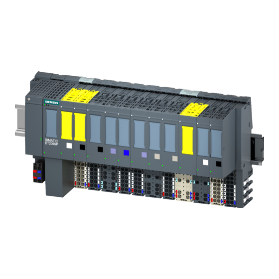
Product overview Properties Article number 6ES7138-6EB00-0BA0 View of the module ① Module type and designation ⑦ Function class ② LED for diagnostics ⑧ Module type color coding ③ 2D matrix code for reading article and serial ⑨ Function and firmware version numbers ④... - Page 13 Product overview 2.1 Properties Introduction The technology module offers you the possibility to connect up to two stepper motor axes to an ET 200SP system. The module is linked to technology objects by means of an implementation of the PROFIdrive telegrams 1 and 81 and forms the interface to the drive. The number of steps that are output is returned as the actual position value.
- Page 14 BaseUnits to be used with the technology module, refer to the product information on the documentation for the ET 200SP Distributed I/O System (http://support.automation.siemens.com/WW/view/en/73021864). For additional information on the accessories, refer to the ET 200SP Distributed I/O System (http://support.automation.siemens.com/WW/view/en/58649293) system manual. Technology module TM PTO 2x24V (6ES7138‑6EB00‑0BA0) Equipment Manual, 09/2021, A5E50983437-AA...
-
Page 15: Functions
For a detailed description of configuring the technology module with the axis technology objects, see Function Manual S7-1500T Motion Control, section "Configuring", which is available for download on theInternet (https://support.industry.siemens.com/cs/ww/en/view/109481326). Technology module TM PTO 2x24V (6ES7138‑6EB00‑0BA0) Equipment Manual, 09/2021, A5E50983437-AA... - Page 16 Product overview 2.2 Functions Signal types The technology module supports the following four signal types: Note The pulse width is fixed depending on the maximum pulse frequency set for the respective channel. • PTO (Pulse (P) and direction (D)): One output (P) controls the pulses and one output (D) controls the direction. D is 'high' (active) when pulses are generated in the negative direction.
- Page 17 Product overview 2.2 Functions • PTO (A, B phase-shifted): Output pulses are output by both outputs at the specified velocity, but phase-shifted by 90 degrees. This involves a single pulse output in which the duration of the pulse is the time between two transitions of signal A while signal B is at low level.
-
Page 18: Connecting
ET 200SP Distributed I/O System (http://support.automation.siemens.com/WW/view/en/73021864). You can find information about selecting a suitable BaseUnit in the ET 200SP Distributed I/O system (http://support.automation.siemens.com/WW/view/en/58649293) system manual and ET 200SP BaseUnits (http://support.automation.siemens.com/WW/view/en/58532597/133300) equipment manual. You can find information on wiring the BaseUnit, connecting cable shields, etc. in the Wiring section of the ET 200SP Distributed I/O system (http://support.automation.siemens.com/WW/view/en/58649293) system manual. - Page 19 Connecting 3.1 Pin assignment Pin assignment of BaseUnit The table below shows the terminal assignment, using the BaseUnit BU15-P16+A0+2B as an example. Table 3- 1 Terminal assignment of the BaseUnit BU15-P16+A0+2B Designation Signal name View Signal name Designation Channel 0 Channel 1 Pulse signal P/A CH0.P/A...
- Page 20 Connecting 3.1 Pin assignment Circuit diagram You must ground the shields of the cables between the motor and the technology module via the shield connection to the BaseUnit (shield support and terminal). The figure below shows the block diagram of the technology module with an example using both channels.
- Page 21 Connecting 3.1 Pin assignment 24 V pulse output signals The technology module can output the 24 V pulse signals P/A and D/B per channel. For an overview of the signal types you can output, see section Pulse Train Output (PTO) (Page 14).
- Page 22 Connecting 3.1 Pin assignment Input delay for digital inputs To suppress interference, you can configure an input delay for the digital inputs. Note If you select the "None" or "0.05 ms" option, you have to use shielded cables for connection of the digital inputs.
-
Page 23: Configuring/Address Space
Configuring/address space Configuring Introduction The technology module is configured and assigned parameters with the configuration software. The user program controls and monitors the functions of the technology module via Motion Control instructions or via the control and feedback interface. Technology module TM PTO 2x24V (6ES7138‑6EB00‑0BA0) Equipment Manual, 09/2021, A5E50983437-AA... - Page 24 • Function Manual S7-1500T Motion Control, section "Configuring", which is available for download on theInternet (https://support.industry.siemens.com/cs/ww/en/view/109481326) • Information system of STEP 7 (TIA Portal), under "Using technology functions > Motion Control > Motion Control (S7-1200, S7-1500, S7-1500T) > Configuring (S7-1500, S7-1500T) >...
- Page 25 GSD file The respective GSD file for the ET 200SP distributed I/O system is available for download on the Internet: GSD file PROFINET IO (https://support.industry.siemens.com/cs/ww/en/view/68189683) GSD file PROFIBUS DP (http://support.automation.siemens.com/WW/view/en/73016883) Control via user program without technology object You can find a description of the control and feedback signals as well as a state diagram for enabling the pulse output without technology object in section Control and feedback interface (Page 30).
-
Page 26: Parameter Setting
Configuring/address space 4.2 Parameter setting Parameter setting You can use various parameters to define the properties of the technology module. Depending on the settings, not all parameters are available. When parameters are assigned in the user program, the parameters are transferred to the module with the "WRREC" instruction and data record 128 (Page 52). - Page 27 Configuring/address space 4.2 Parameter setting Parameters of the TM PTO 2x24V The following parameter settings are possible. The default settings of the parameters are shown in bold in the "Value range" column. Table 4- 1 Programmable parameters Parameter Value range Scope Potential group Module...
- Page 28 Configuring/address space 4.2 Parameter setting Parameter Value range Scope Input delay Channel • None • 0.05 ms • 0.1 ms • 0.4 ms • 0.8 ms • 1.6 ms • 3.2 ms • 12.8 ms • 20 ms Tolerated number of 0...1...65535 Channel sign-of-life errors...
- Page 29 Configuring/address space 4.2 Parameter setting Description of parameters Parameter Description Potential group A potential group consists of a group of I/O modules placed directly next to each other within an ET 200SP station, which are supplied via a common supply voltage. A potential group begins with a light-colored BaseUnit, which feeds in the required supply voltage for all modules of the potential group.
-
Page 30: Address Space
Configuring/address space 4.3 Address space Parameter Description Use MI as measuring Enables use of the measuring input signal at the Digital input MI (Page 17). input You can save the current position of the drive axis using the measuring input signal with the technology object TO_MeasuringInput. Use DR as Drive Ready Enables use of the ready signal of the drive at Digital input DR (Page 17). -
Page 31: 4.4 Control And Feedback Interface
For a detailed description of configuring the technology module with the axis technology objects, see Function Manual S7-1500T Motion Control, section "Configuring", which is available for download on theInternet (https://support.industry.siemens.com/cs/ww/en/view/109481326). The control and feedback interface of the channels is a partial implementation of the PROFIdrive interfaces "Telegram 1" und "Telegram 81". - Page 32 Configuring/address space 4.4 Control and feedback interface Byte offset Bit 7 Bit 6 Bit 5 Bit 4 Bit 3 Bit 2 Bit 1 Bit 0 relative to start address Channel ↓ ↓ G1_STW: INT: Encoder control word Acknow Activate_ Request_ Request_ Home_ Reserved...
- Page 33 Configuring/address space 4.4 Control and feedback interface Description of control bits Control bit/value Description STW1 Control_by_PLC : Coast Stop (OFF2): Pulse output cannot be controlled by the user program on the CPU. : Valid values for control of the pulse output will be sent to the module from the user program on the CPU.
- Page 34 Configuring/address space 4.4 Control and feedback interface Control bit/value Description G1_STW Activate_Parking_Sensor You use this bit to activate a sensor pause. This causes the value "0" to be returned in G1_XIST1. Acknowledging_Sensor_Error You use this bit to acknowledge an error that occurred during feedback of the actual en- coder value.
-
Page 35: Assignment Of The Feedback Interface
Configuring/address space 4.4 Control and feedback interface 4.4.2 Assignment of the feedback interface The user program receives current values and status information from the technology module by means of the feedback interface. Feedback interface The following table shows the assignment of the feedback interface: Table 4- 4 Feedback interface of the technology module Byte... - Page 36 Configuring/address space 4.4 Control and feedback interface Description of feedback bits Feedback bit/value Description ZSW1 Control_Requested This bit indicates that the module is ready to receive values from the user program for control- ling the pulse output. f_or_n_reached_or_ This bit indicates one of the following situations: exceeded •...
- Page 37 Configuring/address space 4.4 Control and feedback interface Feedback bit/value Description Value_1_Active Mode = 0 (Reference mark search): This bit indicates that the reference mark in G1_XIST2 has been read out via the reference switch input CHn.RS. Mode = 1 (Measurement on the fly): This bit indicates that a measuring input value has been read out in G1_XIST2 via the rising edge of digital input CHn.MI.
- Page 38 Configuring/address space 4.4 Control and feedback interface Error codes G1_XIST2 can contain the following error codes: Error Name Meaning code Sensor group error G1_XIST1 is invalid. A short-circuit or overload has occurred at the digital output. Sensor pause failed A sensor pause (Sensor parking) is not supported. Reference mark detec- •...
- Page 39 Configuring/address space 4.4 Control and feedback interface Reference mark search The following figure shows an example of the sequence of the detection and readout of the reference mark: Figure 4-1 Detecting the reference mark Measurement on the fly The following figure shows an example of the sequence of the acquisition and the readout of the measuring input value: Figure 4-2 Acquiring the measuring input value...
-
Page 40: Enabling The Pulse Output
Configuring/address space 4.4 Control and feedback interface 4.4.3 Enabling the pulse output State diagram The following figure shows the state diagram for enabling the pulse output: Figure 4-3 State diagram for the operation enable Technology module TM PTO 2x24V (6ES7138‑6EB00‑0BA0) Equipment Manual, 09/2021, A5E50983437-AA... -
Page 41: Reaction To Cpu Stop
Configuring/address space 4.4 Control and feedback interface Procedure To enable the pulse output, proceed as follows: 1. Set the Control_by_PLC, Enable_Setpoint and Enable_Ramp_Generator control bits to TRUE and the On_OFF1, No_Coast_Stop_OFF2, No_Quick_Stop_OFF3 and Enable_Operation bits to FALSE. State S1 is reached: Switching on of the pulse output is still inhibited. The feedback bit Switching_On_Inhibited is set to TRUE. -
Page 42: Isochronous Mode
Additional information You can find a detailed description of isochronous mode: • In the Isochronous mode function manual as a download from the Internet (https://support.industry.siemens.com/cs/ww/en/view/109755401). • In the PROFINET with STEP 7 function manual as a download from the Internet (https://support.industry.siemens.com/cs/ww/en/view/49948856). -
Page 43: Interrupts/Diagnostic Alarms
Interrupts/diagnostic alarms Status and error displays LEDs The figure below shows the LEDs (status and error displays) of the TM PTO 2x24V. ① DIAG (green/red) ⑧ PWR (green) ② Status CH0.P/A (green) ⑨ Status CH1.P/A (green) ③ Status CH0.D/B (green) ⑩... - Page 44 Interrupts/diagnostic alarms 5.1 Status and error displays Meaning of the LED displays The following tables explain the meaning of the status and error displays. Remedial measures for diagnostic alarms can be found in the section Diagnostic alarms (Page 44). Table 5- 1 Status and error displays DIAG DIAG LED Meaning...
-
Page 45: Diagnostic Alarms
"RALRM" (Read additional alarm information), in the information system of STEP 7 and in function manual Diagnostics (https://support.industry.siemens.com/cs/ww/en/view/59192926), section "System diagnostics in user program". If the module is being operated as a distributed module in an ET 200SP system with PROFIBUS DP, you have the option of reading out diagnostic data with the RDREC or RD_REC instruction using data record 0 and 1. - Page 46 Interrupts/diagnostic alarms 5.2 Diagnostic alarms Diagnostic alarms The diagnostics are displayed as plain text in STEP 7 (TIA Portal) in the online and diagnostics view. You can evaluate the error codes with the user program. The respective channel number is shown for each diagnostic information. The following diagnostics can be signaled: Table 5- 5 Diagnostic alarms, their meaning and remedies...
- Page 47 Interrupts/diagnostic alarms 5.2 Diagnostic alarms CAUTION Cross-channel diagnostics of the digital outputs The digital outputs of both channels have common diagnostics. As a result, when there is an error at one digital output, errors are automatically signaled for both channels. The pulse output of both channels is stopped in this case, regardless of whether "Enable diagnostic interrupts"...
-
Page 48: Technical Specifications
Technical specifications Article number 6ES7138-6EB00-0BA0 General information Product type designation TM PTO 2x24V usable BaseUnits BU type A0 Color code for module-specific color identification CC00 plate Product function Yes; I&M0 to I&M3 • I&M data • Isochronous mode Engineering with STEP 7 V17 with HSP or higher •... - Page 49 Technical specifications Article number 6ES7138-6EB00-0BA0 Digital input functions, parameterizable • Synchronization • Probe • Drive ready Input voltage 24 V • Rated value (DC) -5 ... +5 V • for signal "0" +11 to +30V • for signal "1" -30 V; -5 V continuous, -30 V brief reverse polarity •...
- Page 50 Technical specifications Article number 6ES7138-6EB00-0BA0 Switching capacity of the outputs 0.1 A; 0.5 A for CHn.ED • with resistive load, max. 1 W; 5 W for CHn.ED • on lamp load, max. Load resistance range 240 Ω; 48 ohms for CHn.ED •...
- Page 51 You can find information on the restrictions when using the ET 200SP distributed I/O system at more than 2000 m above sea level in the "Mechanical and climatic environmental conditions" section of the ET 200SP Distributed I/O system (http://support.automation.siemens.com/WW/view/en/58649293) system manual. Technology module TM PTO 2x24V (6ES7138‑6EB00‑0BA0) Equipment Manual, 09/2021, A5E50983437-AA...
- Page 52 Technical specifications Derating information for total current of digital outputs If the digital outputs of the TM PTO 2x24V are operated with resistive or inductive loads, you should derate the total current of the loads at the digital outputs of the technology module. The total current is the sum of the load currents at the two digital outputs CH0.ED and CH1.ED of the module.
-
Page 53: Parameter Data Record
Parameter data record Parameter assignment and structure of the parameter data record You have the option to change the parameter assignment of the module with the user program while the CPU is in RUN. The parameters are transferred to the module using the using data record 128, for example with the instruction WRREC. - Page 54 Parameter data record A.1 Parameter assignment and structure of the parameter data record Table A- 2 Parameter data record 128: Channel parameters Bit → Bit 7 Bit 6 Bit 5 Bit 4 Bit 3 Bit 2 Bit 1 Bit 0 Byte ↓...
- Page 55 Parameter data record A.1 Parameter assignment and structure of the parameter data record Bit → Bit 7 Bit 6 Bit 5 Bit 4 Bit 3 Bit 2 Bit 1 Bit 0 Byte ↓ Hardware inputs/outputs 24...25/ Reserved 52...53 26/54 Use ED as Reserved Enable Drive...
-
Page 56: Parameter Validation Error
Parameter data record A.2 Parameter validation error Parameter validation error If you make the parameter settings in STEP 7 (TIA Portal) or in STEP 7, the parameter values are checked before they are transferred to the technology module. This process prevents parameter errors. - Page 57 Parameter data record A.2 Parameter validation error Error codes The following table shows the module-specific error codes and their meaning for parameter data record 128. Table A- 3 Error codes for parameter validation Error code in STATUS Meaning To correct and avoid errors parameter (hexadecimal) Byte Byte...