
Related Manuals for Lenovo Tab M10 Gen3


Summary of Contents for Lenovo Tab M10 Gen3
- Page 1 Lenovo Tab M10 Gen3 Lenovo Tab M10 Gen3 Level 2 – Service and Repair Manual Lenovo Confidential Restricted: Page 0 / 72 Do not share without consent from Lenovo...
-
Page 2: Disclaimer
RECIPIENT HEREBY ACKNOWLEDGES THAT UNAUTHORIZED DISCLOSURE OR USE OF CONFIDENTIAL INFORMATION MAY CAUSE IRREPARABLE HARM AND SIGNIFICANT INJURY TO LENOVO, THE EXTENT OF WHICH MAY BE DIFFICULT TO ASCERTAIN AND FOR WHICH MONEY DAMAGES MAY NOT BE AN ADEQUATE REMEDY. ACCORDINGLY, LENOVO SHALL BE ENTITLED TO IMMEDIATE INJUNCTIVE RELIEF TO ENFORCE THE OBLIGATIONS OF RECIPIENT UNDER THIS DISCLAIMER, IN ADDITION TO ANY OTHER RIGHTS AND REMEDIES IT MAY HAVE AT LAW. -
Page 3: Revision History
Lenovo Tab M10 Gen3 Level 2 – Service and Repair Manual EVISION ISTORY Revision Date Notes 2022/11/10 Initial Release. Lenovo Confidential Restricted: Page 2 / 72 Do not share without consent from Lenovo... -
Page 4: Table Of Contents
Rear-Facing Camera Assembly ......................43 Left Speaker Assembly ........................44 Right Speaker Assembly ........................45 Light Sensor Grommet Assembly ....................46 Front-Facing Imager Assembly ......................47 Lenovo Confidential Restricted: Page 3 / 72 Do not share without consent from Lenovo... - Page 5 SD Tray Assembly ..........................66 ......................... 67 SSEMBLY UALITY HECK Battery Quality Check ........................67 Grommets and Connectors Quality Check ..................68 Screws Quality Check ........................71 Lenovo Confidential Restricted: Page 4 / 72 Do not share without consent from Lenovo...
-
Page 6: Safety Information
Ensure screws and screwdrivers do not contact the Battery. Failure to adhere to Safety Critical Note(s) may increase risk of rupture, burning, or failure to function safely when used by the customer. Lenovo Confidential Restricted: Page 5 / 72 Do not share without consent from Lenovo... -
Page 7: Introduction
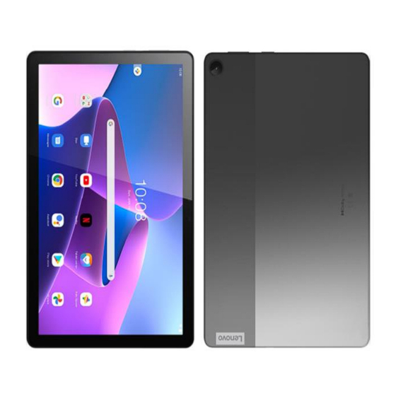
Lenovo Tab M10 Gen3 Level 2 – Service and Repair Manual NTRODUCTION External Views Figure 1. External Views Lenovo Confidential Restricted: Page 6 / 72 Do not share without consent from Lenovo... - Page 8 Table 1. External Views Parts List Reference # Description Power Key Volume Key Loudspeaker Audio Jack USB Type C Card Tray Display Screen Middle Frame Rear Cover Rear-Facing Camera Front-Facing Camera Lenovo Confidential Restricted: Page 7 / 72 Do not share without consent from Lenovo...
-
Page 9: Main Exploded Views
Lenovo Tab M10 Gen3 Level 2 – Service and Repair Manual Main Exploded Views Figure 2. Assembly Exploded View Lenovo Confidential Restricted: Page 8 / 72 Do not share without consent from Lenovo... - Page 10 TB328 Batt Pull Tape&*CL5420AA001509 CS TB328 TP Adhesive&*CL5420AA001512 CS TB328 LCD ZIF mylar&*CL5480AA000578 CS TB328 Front cam mylar&*CL5480AA000579 CS TB328 LCD FPC cloth&*CL5450AA001159 CS TB328 Waterproof label&*CL7015AA001336CS Lenovo Confidential Restricted: Page 9 / 72 Do not share without consent from Lenovo...
-
Page 11: Disassembly And Recovery
Light Front- Middle Speaker Speaker Sensor Facing Frame Grommet Imager Rear Volume Sub Board Power Key Battery Facing Metal Imager Main Sub Board Main FPC Board Lenovo Confidential Restricted: Page 10 / 72 Do not share without consent from Lenovo... - Page 12 Tools Required for Disassembly Description Part # Picture/Drawing 7″ x 7″ Hot Plate SIM/SD Tray Removal Tool 4-00-U2-10000 Blackstick JCIS #0 Bit Torque Driver (Adjustable) Shim Tweezers Lenovo Confidential Restricted: Page 11 / 72 Do not share without consent from Lenovo...
- Page 13 Lenovo Tab M10 Gen3 Level 2 – Service and Repair Manual Suction Cup Lenovo Confidential Restricted: Page 12 / 72 Do not share without consent from Lenovo...
-
Page 14: Sim Tray Removal
SIM/SD Tray hole until the SIM/SD Tray ejects from the tablet Remove the SIM/SD Tray from the tablet NOTE The SIM/SD Tray can be recovered and reused after removal. Lenovo Confidential Restricted: Page 13 / 72 Do not share without consent from Lenovo... -
Page 15: Sn Label Removal
Use the Tweezers to peel the SN Label from the SIM/SD Tray NOTE Remove the SN Label only if necessary. After you remove it, you cannot reuse it. Lenovo Confidential Restricted: Page 14 / 72 Do not share without consent from Lenovo... -
Page 16: Display Removal
Remove the Tablet from the platform. // CAUTION // Wear protective gloves when handling heated Tablet. NOTE Perform the Display removal procedure before the Tablet starts to cool off. Lenovo Confidential Restricted: Page 15 / 72 Do not share without consent from Lenovo... - Page 17 Care while doing this step do not open the display to avoid damage LCM FPC NOTE If needed, reheat the tablet for no more than 5 min and repeat. Lenovo Confidential Restricted: Page 16 / 72 Do not share without consent from Lenovo...
- Page 18 Use the flat end of the Black stick to disengage the Battery BtB Connector from the Main PCB. 10. Use your fingers to remove the Display Lenovo Confidential Restricted: Page 17 / 72 Do not share without consent from Lenovo...
-
Page 19: Lcm Fpc Removal
ZIF connector and remove the LCM FPC by the handle NOTE The LCM FPC can be recovered and reused after removal. Use your fingers remove the LCM FPC by handle as shown Lenovo Confidential Restricted: Page 18 / 72 Do not share without consent from Lenovo... -
Page 20: Battery Connector Steel Removal
The Battery Connector steel can be recovered and reused after removal. Use the flat end of the Black stick to disengage Battery BtB connector from the Main board as shown Lenovo Confidential Restricted: Page 19 / 72 Do not share without consent from Lenovo... -
Page 21: Middle Frame Removal
Use finger remove the Middle frame NOTE The Middle Frame can be recovered and reused after removal. Lenovo Confidential Restricted: Page 20 / 72 Do not share without consent from Lenovo... -
Page 22: Side Key Fpc Removal
Side Key FPC from the location as shown. NOTE Remove the Side Key FPC only if necessary. After you remove it, you cannot reuse it. Lenovo Confidential Restricted: Page 21 / 72 Do not share without consent from Lenovo... -
Page 23: Front-Facing Imager Removal
Front-Facing Imager BtB Connector from the Main Board. Use the Tweezers to remove the Front-Facing Imager from the tablet. NOTE The Front-Facing Imager can be recovered and reused after removal. Lenovo Confidential Restricted: Page 22 / 72 Do not share without consent from Lenovo... -
Page 24: Left Speaker Removal
Use the flat end of the Black stick to disengage the Left Speaker on Right up conner, remove the Left Speaker by your fingers NOTE The Left Speaker can be recovered and reused after removal. Lenovo Confidential Restricted: Page 23 / 72 Do not share without consent from Lenovo... -
Page 25: Right Speaker Removal
Use the flat end of the Black stick to disengage the Left Speaker on left side, remove the Left Speaker by your fingers. NOTE The Right Speaker can be recovered and reused after removal. Lenovo Confidential Restricted: Page 24 / 72 Do not share without consent from Lenovo... -
Page 26: Light Sensor Grommet Removal
Use the Tweezers to remove the Light Sensor Grommet from the Main board as shown NOTE The Proximity Sensor Grommet can be recovered and reused after removal. Lenovo Confidential Restricted: Page 25 / 72 Do not share without consent from Lenovo... -
Page 27: Rear-Facing Imager Removal
Rear-Facing Imager BtB Connector from the Main Board. Use the Tweezers to remove the Rear-Facing Imager from the Tablet. NOTE The Rear-Facing Imager can be recovered and reused after removal. Lenovo Confidential Restricted: Page 26 / 72 Do not share without consent from Lenovo... -
Page 28: Main Board Removal
Board as shown Use your fingers to remove the Main Board from the Rear Cover as shown NOTE The Main Board can be recovered and reused after removal. Lenovo Confidential Restricted: Page 27 / 72 Do not share without consent from Lenovo... -
Page 29: Usb Board Steel Removal
Board Steel. Use the Tweezers to remove the USB Board Steel from the tablet. NOTE The USB Board Steel can be recovered and reused after removal. Lenovo Confidential Restricted: Page 28 / 72 Do not share without consent from Lenovo... -
Page 30: Main Fpc Removal
Main FPC BtB Connector from the USB Board. Use your fingers to remove the Main FPC from the tablet. NOTE The Main FPC can be recovered and reused after removal. Lenovo Confidential Restricted: Page 29 / 72 Do not share without consent from Lenovo... -
Page 31: Usb Board Removal
1 Green Screws from the USB Board. Use your fingers to remove the USB Board from the Rear Cover. NOTE The USB Board can be recovered and reused after removal. Lenovo Confidential Restricted: Page 30 / 72 Do not share without consent from Lenovo... -
Page 32: Battery Removal
Battery are free of foreign material. Ensure screws and screwdrivers do not contact the Battery. Lenovo Confidential Restricted: Page 31 / 72 Do not share without consent from Lenovo... -
Page 33: Volume Key Removal
Volume Keys from the Rear Cover Use the Tweezers to remove the Volume Keys from the Rear Cover NOTE The Volume Key can be recovered and reused after removal. Lenovo Confidential Restricted: Page 32 / 72 Do not share without consent from Lenovo... -
Page 34: Power Key Removal
Power Keys from the Rear Cover Use the Tweezers to remove the Power Keys from the Rear Cover NOTE The Power Key can be recovered and reused after removal. Lenovo Confidential Restricted: Page 33 / 72 Do not share without consent from Lenovo... -
Page 35: Parts Refresh
Level 2 – Service and Repair Manual ARTS EFRESH Description Part # Picture/Drawing Black stick ESD Mat and Wrist Strap Gloves or Finger Collets Isopropyl (ISP) Alcohol Cleaning Pads Lenovo Confidential Restricted: Page 34 / 72 Do not share without consent from Lenovo... -
Page 36: Middle Frame Cleaning
Middle Cover as shown. /// CAUTION /// Remove the adhesive carefully to avoid damage to the Middle Frame. Lenovo Confidential Restricted: Page 35 / 72 Do not share without consent from Lenovo... -
Page 37: Assembly
Left USB Board Sensor Facing Speaker Speaker Metal Grommet Imager Battery Volume Power Key Connector Battery Metal Side Key Middle Frame SD Tray LDM FPC Display Lenovo Confidential Restricted: Page 36 / 72 Do not share without consent from Lenovo... -
Page 38: Tools Required For Assembly
Lenovo Tab M10 Gen3 Level 2 – Service and Repair Manual Tools Required for Assembly The following tools are required to assemble the Lenovo Tab M10 Gen3 tablet Description Part # Picture/Drawing Black stick JCIS #0 Bit Torque Driver (Adjustable) -
Page 39: Water Detection Label Assembly
Use the Tweezers to place the WDL onto the USB Board in the location shown Use the Tweezers to place the WDL onto the USB Board in the location shown Lenovo Confidential Restricted: Page 38 / 72 Do not share without consent from Lenovo... -
Page 40: Main Board Assembly
Use your fingers to place the Main Board into the pocket of the Rear Cover as shown. Check the Main Board in right Position as shown Lenovo Confidential Restricted: Page 39 / 72 Do not share without consent from Lenovo... -
Page 41: Usb Board Assembly
Use your fingers to place the Main PCB into the pocket of the Rear Cover as shown Check the USB Board in right Position as shown Lenovo Confidential Restricted: Page 40 / 72 Do not share without consent from Lenovo... -
Page 42: Main Fpc Assembly
The Main FPC print “Main” side connect to the Main Board Use your fingers to place and secure the Main FPC BtB Connector on the USB Board as shown Lenovo Confidential Restricted: Page 41 / 72 Do not share without consent from Lenovo... -
Page 43: Usb Board Steel Assembly
Check the USB Board Steel position aligning with the pins as shown. Use the Torque Driver and JCIS #0 Bit to tighten the 2 Green Screws to 0.80±0.06 Kgf/cm. Lenovo Confidential Restricted: Page 42 / 72 Do not share without consent from Lenovo... -
Page 44: Rear-Facing Camera Assembly
Facing Camera on the location as shown Use your fingers to place and secure the Rear- Facing Camera FPC BtB Connector on the Main board as shown. Lenovo Confidential Restricted: Page 43 / 72 Do not share without consent from Lenovo... -
Page 45: Left Speaker Assembly
TB328 Speaker box_L&*CL5016AA000262 CS Use your fingers to place Left Speaker Box on the Rear Cover as shown. Check the Left Speaker position aligning with the pins as shown. Lenovo Confidential Restricted: Page 44 / 72 Do not share without consent from Lenovo... -
Page 46: Right Speaker Assembly
Check the Left Speaker position aligning with the pins as shown. Use the Torque Driver and JCIS #0 Bit to tighten the 12 Green Screws to 0.80±0.06 Kgf/cm. as shown Lenovo Confidential Restricted: Page 45 / 72 Do not share without consent from Lenovo... -
Page 47: Light Sensor Grommet Assembly
Use the Tweezer to place the Light Sensor Grommet on the location as shown. NOTE Light Sensor Rubber has directional requirement, the white film on the left. Lenovo Confidential Restricted: Page 46 / 72 Do not share without consent from Lenovo... -
Page 48: Front-Facing Imager Assembly
Slide a fingertip across the ZIF Connector Door to close it. Use fingers to place and secure the Front-Facing Camera on the location as shown. Lenovo Confidential Restricted: Page 47 / 72 Do not share without consent from Lenovo... - Page 49 Use the Tweezers to place the Mylar over the Front-Facing Camera ZIF Connector Door as Shown. Use the Tweezers to place the Front-Facing Rubber on the Front-Facing Camera as Shown. Lenovo Confidential Restricted: Page 48 / 72 Do not share without consent from Lenovo...
-
Page 50: Battery Assembly
Battery are free of foreign material. Ensure screws and screwdrivers do not contact the Battery. Use the Tweezers to remove First Battery Adhesive from the liner. Lenovo Confidential Restricted: Page 49 / 72 Do not share without consent from Lenovo... - Page 51 Use the Tweezers to remove the lining of the Battery Adhesive. Use your fingers to place the Battery into the pocket of the Rear Housing. Lenovo Confidential Restricted: Page 50 / 72 Do not share without consent from Lenovo...
- Page 52 NOTE For each cycle roll the Manual Roller from top to bottom of the Battery and vice versa. NOTE Each cycle should last for 3 seconds. Lenovo Confidential Restricted: Page 51 / 72 Do not share without consent from Lenovo...
-
Page 53: Battery Connector Metal Assembly
Connector Metal over the Lower PCB as shown. Use the Torque Driver and JCIS #0 Bit to tighten the 2 Green Screws to 0.80±0.06 as shown Lenovo Confidential Restricted: Page 52 / 72 Do not share without consent from Lenovo... -
Page 54: Power Key Assembly
Use the Tweezers to press the Power Keys into the pocket of the Rear Cover as shown. Use the Tweezers to put the key rubber in the right hook as shown Lenovo Confidential Restricted: Page 53 / 72 Do not share without consent from Lenovo... -
Page 55: Power Key Assembly
Use the Tweezers to press the Volume Keys into the pocket of the Rear Cover as shown Check the Key Rubber position aligning with the pins as shown. Lenovo Confidential Restricted: Page 54 / 72 Do not share without consent from Lenovo... -
Page 56: Side Key Fpc Assembly
Use fingers to place and secure the Side Key FPC on the location aligning with the pins as shown. NOTE Press firmly for seconds 3 times to activate the adhesive. Lenovo Confidential Restricted: Page 55 / 72 Do not share without consent from Lenovo... -
Page 57: Tp Adhesive Assembly
Align TP Adhesive from the narrow side of Middle Frame, make sure the adhesive is attached to the support surface, no climb wall and no overhang Lenovo Confidential Restricted: Page 56 / 72 Do not share without consent from Lenovo... -
Page 58: Middle Frame Assembly
ZIF Connector Door of Side key FPC Slide the Side Key FPC into the ZIF Connector Door, using the white line as a guide for insertion depth. Lenovo Confidential Restricted: Page 57 / 72 Do not share without consent from Lenovo... - Page 59 4 Green Screws to 0.80±0.06 Kgf/cm as shown Use the Torque Driver and JCIS #0 Bit to tighten the 7 Sliver Screws to 0.80±0.06 Kgf/cm as shown Lenovo Confidential Restricted: Page 58 / 72 Do not share without consent from Lenovo...
-
Page 60: Lcd Fpc Assembly
Door, using the white line as a guide for insertion depth. Use the pointed end of the Black Stick to close the ZIF Connector Door as shown Lenovo Confidential Restricted: Page 59 / 72 Do not share without consent from Lenovo... - Page 61 Use the Tweezers to place the LCD FPC Cloth on the display as shown. NOTE Press firmly for seconds 3 times to activate the adhesive. Lenovo Confidential Restricted: Page 60 / 72 Do not share without consent from Lenovo...
-
Page 62: Display Assembly
Use your finger pressure to connect the LCM FPC BtB Connector to the Main PCB as shown Use the Tweezers to put LCM Connector Metal on Main Board as shown Lenovo Confidential Restricted: Page 61 / 72 Do not share without consent from Lenovo... - Page 63 Use your fingers to remove the red liner of TP Adhesive on top gap as Shown Use fingers to place the Display on the Rear Cover as shown. Lenovo Confidential Restricted: Page 62 / 72 Do not share without consent from Lenovo...
- Page 64 10. Use Weight press the Display Press Fixture, the Pressure 1600±160N, Time 15±1S. 11. Remove the Weight and Display Press Fixture cover, take out the tablet. Lenovo Confidential Restricted: Page 63 / 72 Do not share without consent from Lenovo...
- Page 65 16. Place both thumbs on point 4 and slide them out to point 5. 17. Place both thumbs on point 5 and slide them out to point 6. Lenovo Confidential Restricted: Page 64 / 72 Do not share without consent from Lenovo...
-
Page 66: Sn Label Assembly
Level 2 – Service and Repair Manual SN Label Assembly Description Reference # TB328FU SIM tray_ss&*CL5017AA000796 CS LC7015AA002620+P530 label 75x12+10x1.35 Use the Tweezers to place the SN label onto the SIM/SD Tray. Lenovo Confidential Restricted: Page 65 / 72 Do not share without consent from Lenovo... -
Page 67: Sd Tray Assembly
Reference # TB328 TP+LCM Assy&*24011-00028 CS TB328FU RearCover Assy&*22002-08029 CS TB328FU SIM tray_ss&*CL5017AA000796 CS Use your fingers to push the SD Tray into the SD Tray Slot. Lenovo Confidential Restricted: Page 66 / 72 Do not share without consent from Lenovo... -
Page 68: Assembly Quality Check
Level 2 – Service and Repair Manual Assembly Quality Check Battery Quality Check Check the Battery Adhesive. Seeing residue or dirt means that that Battery cannot be reused. Lenovo Confidential Restricted: Page 67 / 72 Do not share without consent from Lenovo... -
Page 69: Grommets And Connectors Quality Check
Check that the Front-Facing Imager is securely connected to the Main PCB and no sign of damage. Check that Front-Facing Imager Grommet, mylar and Light Sensor Grommet are not missing Lenovo Confidential Restricted: Page 68 / 72 Do not share without consent from Lenovo... - Page 70 BtB Connector on the Main PCB and check 2 Green screw no missing Check that the LCD FPC is securely connected to the TP LCM ASSY Lenovo Confidential Restricted: Page 69 / 72 Do not share without consent from Lenovo...
- Page 71 Main PCB 12. Check that the LCD Conn Metal covers the LCD FPC BtB Connector on the Main PCB and check 1 Green screw no missing Lenovo Confidential Restricted: Page 70 / 72 Do not share without consent from Lenovo...
-
Page 72: Screws Quality Check
Level 2 – Service and Repair Manual Screws Quality Check Check for any missing or unseated screws under the Middle Frame Check for any missing or unseated screws on the Middle Frame Lenovo Confidential Restricted: Page 71 / 72 Do not share without consent from Lenovo...