
Related Manuals for Dell Inspiron 14 7435 2-in-1


Summary of Contents for Dell Inspiron 14 7435 2-in-1
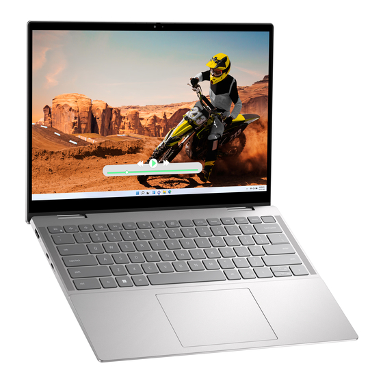
- Page 1 Inspiron 14 7435 2-in-1 Owner's Manual Regulatory Model: P172G Regulatory Type: P172G002 March 2023 Rev. A00...
- Page 2 A WARNING indicates a potential for property damage, personal injury, or death. © 2023 Dell Inc. or its subsidiaries. All rights reserved. Dell Technologies, Dell, and other trademarks are trademarks of Dell Inc. or its subsidiaries. Other trademarks may be trademarks of their respective owners.
-
Page 3: Table Of Contents
Left......................................6 Top......................................7 Front....................................... 8 Bottom....................................9 Service Tag................................... 9 Modes....................................10 Chapter 2: Set up your Inspiron 14 7435 2-in-1................12 Chapter 3: Specifications of Inspiron 14 7435 2-in-1..............14 Dimensions and weight..............................14 Processor..................................... 14 Chipset....................................15 Operating system................................15 Memory.................................... - Page 4 After working inside your computer........................29 BitLocker..................................29 Recommended tools................................. 29 Screw list.....................................29 Major components of Inspiron 14 7435 2-in-1......................30 Chapter 5: Removing and installing Customer Replaceable Units (CRUs)........33 Base cover..................................33 Removing the base cover............................33 Installing the base cover............................35 Solid-state drive.................................37...
- Page 5 Clearing BIOS (System Setup) and System passwords..................84 Chapter 9: Troubleshooting......................85 Handling swollen Lithium-ion batteries........................85 Locate the Service Tag or Express Service Code of your Dell computer ..........85 Dell SupportAssist Pre-boot System Performance Check diagnostics..............86 Running the SupportAssist Pre-Boot System Performance Check..............86 Built-in self-test (BIST)..............................
-
Page 6: Chapter 1: Views Of Inspiron 14 7435 2-In-1
Views of Inspiron 14 7435 2-in-1 Right 1. SD-card slot Reads from and writes to the SD card. The computer supports the following card types: ● Secure Digital (SD) ● Secure Digital High Capacity (SDHC) ● Secure Digital Extended Capacity (SDXC) 2. -
Page 7: Top
If the power button has a fingerprint reader, place your finger on the power button to log in. NOTE: The highlighted area indicates the actual active fingerprint reader area and the image is for illustration purposes only. Views of Inspiron 14 7435 2-in-1... -
Page 8: Front
NOTE: You can customize power-button behavior in Windows. For more information, see Me and My Dell at www.dell.com/support/manuals. 3. Right speaker Provides audio output. 4. Precision touchpad Move your finger on the touchpad to move the mouse pointer. Tap to left-click and two fingers tap to right-click. -
Page 9: Bottom
For more information about cleaning air vents, search for articles in Knowledge Base Resource at www.dell.com/support. Service Tag The service tag is a unique alphanumeric identifier that allows Dell service technicians to identify the hardware components in your computer and access warranty information. Views of Inspiron 14 7435 2-in-1... -
Page 10: Modes
Modes The following modes are applicable for your 2-in-1 computers. Notebook Tablet Views of Inspiron 14 7435 2-in-1... - Page 11 Stand Tent Views of Inspiron 14 7435 2-in-1...
-
Page 12: Chapter 2: Set Up Your Inspiron 14 7435 2-In-1
To conserve battery power, the battery might enter power-saving mode. Connect the power adapter and press the power button to turn on the computer. 2. Finish Windows setup. Follow the on-screen instructions to complete the setup. When setting up, Dell recommends that you: ● Connect to a network for Windows updates. NOTE: If connecting to a secured wireless network, enter the password for the wireless network access when prompted. - Page 13 Dell Digital Delivery Download software applications, which are purchased but not preinstalled on your computer. For more information on using Dell Digital Delivery, search in the Knowledge Base Resource at www.dell.com/support. SupportAssist SupportAssist proactively and predictively identifies hardware and software issues on your computer and automates the engagement process with Dell Technical support.
-
Page 14: Chapter 3: Specifications Of Inspiron 14 7435 2-In-1
Specifications of Inspiron 14 7435 2-in-1 Dimensions and weight The following table lists the height, width, depth, and weight of your Inspiron 14 7435 2-in-1. Table 3. Dimensions and weight Description Values Height: Front height 15.54 mm (0.61 in.) Rear height 17.47 mm (0.68 in.) -
Page 15: Chipset
Chipset The following table lists the details of the chipset supported by your Inspiron 14 7435 2-in-1. Table 5. Chipset Description Values Chipset Barcelo Refresh Processor AMD Ryzen 5 7530U/ 7 7730U DRAM bus width 128-bit Flash EPROM 16 MB... -
Page 16: External Ports
M.2 cards, search in the Knowledge Base Resource at www.dell.com/support. Wireless module The following table lists the Wireless Local Area Network (WLAN) modules supported on your Inspiron 14 7435 2-in-1. Table 9. Wireless module specifications Description Option one... -
Page 17: Audio
Microsoft Windows may not support Microsoft Windows may not support the full Bluetooth 5.3 functionality. the full Bluetooth 5.3 functionality. Audio The following table lists the audio specifications of your Inspiron 14 7435 2-in-1. Table 10. Audio specifications Description Values Audio controller... -
Page 18: Media-Card Reader
Up to 1 TB M.2 2280, Class 40 solid-state drive PCIe NVMe Gen4 x4 Up to 2 TB Media-card reader The following table lists the media cards supported by your Inspiron 14 7435 2-in-1. Table 12. Media-card reader specifications Description Values Media-card type... -
Page 19: Keyboard Shortcuts Of Inspiron 14 7435 2-In-1
Keyboard shortcuts of Inspiron 14 7435 2-in-1 NOTE: Keyboard characters may differ depending on the keyboard language configuration. Keys used for shortcuts remain the same across all language configurations. Some keys on your keyboard have two symbols on them. These keys can be used to type alternate characters or to perform secondary functions. -
Page 20: Camera
Fn + Esc Toggle Fn-key lock Fn + Left Arrow Home Fn + Right Arrow Camera The following table lists the camera specifications of your Inspiron 14 7435 2-in-1. Table 16. Camera specifications Description Values Number of cameras Camera type... -
Page 21: Power Adapter
For more information about touchpad gestures available on Windows, see the Microsoft knowledge base article at support.microsoft.com. Power adapter The following table lists the power adapter specifications of your Inspiron 14 7435 2-in-1. Table 18. Power adapter specifications Description Values... -
Page 22: Display
CAUTION: Dell recommends that you charge the battery regularly for optimal power consumption. If your battery charge is completely depleted, connect the power adapter, turn on your computer, and then restart your computer to reduce the power consumption. -
Page 23: Fingerprint Reader (Optional)
Power consumption (maximum) 3.6 W Anti-glare vs glossy finish Anti-glare Fingerprint reader (optional) The following table lists the fingerprint-reader specifications of your Inspiron 14 7435 2-in-1. NOTE: The fingerprint reader is located on the power button. Table 21. Fingerprint reader specifications Description... -
Page 24: Multiple Display Support Matrix
ComfortView mode can be enabled and configured using the Dell CinemaColor application. ComfortView mode complies with TÜV Rheinland's requirement for low blue light displays. Low blue light: Dell ComfortView software technology reduces harmful blue light emissions to make extended screen time easy on your eyes. - Page 25 ● Look away from your display, and gaze at a distant object at 20 ft (609.60 cm) away for at least 20 seconds during each break. ● Take an extended break for 20 minutes every two hours. Specifications of Inspiron 14 7435 2-in-1...
-
Page 26: Chapter 4: Working Inside Your Computer
You should only perform troubleshooting and repairs as authorized or directed by the Dell technical assistance team. Damage due to servicing that is not authorized by Dell is not covered by your warranty. See the safety instructions that is shipped with the product or at www.dell.com/regulatory_compliance. -
Page 27: Safety Precautions
ESD protection is an increasing concern. Due to the increased density of semiconductors used in recent Dell products, the sensitivity to static damage is now higher than in previous Dell products. For this reason, some previously approved methods of handling parts are no longer applicable. -
Page 28: Esd Field Service Kit
Always place parts in your hand, on the ESD mat, in the system, or inside an anti-static bag. ● Transporting Sensitive Components – When transporting ESD sensitive components such as replacement parts or parts to be returned to Dell, it is critical to place these parts in anti-static bags for safe transport. Working inside your computer... -
Page 29: Transporting Sensitive Components
Transporting sensitive components When transporting ESD sensitive components such as replacement parts or parts to be returned to Dell, it is critical to place these parts in anti-static bags for safe transport. -
Page 30: Major Components Of Inspiron 14 7435 2-In-1
M2.5x4 M2x4 Power-button with M2x3 fingerprint reader USB Type-C bracket M2x4 Touchpad M2x2 M1.6x2.5 System board M2x1.8 Major components of Inspiron 14 7435 2-in-1 The following image shows the major components of Inspiron 14 7435 2-in-1. Working inside your computer... - Page 31 1. Base cover 2. I/O board cable 3. Heat sink 4. USB Type-C bracket 5. System board 6. M.2 2230 solid-state drive 7. Wireless-card bracket 8. Wireless card 9. Touchpad 10. Display assembly 11. Palm-rest and keyboard assembly 12. Battery 13.
- Page 32 NOTE: Dell provides a list of components and their part numbers for the original system configuration purchased. These parts are available according to warranty coverages purchased by the customer. Contact your Dell sales representative for purchase options. Working inside your computer...
-
Page 33: Chapter 5: Removing And Installing Customer Replaceable Units (Crus)
Removing and installing Customer Replaceable Units (CRUs) The replaceable components in this chapter are Customer Replaceable Units (CRUs). CAUTION: Customers can replace only the Customer Replaceable Units (CRUs) following the safety precautions and replacement procedures. NOTE: The images in this document may differ from your computer depending on the configuration you ordered. Base cover Removing the base cover Prerequisites... - Page 34 Removing and installing Customer Replaceable Units (CRUs)
-
Page 35: Installing The Base Cover
Steps 1. Remove the four screws (M2x4) that secure the base cover to the palm-rest and keyboard assembly. 2. Loosen the three captive screws that secure the base cover to the palm-rest and keyboard assembly. NOTE: Upon loosening the captive screws, the base cover will open up creating a gap between the base cover and the palm-rest assembly at the hinges. - Page 36 Removing and installing Customer Replaceable Units (CRUs)
-
Page 37: Solid-State Drive
Steps 1. Connect the battery cable to the connector on the system board and adhere the tape that secures the battery cable to the battery. 2. Align the screw holes on the base cover with the screw holes on the palm-rest and keyboard assembly, and then snap the base cover into place. -
Page 38: Installing The M.2 2230 Solid-State Drive
Steps 1. Remove the screw (M2x3) that secures the M.2 2230 solid-state drive assembly to the system board. 2. Slide and lift the M.2 2230 solid-state drive assembly off the system board. 3. Flip over the M.2 2230 solid-state drive assembly. 4. - Page 39 ● M.2 2230 solid-state drive + M.2 2230 solid-state drive mounting bracket ● M.2 2280 solid-state drive The following image indicates the location of the M.2 2230 solid-state drive and provides a visual representation of the installation procedure. Steps 1. Place and align the M.2 2230 solid-state drive on the M.2 2230 solid-state drive mounting bracket 2.
-
Page 40: Removing The M.2 2280 Solid-State Drive
Removing the M.2 2280 solid-state drive Prerequisites 1. Follow the procedure in Before working inside your computer. 2. Remove the base cover. About this task NOTE: This procedure applies only to computers shipped with an M.2 2280 solid-state drive installed. NOTE: The M.2 card installed on your computer will depend on the configuration ordered. -
Page 41: Wireless Card
● M.2 2230 solid-state drive + M.2 2230 solid-state drive mounting bracket ● M.2 2280 solid-state drive The following image indicates the location of the M.2 2280 solid-state drive and provides a visual representation of the installation procedure. Steps 1. Align the notch on the M.2 2280 solid-state drive with the tab on the M.2 solid-state drive slot on the system board. 2. -
Page 42: Installing The Wireless Card
Steps 1. Remove the screw (M2x3) that secures the wireless-card bracket to the wireless card and system board. 2. Lift the wireless-card bracket off the wireless card. 3. Disconnect the antenna cables from the wireless card. 4. Slide and lift the wireless card off the system board. Installing the wireless card Prerequisites If you are replacing a component, remove the existing component before performing the installation procedure. - Page 43 Steps 1. Connect the antenna cables to the wireless card. The following table provides the antenna-cable color scheme for the wireless card that is supported by your computer. Table 26. Antenna-cable color scheme Connectors on the Antenna-cable color Silkscreen marking wireless card △...
-
Page 44: Fan
2. Follow the procedure in After working inside your computer. Removing the fan Prerequisites 1. Follow the procedure in Before working inside your computer. 2. Remove the base cover. About this task The following image indicates the location of the fan and provides a visual representation of the removal procedure. Steps 1. - Page 45 Steps 1. Place the fan on the palm-rest and keyboard assembly. 2. Align the screw holes on the fan with the screw holes on the palm-rest and keyboard assembly. 3. Remove the two screws (M2x3) that secure the fan to the palm-rest and keyboard assembly. 4.
-
Page 46: Chapter 6: Removing And Installing Field Replaceable Units (Frus)
● If the battery gets stuck inside your computer as a result of swelling, do not try to release it as puncturing, bending, or crushing a lithium-ion battery can be dangerous. In such an instance, contact Dell technical support for assistance. See www.dell.com/contactdell. -
Page 47: Installing The Battery
Prerequisites 1. Follow the procedure in Before working inside your computer. 2. Remove the base cover. About this task The following image indicates the location of the battery and provides a visual representation of the removal procedure. Steps 1. Peel the tape that secures the battery cable to the system board, if applicable. 2. -
Page 48: Coin-Cell Battery
Steps 1. Align the screw holes on the battery with the screw holes on the palm-rest and keyboard assembly. 2. Replace the five screws (M2x3) that secure the battery to the palm-rest and keyboard assembly. 3. Connect the battery cable to the system board. 4. -
Page 49: Installing The Coin-Cell Battery
Steps 1. Disconnect the coin-cell battery from the I/O board. 2. Peel the coin-cell battery and lift it off the slot on the palm-rest and keyboard assembly. Installing the coin-cell battery CAUTION: The information in this section is intended for authorized service technicians only. Prerequisites If you are replacing a component, remove the existing component before performing the installation procedure. -
Page 50: Heat Sink
Steps 1. Adhere the coin-cell battery to the slot on the palm-rest and keyboard assembly. 2. Connect the coin-cell battery cable to the I/O board. Next steps 1. Install the base cover. 2. Follow the procedure in After working inside your computer. -
Page 51: Installing The Heat Sink
Steps 1. In reverse sequential order (4 > 3 > 2 > 1), loosen the four captive screws that secure the heat sink to the system board. 2. Lift the heat sink off the system board. Installing the heat sink CAUTION: The information in this section is intended for authorized service technicians only. -
Page 52: I/O Board
Steps 1. Place the heat sink on the system board. 2. Align the screw holes on the heat sink with the screw holes on the system board. 3. In sequential order (1 > 2 > 3 > 4) tighten the four captive screws that secure the heat sink to the system board. Next steps 1. -
Page 53: Installing The I/O Board
Steps 1. Remove the two screws (M2.5x4) that secure the left display hinge to the palm-rest and keyboard assembly. 2. Pry open the left display hinge to an angle of 90 degrees. 3. Lift the latch and disconnect the power-button with fingerprint reader cable from the I/O board. NOTE: This step is only applicable to computers shipped with the optional fingerprint reader. -
Page 54: Power-Button
Steps 1. Place the I/O board on the palm-rest and keyboard assembly. 2. Align the screw holes on the I/O board with the screw holes on the palm-rest and keyboard assembly. 3. Replace the screw (M2x3) that secure the I/O board to the palm-rest and keyboard assembly. 4. -
Page 55: Installing The Power-Button
2. Remove the base cover. 3. Remove the board. About this task NOTE: This procedure is applicable only for computers that are shipped without the optional fingerprint reader. The following image indicates the location of the power-button and provides a visual representation of the removal procedure. Steps 1. -
Page 56: Power Button With Fingerprint Reader
Steps 1. Place the power-button into its slot on the palm-rest and keyboard assembly. 2. Align the screw hole on the power-button with the screw hole on the palm-rest and keyboard assembly. 3. Replace the screw (M2x3) that secures power-button to the palm-rest and keyboard assembly. Next steps 1. -
Page 57: Installing The Power-Button With Fingerprint Reader
Steps 1. Peel off the mylar covering the fingerprint-reader cable. 2. Remove the screw (M2x3) that secures the power-button with fingerprint reader to the palm-rest and keyboard assembly. 3. Lift the power-button with fingerprint reader, along with the fingerprint-reader cable, off the palm-rest and keyboard assembly. -
Page 58: Touchpad
Steps 1. Align and place the power-button, along with the fingerprint-reader cable, into its slot on the palm-rest and keyboard assembly. 2. Align the screw hole on the power-button with the screw holes on the palm-rest and keyboard assembly. 3. Replace the screw (M2x3) that secures power-button to the palm-rest and keyboard assembly. 4. -
Page 59: Installing The Touchpad
Steps 1. Lift the latch and disconnect the touchpad cable from the system board. 2. Lift the latch and disconnect the touchpad cable from the touchpad. 3. Lift the touchpad cable off the palm-rest and keyboard assembly. 4. Remove the five screws (M1.6x2.5) and the four screws (M2x2) that secure the touchpad to the palm-rest and keyboard assembly. - Page 60 Steps 1. Place the touchpad into its slot on the palm-rest and keyboard assembly. 2. Align the screw holes on the touchpad with the screw holes on the palm-rest and keyboard assembly. 3. Replace the four screws (M2x2) and the five screws (M1.6x2.5) that secure the touchpad to the palm-rest and keyboard assembly.
-
Page 61: Speakers
Speakers Removing the speakers CAUTION: The information in this section is intended for authorized service technicians only. Prerequisites 1. Follow the procedure in Before working inside your computer. 2. Remove the base cover. 3. Remove the battery. 4. Remove the wireless card. -
Page 62: Installing The Speakers
Steps 1. Lift the latch and disconnect the keyboard-backlight cable from the system board. 2. Lift the latch and disconnect the keyboard cable from the system board. 3. Lift the latch and disconnect the touchpad cable from the system board. 4. - Page 63 Steps 1. Using the alignment posts and rubber grommets, place the speakers on the slots of the palm-rest and keyboard assembly. 2. Route the speaker and wireless module cables through the routing guides on the palm-rest and keyboard assembly. 3. Connect the speaker cable to the system board. 4.
-
Page 64: Display Assembly
Display assembly Removing the display assembly CAUTION: The information in this section is intended for authorized service technicians only. Prerequisites 1. Follow the procedure in Before working inside your computer. 2. Remove the base cover. About this task The following image(s) indicate the location of the display assembly and provides a visual representation of the removal procedure. -
Page 65: Installing The Display Assembly
Steps 1. Peel the tape that secures the display-cable connector latch to the system board. 2. Lift the latch and disconnect the display cable from the connector on the system board. 3. Lift the latch and disconnect the touch-screen cable from the connector on the system board. 4. - Page 66 Steps 1. Place the palm-rest and keyboard assembly on a clean and flat surface. Removing and installing Field Replaceable Units (FRUs)
-
Page 67: System Board
2. Place the display assembly on the palm-rest and keyboard assembly. CAUTION: To avoid damaging the display, do not slide the display assembly. 3. Align the screw holes on the left display hinge with the screw holes on the palm-rest and keyboard assembly. 4. - Page 68 1. Touch-screen cable connector 2. Display-cable connector 3. Battery-cable connector 4. Keyboard-backlight cable connector 5. Keyboard-cable connector 6. Touchpad-cable connector 7. Speaker-cable connector 8. M.2 solid-state drive connector 9. M.2 wireless-card connector 10. I/O-board cable connector 11. Fan-cable connector The following images indicate the location of the system board and provides a visual representation of the removal procedure. Removing and installing Field Replaceable Units (FRUs)
- Page 69 Removing and installing Field Replaceable Units (FRUs)
-
Page 70: Installing The System Board
Steps 1. Disconnect the fan cable from the connector on the system board. 2. Disconnect the speaker cable from the connector on the system board. 3. Lift the latch and disconnect the touchpad cable from the system board. 4. Lift the latch and disconnect the keyboard cable from the system board. 5. - Page 71 Removing and installing Field Replaceable Units (FRUs)
-
Page 72: Palm-Rest And Keyboard Assembly
Steps 1. Align the screw holes on the system board with the screw holes on the palm-rest and keyboard assembly. 2. Replace the two screws (M2x1.8) that secure the system board to the palm-rest and keyboard assembly. 3. Lift up the mylar that covers the I/O-board connector on the system board. 4. -
Page 73: Installing The Palm-Rest And Keyboard Assembly
About this task The following image indicates the location of the palm-rest and keyboard assembly and provides a visual representation of the removal procedure. Steps After performing the steps in the pre-requisites, you are left with the palm-rest and keyboard assembly. Installing the palm-rest and keyboard assembly CAUTION: The information in this section is intended for authorized service technicians only. - Page 74 Steps Place the palm-rest and keyboard assembly on a clean and flat surface. Next steps 1. Install the touchpad. 2. Install the system board. NOTE: The system board can be removed with the heat sink attached to avoid breaking the thermal bond between the heat sink and the system board.
-
Page 75: Chapter 7: Software
● Windows 11 Pro National Academic, 64-bit ● Windows 11 Home, 64-bit ● Windows 11 Home in S-mode, 32-bit Drivers and downloads When troubleshooting, downloading or installing drivers it is recommended that you read the Dell Knowledge Based article, Drivers and Downloads FAQ 000123347. Software... -
Page 76: Chapter 8: Bios Setup
BIOS setup CAUTION: Unless you are an expert computer user, do not change the settings in the BIOS Setup program. Certain changes can make your computer work incorrectly. NOTE: Depending on the computer and its installed devices, the items listed in this section may or may not be displayed. NOTE: Before you change BIOS Setup program, it is recommended that you write down the BIOS Setup program screen information for future reference. -
Page 77: System Setup Options
The one-time boot menu displays the devices that you can boot from including the diagnostic option. The boot menu options are: ● HDD1- Windows Boot Manager ● BIOS Setup ● Diagnostics NOTE: Choosing Diagnostics, will display the ePSA diagnostics screen. ●... - Page 78 Table 29. System setup options—Advance menu (continued) Advanced operating system, handles USB devices. USB emulation is always enabled during POST. NOTE: You cannot boot any type of USB device (floppy, hard drive, or memory key) when this option is off. By default, the USB Emulation option is enabled.
- Page 79 By default, the BIOS Auto-Recovery option is disabled. SupportAssist System Resolution Auto OS Recovery Threshold Controls the automatic boot flow for SupportAssist System Resolution Console and for the Dell OS Recovery tool. By default, the Auto OS Recovery Threshold value is set to 2. SupportAssist OS Recovery Enables or disables the boot flow for the SupportAssist OS Recovery tool in the even of certain system errors.
- Page 80 Table 30. System setup options—Security menu (continued) Security By default, Password Change is permitted. Absolute Enables or disables the BIOS module interface of the optional Computer Service from Absolute Software. By default, the Absolute option is disabled. Absolute Status Displays Absolute status. Windows SMM Security Mitigations Table (WSMT) Enables or disables the Windows SMM Security Mitigations Table.
-
Page 81: Updating The Bios
Updating the BIOS Updating the BIOS in Windows Steps 1. Go to www.dell.com/support. 2. Click Product support. In the Search support box, enter the Service Tag of your computer, and then click Search. NOTE: If you do not have the Service Tag, use the SupportAssist feature to automatically identify your computer. You can also use the product ID or manually browse for your computer model. -
Page 82: Updating The Bios From The F12 One-Time Boot Menu
One-Time boot menu on the computer. Most of the Dell computers built after 2012 have this capability, and you can confirm by booting your computer to the F12 One-Time Boot Menu to see if BIOS FLASH UPDATE is listed as a boot option for your computer. If the option is listed, then the BIOS supports this BIOS update option. -
Page 83: Assigning A System Setup Password
NOTE: System and setup password feature is disabled. Assigning a system setup password Prerequisites You can assign a new System or Admin Password only when the status is in Not Set. About this task To enter the system setup, press F12 immediately after a power-on or reboot. Steps 1. -
Page 84: Clearing Cmos Settings
Clearing BIOS (System Setup) and System passwords About this task To clear the system or BIOS passwords, contact Dell technical support as described at www.dell.com/contactdell. NOTE: For information on how to reset Windows or application passwords, refer to the documentation accompanying Windows or your application. -
Page 85: Chapter 9: Troubleshooting
● Using a non-Dell or incompatible battery may increase the risk of fire or explosion. Replace the battery only with a compatible battery purchased from Dell that is designed to work with your Dell computer. Do not use a battery from other computers with your computer. -
Page 86: Dell Supportassist Pre-Boot System Performance Check Diagnostics
Check diagnostics About this task SupportAssist diagnostics (also known as system diagnostics) performs a complete check of your hardware. The Dell SupportAssist Pre-boot System Performance Check diagnostics is embedded with the BIOS and is launched by the BIOS internally. The embedded system diagnostics provides a set of options for particular devices or device groups allowing you to: ●... -
Page 87: Lcd Power Rail Test (L-Bist)
LCD Built-in Self Test (BIST) Dell laptops have a built-in diagnostic tool that helps you determine if the screen abnormality you are experiencing is an inherent problem with the LCD (screen) of the Dell laptop or with the video card (GPU) and PC settings. -
Page 88: System-Diagnostic Lights
3~5 seconds. Non-RPMC Flash on Boot Replace the system board. Guard fused system CPU failure ● Run the Dell Support Assist/Dell Diagnostics tool. ● If problem persists, replace the system board. System board failure (included ●... - Page 89 3~5 seconds to ensure all power are drained. ● Run "BIOS recovery from USB", and the instructions are in the website Dell support. ● If problem persists, replace the system board. Troubleshooting...
-
Page 90: Recovering The Operating System
It enables you to diagnose hardware issues, repair your computer, back up your files, or restore your computer to its factory state. You can also download it from the Dell Support website to troubleshoot and fix your computer when it fails to boot into their primary operating system due to software or hardware failures. -
Page 91: Drain Residual Flea Power (Perform Hard Reset)
6. Install the battery. 7. Install the base cover. 8. Connect the power adapter to your computer. 9. Turn on your computer. NOTE: For more information about performing a hard reset, search in the Knowledge Base Resource at www.dell.com/ support. Troubleshooting... -
Page 92: Chapter 10: Getting Help And Contacting Dell
Getting help and contacting Dell Self-help resources You can get information and help on Dell products and services using these self-help resources: Table 35. Self-help resources Self-help resources Resource location Information about Dell products and services www.dell.com My Dell app...