Table of Contents
Advertisement
Quick Links
[1]
Precaution For Using Lead-Free Solder ....... 1-1
[2]
Safety Precaution For Service Manual.......... 1-2
[3]
Voltage Selection .......................................... 1-2
[4]
AC Plug Adaptor ........................................... 1-2
[5]
Specifications ................................................ 1-3
[6]
Names Of Parts............................................. 1-4
[1]
Tuner Section ................................................ 2-1
[2]
Mechanism Section....................................... 2-2
[1]
Block Diagram............................................... 3-1
[1]
Waveforms Of CD Servo Circuit ....................4-1
[2]
IC Voltage ......................................................4-3
Parts marked with "
" are important for maintaining the safety of the set. Be sure to replace these parts with specified ones
!
for maintaining the safety and performance of the set.
SERVICE MANUAL
PORTABLE CD STEREO SYSTEM
MODEL
In the Interests of user-safety the set should be restored to
its original condition and only parts identical to those
specified be used.
CONTENTS
[1]
Notes On Schematic Diagram .......................5-1
[2]
Types Of Transistor And LED ........................5-1
[3]
Schematic Diagram .......................................5-2
[4]
Wiring Side Of PWB ....................................5-12
[1]
Troubleshooting .............................................6-1
[1]
Function Table Of IC ......................................7-1
[2]
LCD Display.................................................7-10
This document has been published to be used
for after sales service only.
The contents are subject to change without notice.
- 1
QT-MP3W
No. S9632QTMP3W//
QT-MP3W
Advertisement
Table of Contents

Related Manuals for Sharp QT-MP3W


Summary of Contents for Sharp QT-MP3W
-
Page 1: Table Of Contents
QT-MP3W SERVICE MANUAL No. S9632QTMP3W// PORTABLE CD STEREO SYSTEM QT-MP3W MODEL In the Interests of user-safety the set should be restored to its original condition and only parts identical to those specified be used. CONTENTS CHAPTER 1. GENERAL DESCRIPTION CHAPTER 5. CIRCUIT SCHEMATICS AND PARTS Precaution For Using Lead-Free Solder .. -
Page 2: Chapter 1. General Description
QT-MP3W CHAPTER 1. GENERAL DESCRIPTION Audio XL-MP150 Service Manual XLMP150 Market [1] Precautions For Using Lead-Free Solder 1. Employing lead-free solder "AUDIO, CONTROL, RECTIFIER, CD, TUNER, TAPE PWB" of this model employs lead-free solder. The LF symbol indicates lead-free solder, and is attached on the PWB and service manuals. The alphabetical character following LF shows the type of lead-free solder. -
Page 3: Safety Precaution For Service Manual
QT-MP3W [2] Safety Precaution For Service Manual Precaution to be taken when replacing and servicing the Laser Pickup. [3] Voltage Selection [4] AC Power Supply Cord and AC Plug Adaptor 92L15911022019 92L15124023002 1 – 2... -
Page 4: Specifications
FOR A COMPLETE DESCRIPTION OF THE OPERATION OF THIS UNIT, PLEASE REFER TO THE OPERATION MANUAL. As part of our policy of continuous improvement, SHARP reserves the right to make design and specifcation changes for product improvement without prior notice. The performance specification figures indicated are nominal values of production units .There maybe some deviations from these... -
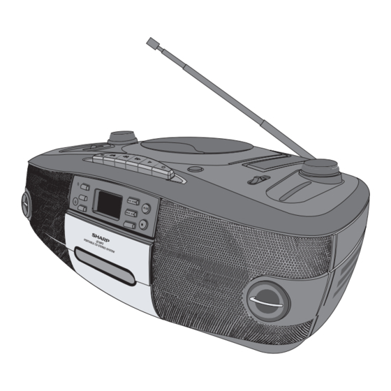
Page 5: Names Of Parts
QT-MP3W [6] Names Of Parts Front panel 3 4 5 6 7 8 9 10 11 1. Cassette Compartment 2. FM Stereo Indicator 3. Folder Down Button 4. Power on Indicator 5. Folder Up Button 6. Memory Button 7. Repeat/Random Button 8. -
Page 6: Chapter 2. Adjustments
QT-MP3W CHAPTER 2. ADJUSTMENTS [1] Tuner Section Use a plastic screw driver for adjustments. Adjust the intermediate frequency of AM and FM to the frequency of ceramic filter. Set of unit Supply voltage DC 12.0V speaker impedance 4ohms L101 T103... -
Page 7: Mechanism Section
QT-MP3W [2] Mechanism Section 1 HEAD AZIMUTH ADJUSTMET ( 1 ) Load the test tape TCC-182A 8KHz for azimuth adjustment. ( 2 ) Press the PLAY button. ( 3 ) Use a cross-tip screwdriver to turn the screw for azimuth adjustment so that the left and right output are maximized. - Page 8 QT-MP3W HEAD AZIMUTH ADJUSTING SCREW Tape recorder section Measurement Adjusting Standard Measurement method Items conditions positions Values :Test tape 1 Playback the test tape TCC-182A (8KHz) Maximum Adjust the head Confirmation left and right output levers become output azimuth screw...
- Page 9 QT-MP3W Electrical Performance Standard Adjusting Measurement Items conditions positions Values :Mode Adjustment of 1 With the recording and playback TDK-D60 recording bias Playback mode mechanism, load the test tapes current Recording mode TDK-D60, and set the mechanism to the +/-0.5 A (Reference recording and pausing condition in advance.
-
Page 10: Chapter 3. Block Diagram
QT-MP3W CHAPTER 3. BLOCK DIAGRAM Figure 1: BLOCK DIAGRAM (1/2) 3 – 1... - Page 11 QT-MP3W Figure 2: BLOCK DIAGRAM (2/2) 3 – 2...
-
Page 12: Chapter 4. Circuit Description
QT-MP3W CHAPTER 4. CIRCUIT DESCRIPTION [1] Waveforms Of CD Servo Circuit CH 4 MEASURE 20µs/div Mode 500ms/div Display < Z1 : 2.5M > < Z1 :1 00K > Position Item Setup -0.20div Coupling IC902 19 IC901 24 Delay Setup DC1M... - Page 13 QT-MP3W < Z1 : 2.5M > 500ms/div IC901 31 IC901 33 Freq (C1) IC901 32 31.25000kHz P1sN (C4) 1133 FR-A (C4) 5.891783kHz IC901 43 CH1 10:1 CH2 10:1 CH3 10:1 CH4 10:1 Edge CH4 5.00 V/div 2.00 V/div 2.00 V/div 2.00 V/div...
-
Page 14: Ic Voltage
QT-MP3W [2] IC Voltage IC904 IC901 IC902 IC903 TC94A34FG TA2157FNG TC94A58FAG MM1669A VOLTAGE VOLTAGE VOLTAGE VOLTAGE VOLTAGE NO VOLTAGE 1.35 0.00 3.20 1.64 1.65 3.54 3.20 0.00 1.65 1.64 1.65 3.56 0.00 0.00 1.65 0.00 1.65 1.65 0.00 0.00 1.65 3.14... -
Page 15: Chapter 5. Circuit Schematics And Parts Layout
QT-MP3W5 CHAPTER 5. CIRCUIT SCHEMATICS AND PARTS LAYOUT [1] Notes On Schematic Diagram • Resistor: • The indicated voltage in each section is the one To differentiate the units of resistors, such symbol as measured by Digital Multimeter between such a K and M are used: the symbol K means 1000 ohm section and the chassis with no signal given. -
Page 16: Schematic Diagram
QT-MP3W [3] Schematic Diagram Figure 5-1: TUNER SCHEMATIC DIAGRAM 5 – 2... - Page 17 QT-MP3W Figure 5-2: DISPLAY SCHEMATIC DIAGRAM 5 – 3...
- Page 18 QT-MP3W Figure 5-3: AUDIO SCHEMATIC DIAGRAM 5 – 4...
- Page 19 QT-MP3W Figure 5-4: TAPE SCHEMATIC DIAGRAM 5 – 5...
- Page 20 QT-MP3W Figure 5-5: POWER SCHEMATIC DIAGRAM 5 – 6...
- Page 21 QT-MP3W -MEMO- 5 – 7...
- Page 22 QT-MP3W Figure 5-6: CD SCHEMATIC DIAGRAM (1/4) 5 – 8...
- Page 23 QT-MP3W Figure 5-7: CD SCHEMATIC DIAGRAM (2/4) 5 – 9...
- Page 24 QT-MP3W Figure 5-8: CD SCHEMATIC DIAGRAM (3/4) 5 – 10...
- Page 25 QT-MP3W Figure 5-9: CD SCHEMATIC DIAGRAM (4/4) 5 – 11...
-
Page 26: Wiring Side Of Pwb
QT-MP3W55 [4] Wiring Side Of PWB FROM SPEAKER UNIT AUDIO PWB-A1 COLOR TABLE GRAY ORANGE WIR 1 BROWN BLACK WHITE B C E CNS702 FROM CONTROL PWB-A2 CN702 Figure 5-10: WIRING SIDE OF AUDIO PWB (TOP VIEW) (1/2) – 12... - Page 27 QT-MP3W CORE CD PWB-B CN902 1 2 3 4 5 6 7 WIR 1 B C E B C E 6 5 4 3 2 1 1 2 3 4 5 6 7 8 9 10 B C E 1 2 3 4 5 6 7 8 9 10...
- Page 28 QT-MP3W CONTROL PWB-A2 AUDIO PWB-A1 CN202 COLOR TABLE ORANGE GRAY FFC703 Figure 5-12: WIRING SIDE OF CONTROL PWB 5 – 14...
- Page 29 QT-MP3W -MEMO- 5 – 15...
- Page 30 QT-MP3W RECTIFIER PWB-A3 FROM AC POWER SOURCE (VS1) & BATTERY TERMINAL COLOR TABLE BLACK ORANGE WHITE GRAY YELLOW Figure 5-13: WIRING SIDE OF RECTIFIER PWB (1/2) 5 – 16...
- Page 31 QT-MP3W BL BR RD VOLTAGE 12 V Figure 5-14: WIRING SIDE OF RECTIFIER PWB (2/2) 5 – 17...
- Page 32 QT-MP3W TUNER PWB-A4 BAR ANTENNA BAR ANTENNA Figure 5-15: WIRING SIDE OF TUNER PWB (TOP VIEW) (1/2) 5 – 18...
- Page 33 QT-MP3W BAR ANTENNA BAR ANTENNA 22 21 20 19 18 17 16 15 14 13 1 2 3 4 5 6 7 8 9 10 11 12 CNS102 COLOR TABLE GRAY ORANGE FROM GREEN AUDIO PWB-A1 BLACK CN102 WHITE Figure 5-16: WIRING SIDE OF TUNER PWB (TOP VIEW) (2/2)
- Page 34 QT-MP3W TUNER PWB-A4 Figure 5-17: WIRING SIDE OF TUNER PWB (BOTTOM VIEW) (1/2) 5 – 20...
- Page 35 QT-MP3W BAR ANTENNA COLOR TABLE WHITE WH RD BK GR BLACK GREEN TUNER PWB-A4 (Please see at top side page 6-20 & 6-21) LUG 1 ROD ANTENNA Figure 5-18: WIRING SIDE OF TUNER PWB (BOTTOM VIEW) (2/2) 5 – 21...
- Page 36 QT-MP3W CD PWB-B COLOR TABLE BROWN GRAY ORANGE FROM CD DOOR LEAF SWITCH 2 4 6 8 10 12 14 16 1 3 5 7 9 11 13 15 FROM CONTROL PWB-A2 Figure 5-19: WIRING SIDE OF CD PWB (TOP VIEW) (1/2)
- Page 37 QT-MP3W FROM CD PICK-UP UNIT 1 2 3 4 5 6 1 2 3 4 5 6 CNS901 FROM AUDIO PWB-A1 CN901 Figure 5-20: WIRING SIDE OF CD PWB (TOP VIEW) (2/2) 5 – 23...
- Page 38 QT-MP3W CD PWB-B Figure 5-21: WIRING SIDE OF CD PWB (BOTTOM VIEW) (1/2) 5 – 24...
- Page 39 QT-MP3W Figure 5-22: WIRING SIDE OF CD PWB (BOTTOM VIEW) (2/2) 5 – 25...
- Page 40 QT-MP3W TAPE PWB-C Lead-free solder indication Lead-free solder is used in the TAPE PWB. Refer to "Precautions for handling lead-free solder" for instructions and precautions. Figure 5-23: WIRING SIDE OF TAPE PWB (TOP VIEW) (1/2) 5 – 26...
- Page 41 QT-MP3W COLOR TABLE BLACK WHITE ORANGE YELLOW GRAY Figure 5-24: WIRING SIDE OF TAPE PWB (TOP VIEW) (2/2) 5 – 27...
- Page 42 QT-MP3W TAPE PWB-C Figure 5-25: WIRING SIDE OF TAPE PWB (BOTTOM VIEW) (1/2) 5 – 28...
- Page 43 QT-MP3W Figure 5-26: WIRING SIDE OF TAPE PWB (BOTTOM VIEW) (2/2) 5 – 29...
- Page 44 QT-MP3W TAPE PWB-C TAPE PLAY CN203 SWITCH TAPE MECHANISM TAPE MOTOR TAPE PWB-C CN201 CAPACITOR (220 µF/25 V) COLOR TABLE BLACK WHITE YELLOW BLUE Figure 5-27: WIRING SIDE OF TAPE MECHANISM 5 – 30...
- Page 45 QT-MP3W SPEAKER R-CH L-CH AUDIO PWB-A1 CN301 TWEETER TWEETER WOOFER WOOFER COLOR TABLE BLACK BROWN Figure 5-28: WIRING SIDE OF SPEAKER 5 – 31...
-
Page 46: Chapter 6. Flowchart
QT-MP3W CHAPTER 6. FLOWCHART [1] Troubleshooting 1. When the CD does not function The CD section may not operate when the objective lens of the optical pickup is dirty. Clean the objective lens, and check the playback operation. When this section does not operate even after the above step is taken, check the follow- ing items. - Page 47 QT-MP3W SC9641 reposit to 600MS Confirm SLDGE CH 4 Check SLED output and 500ms/div Display < Z1 : 2.5M > reposit or not? drive circuit, see Figure 1 Position -0.20div Coupling U902 19 DC1M Probe 10:1 Offset 0:32 V Start playback without Disc...
- Page 48 QT-MP3W Whether RF wave- Check circuit of SA9618 of form is ok (ftgure4) U901 12 ˜ 0.2v A>0.2µs Check whether disc is good Whether 56pin output raise any high voltage impulse or Confirm output whether have noise or wrong song...
-
Page 49: Chapter 7. Others
QT-MP3W CHAPTER 7. OTHERS [1] Function Table Of IC U712 92L31012161601 : SDRAM (M12L161A) DQ15 DQ14 DQ13 DQ12 DQ11 DQ10 LDQM N.C/RPU UDQM A10/AP Bank Select Data Input Register LDQM 512 x 16 512 x 16 Column Decoder Latency & Burst Length... - Page 50 QT-MP3W U710 92L31000250110 : CPU ( TS2501 ) ( 1/4 ) VSSIO VDD-USB LRCK/GPIO_B22 MODE1 BCLK/GPIO_B21 UT_RX/IDE_nCS/GPIO_59 UT_TX/GPIO_88 nTRST ND_nWE/GPIO_B7 SDO0/GPIO_A0 SCK0/GPIO_A1 SD_CKE/GPIO_B0 SFRM0/GPIO_A2 VSSI SDI0/GPIO_A3 USBH_CN/GPIO_B29 SDO1/GPIO_A4 USBH_DP/GPIO_B28 VDDI USB_DN/GPIO_B27 VSSI USB_DP/GPIO_B26 SCK1/GPIO_A5 nCS3/nOE3/GPIO_B5 Ts2501 VDDIO nCS/nOE2/GPIO_B4 SFRM1/GPIO_A5 nCS1/nOE1/GPIO_B3...
- Page 51 QT-MP3W U710 92L31000250110 : CPU ( TS2501 ) ( 2/4 ) USB_DP/GPIO_B[28], USB_DN/GPIO_B[27] USBH_DP/GPIO_B[28], USBH_DN/GPIO_B[29] XIN, XOUT Pll & USB1.1 XTIN, XTOUT Boot ROM CLK Generator Host/Device XFILT (4KB) TCO2/GPIO_A[11] TCO5/GPIO_A[8] Timers/ TCO1/GPIO_A[7] Counters TCO4/GPIO_A[4] Generation SRAM TCO0/GPIO_A[3] (64KB) DQM[0:1] / XA[21:20]...
- Page 52 QT-MP3W U710 92L31000250110 : CPU ( TS2501 ) ( 3/4 ) PIN DESCRIPTION Signal Name Shared Signal Pin # Type Description-TS2501 External Memory Interface Pins SD_CKE GPIO_B[0] SDRAM Clock Enable signal. Active high. / GPIO_B[0] SD_CLK SDRAM Clock / GPO. SD_CLK can be used as a general purpose output.
- Page 53 QT-MP3W U710 92L31000250110 : CPU ( TS2501 ) ( 4/4 ) Signal Name Shared Signal Pin # Type Description-TS2501 VDD_OSC Digital Power for Oscillators (1.8V) VDDI Digital Power for Internal Core (1.8V) VDDI_ADC Digital Power for ADC (1.8V) VDDA_ADC Analog Power for ADC (3.3V) VDDA_PLL Analog &...
- Page 54 QT-MP3W U711 92L31003980031 : FLASH MEMORY ( SST39VF800A ) V SS DQ15 DQ14 DQ13 DQ12 V DD SST39LF / VF800A DQ11 DQ10 V SS SuperFlash X-Decoder Memory Memory Address Address Buffer & Latches Y-Decoder I/O Buffers and Data Latches Control Logic...
- Page 55 QT-MP3W U901 92L31000964110 : CD SERVO ( SC9641 ) DATA CL16 MCLK_IN SLED DATA_IN VSSP SCLK_IN WCLK_IN SC9641 BCLK MOTO DATA_OUT VDDP SCLK_OUT WCLK_OUT MUTE MODE TRAY_SW SLED_SW CROUT LDON CRIN Servo signal Analog Processor DATA Digital Microcomputer Conversion Connector...
- Page 56 QT-MP3W U902 92L31000925910 : MOTOR DRIVER ( SC9259 ) FIN (GND) 28 27 26 25 24 23 22 21 20 19 18 17 16 15 SA9259 9 10 11 12 13 14 FIN (GND) LEVER CONVERSION LEVER CONVERSION LEVER CONVERSION...
- Page 57 QT-MP3W U903 92L31000961810 : CD RF ( SA9618 ) LDON RFRC VREF VREF VREF VREF VREF VREF VREF RFRC VREF Mode 1.24V LDON 3.4K VREF Figure 7-7 BLOCK DIAGRAM OF IC 7 – 9...
-
Page 58: Lcd Display
QT-MP3W [2] LCD Display DSP701 92L22020382621 GRID ASSIGNMENT OUTER DIMENSIONS PATTERN AREA 7 – 10... -
Page 59: Parts Guide
QT-MP3W PARTS GUIDE PORTABLE CD STEREO SYSTEM QT-MP3W MODEL CONTENTS [8] CAPACITORS [1] INTEGRATED CIRCUITS [9] RESISTORS [2] TRANSISTORS [10] OTHER CIRCUITRY PARTS [3] DIODES [11] CABINET PARTS [4] FILTERS [12] ACCESSORIES/PACKING PARTS [5] TRANSFORMERS [13] P.W.B. ASSEMBLY [6] COILS... - Page 60 QT-MP3W PRICE PART PARTS CODE DESCRIPTION RANK MARK RANK [1] INTEGRATED CIRCUITS IC101 92L21000182400 CSC-1824 IC201 92L21000330800 BA-3308 IC301 92L21000422700 LA-4227 IC501 92L21000405200 TC4052 IC901 92L31000215747 TA2157 IC902 92L31094580600 TC94A58FAG061 IC903 92L31000166968 MM1669XH IC904 92L31094340002 TC94A34FG [2] TRANSISTORS Q101 92L20700901530...
- Page 61 QT-MP3W PRICE PART PARTS CODE DESCRIPTION RANK MARK RANK [7] VIBRATORS/CRYSTALS X901 92L22916934402 CRYSTAL 16.9344MHz X902 92L22916934402 CRYSTAL 16.9344MHz [8] CAPACITORS 92L00406476216 47 UF/16V,Electrolytic [Use in Tuner PWB] 92L30233103150 0.01 UF/50V [Use in CD PWB] 92L00303153850 0.015 UF/50V [Use in Tuner PWB] 92L30233103150 0.01 UF/50V [Use in CD PWB]...
- Page 62 QT-MP3W PRICE PART PARTS CODE DESCRIPTION RANK MARK RANK [8] CAPACITORS C155 92L30232272150 0.0027 UF/50V [Use in CD PWB] C201 92L00502222199 0.0022 UF/100V C202 92L00502102199 0.001 UF/100V C203 92L00417107210 100 UF/10V,Electrolytic C204 92L00425475250 4.7 UF/50V,Electrolytic C205 92L00416106216 10 UF/16V,Electrolytic C206...
- Page 63 QT-MP3W PRICE PART PARTS CODE DESCRIPTION RANK MARK RANK [8] CAPACITORS C915 92L00427107263 100 UF/6.3V,Electrolytic C916 92L00427107263 100 UF/6.3V,Electrolytic C917 92L00406476210 47 UF/10V,Electrolytic C918 92L00406476210 47 UF/10V,Electrolytic C919 92L00427107263 100 UF/6.3V,Electrolytic C920 92L00427107263 100 UF/6.3V,Electrolytic C921 92L00406226210 22 UF/10V,Electrolytic C922...
- Page 64 QT-MP3W PRICE PART PARTS CODE DESCRIPTION RANK MARK RANK [9] RESISTORS R116 92L00101471518 470 OHM 1/8W [Use in Tuner PWB] R117 92L00104104518 100 KOHM 1/8W [Use in Tuner PWB] R117 92L30133103516 10 KOHM 1/16W [Use in CD PWB] R118 92L30133153516...
- Page 65 QT-MP3W PRICE PART PARTS CODE DESCRIPTION RANK MARK RANK [9] RESISTORS R513 92L00102222518 2.2 KOHM 1/8W R514 92L00102102518 1 KOHM 1/8W R701 92L00102682518 6.8 KOHM 1/8W R702 92L00103153518 15 KOHM 1/8W R703 92L00103433518 43 KOHM 1/8W R704 92L00102392518 3.9 KOHM 1/8W...
- Page 66 QT-MP3W PRICE PART PARTS CODE DESCRIPTION RANK MARK RANK [10] OTHER CIRCUITRY PARTS CN701 92L23216019010 Plug, 16 Pins CN702 92L23304120020 Plug, 4 Pins CN901 92L23216019010 Plug, 16 Pins CN902 92L23307120020 Plug, 7 Pins CN903 92L23216019010 Plug, 16 Pins CN904 92L23302120020...
- Page 67 QT-MP3W -MEMO-...
- Page 68 QT-MP3W [11] CABINET PARTS 606 x 4 608 x 2 Voltage Selector PWB-A3 263 x 2 612 x 2 602 x 2 PWB-A1 PWB-E 603 x 3 PWB-B 603 x 4 605 x 3 PWB-C 603 x 6 219 x 2...
- Page 69 QT-MP3W PRICE PART PARTS CODE DESCRIPTION RANK MARK RANK [11] CABINET PARTS 92L5220804XXXX DISPLAY LENS 92L5220450XXXX DISPLAY PANEL 92L5220500XX60 OPERATION/CD/USB/MEMORY/FOLDER KNOB 92L52203200000 LCD BRACKET 92L522041200XX LEFT TWEETER SPEAKER TOP COVER 92L5UH4300030 LEFT ADORN COVER 92L761QUH4GS40 LEFT SPEAKER GRILL 92L76660000000 CASSETTE DOOR SPRING ST1/ST2/ST3...
- Page 70 QT-MP3W PRICE PART PARTS CODE DESCRIPTION RANK MARK RANK [12] ACCESSORIES/PACKING PARTS 92L67627527540 POLY BAG PE 27.5X27.5"x0.04 92L874QUH41210 PULP 92L91TMP312010 PACKING CASE 92L15123023002 AC POWER SUPPLY CORD ( Except Australia ) 92L15124023002 AC POWER SUPPLY CORD ( For Australia Only)
- Page 71 QT-MP3W...
- Page 72 QT-MP3W A0609 SMEF • SCA • STCL • SRSSC...