Panasonic DLP PT-D3500U Operating Instructions Manual
Dlp based projector for commercial use
Hide thumbs
Also See for DLP PT-D3500U:
- Service manual (93 pages) ,
- Brochure & specs (4 pages) ,
- Limited warranty (1 page)

Related Manuals for Panasonic DLP PT-D3500U


Summary of Contents for Panasonic DLP PT-D3500U
-
Page 1: Operating Instructions
Operating Instructions Based Projector Commercial Use PT-D3500U Model No. Read these instructions completely before operating this unit. TQBJ 0178... -
Page 2: Important Safety Notice
This instruction booklet provides all the necessary operating information that you might require. We hope it will help you to get the most performance out of your new product, and that you will be pleased with your Panasonic DLP based projector. - Page 3 For disposal or recycling information please contact your local authorities, or the Electronics Industries Alliance: <http://www.eiae.org.> Declaration of Conformity PT-D3500U Panasonic Matsushita Electric Corporation of America One Panasonic Way, Secaucus, NJ 07094 1-800-524-1448 or 1-800-526-6610 pbtsservice@panasonic.com...
-
Page 4: Table Of Contents
Using the remote control unit ...14 Loading dry cells ...14 Effective range of remote control operation ...14 Setting projector ID number to remote control ...15 Using the remote control as a PC mouse...15 Using a wired remote control...16 Installation ...17 Projection schemes ...17... -
Page 5: Precautions With Regard To Safety
Do not place the projector on top of surfaces which are unstable. • If the projector is placed on top of a surface which is sloped or unstable, it may fall down or tip over, and injury or damage could result. -
Page 6: Caution
• If any water gets inside the projector, contact an Authorized Service Center. Do not insert any foreign objects into the projector. • Do not insert any metal objects or flammable objects into the projector or drop them onto the projector, as doing so can result in fire or electric shocks. -
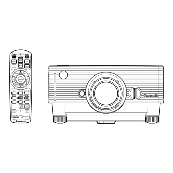
Page 7: Accessories
Ask an Authorized Service Center to clean inside the projector at least once a year. • If dust is left to build up inside the projector without being cleaned out, it can result in fire or problems with operation. • It is a good idea to clean the inside of the projector before the season for humid weather arrives. Ask your nearest Authorized Service Center to clean the projector when required. -
Page 8: Precautions On Handling
Avoid installing the product in a place exposed to vibrations or impacts. If the projector is installed in a place where vibrations are transmitted from a source of driving power and others or mounted in a car or... -
Page 9: Name And Function Of Parts
ID of the remote control. Operation mode selector (Computer/Numeric, Projector) switch (page 15) Put this selector to the right position to control the projector and to the left position to control the PC or use numeric buttons. - Page 10 Moves the mouse cursor. Numeric (0-9) buttons In a system that uses a multiple number of projectors, these buttons serve to specify a particular projector. They are also used to enter the password when the password for service personnel needs to be entered.
-
Page 11: Front And Side Of The Projector
Lens lock button (page 21) Press this to remove the projection lens. Level-adjusting feet (page 22) Use these feet to adjust the tilt of the projector. The leveling feet at the front left and right can be adjusted. Projection lens Lens for projecting images on the screen. -
Page 12: Rear And Side View Of The Main Unit/Controls On Upper Panel
Name and function of parts Rear and side view of the main unit Remote control receiver window (page 14) This also receives the signal beam coming from the remote control. Lamp unit cover The lamp unit is housed. Ventilation holes Clasp for attaching anti-theft chain Attach a chain or other fastening device available from a hardware store through this clamp. -
Page 13: Side-Mounted Connection Terminals
Side-mounted connection terminals LAN terminal (page 38) This terminal is used to control the projector from the PC. (10Base-T/100Base-TX compliant) LAN terminal (10Base-T/100Base-TX) Connect LAN cable. LAN 10/100 lamp (Yellow) Lights up when 100Base-TX connected. LAN LINK/ACT lamp (Green) Lights up when connected. -
Page 14: Using The Remote Control Unit
The remote control should normally be aimed at either the front or rear remote control receiver window on the projector (figure 1). Otherwise, it may also be aimed at the screen, which will reflect commands back to the projector’s front receiver window as illustrated in figure 2. -
Page 15: Setting Projector Id Number To Remote Control
Every projector has its ID number and the ID number of the controlling projector must be set to the remote control in advance so that the user can operate the remote control. The ID number of the projector is set to “ALL”... -
Page 16: Using A Wired Remote Control
Using the remote control unit Using a wired remote control If the installed environment of the main unit is such that an obstacle to the light exists between the main unit and the remote control or the main unit is susceptible to the effects of external light, connect a M3 stereo mini jack cable available in the market to control the main unit. -
Page 17: Installation
Screen Projection distances Listed in the table below are the projection distances of the standard lens provided with the PT-D3500U. Refer to page 61 for the projection distances of the projection lenses available as optional accessories. Screen Size (4 : 3) -
Page 18: Connection
• Before connecting any of your video/audio equipment to the projector, carefully read the owners manual supplied with the equipment once again. • All cable connections should be made with the entire system devices, including the projector, first turned off. • Obtain commercial interconnecting cables for devices supplied with no accessory or optional interconnect cables. -
Page 19: Example Of Connecting With Av Products
• When connecting with a video deck, be sure to use the one with a built-in time base corrector Attention (TBC) or use a TBC between the projector and the video deck. • If nonstandard burst signals are connected, the image may be distorted. If this is the case, connect a TBC between the projector and the video deck. -
Page 20: Example Of Connecting With Pcs
Connection Example of connecting with PCs DVI-D port DVI-D Cable (available in the market) • For the specifications of the RGB signals that can be applied from the PC, see the data sheet on Note page 60. • If your PC has the resume feature (last memory), the computer may not function properly until the resume capability is disabled. -
Page 21: How To Install And Remove The Projection Lens (Optional)
While holding down the lens lock button, turn the lens further counterclockwise. Remove the lens. Lens lock button • Before replacing the lens, turn off the projector’s power. Note • Do not touch the lens signal contact. Dust or dirt may cause defective contact. -
Page 22: Projection
(120 V AC, 50 Hz/60 Hz) Press the “I” marked side of the MAIN POWER switch to turn on the power. The power indicator lights up red, and the projector is placed in the standby mode. Press the POWER button on the main unit, or the POWER ON (|) button on the remote control. -
Page 23: Powering Off The Projector
(Power indicator lit in red) • If you re-power the projector after shutting off the main power inadvertently, the projection lamp may remain unlit. Please turn the power on again after a while. -
Page 24: How To Adjust The Lens
(optical shift) The focus, zoom and up/down position of the images projected on the screen can be adjusted while the projector is positioned appropriately in relation to the screen. Press the LENS button on the remote control or on the control panel of the main unit. -
Page 25: Automatic Adjustment (Auto Setup)
Note Using the SHUTTER function If the projector is not used for a certain period of time during the meeting intermission, for example, a shutter mode is available that allows the user to hide images temporarily. Press the “SHUTTER” button of the remote control or the main unit. -
Page 26: Using The Digital Zoom (- D.zoom +) Function
• The digital zoomed state cannot be stored in memory. Note • If the input signal format is changed while in digital zoom mode, the projector will exit digital zoom function. • The combined magnification of “POSITION” zoom and digital zoom is 9.99 times maximum. -
Page 27: On-Screen Menus
On-screen menus Structure of menu screens Menus are extensively used for configuring, adjusting or reconfiguring the projector. The menus structure is as follows: MENU MENU PICTURE POSITION ADVANCED MENU AUDIO LANGUAGE OPTION1 OPTI0N2 TEST PATTERN SECURITY NETWORK SELECT ENTER EXIT... -
Page 28: Basic Menu Operations
(items). Resetting to the factory default STD (standard) button is used to reset all of the projector adjustment values to the default levels which were set at the time of shipment from the factory. PICTURE... -
Page 29: Adjusting The Picture
Adjusting the picture • For RGB signals • For DVI signals PICTURE PICTURE MODE GRAPHIC PICTURE MODE BRIGHT BRIGHT CONTRAST CONTRAST COLOR TEMP. DEFAULT COLOR TEMP. WHITE GAIN WHITE GAIN SHARPNESS SHARPNESS SYSTEM SELECT SELECT RETRN • For S-Video/Video signals •For YP PICTURE PICTURE MODE... -
Page 30: Sharpness
Adjusting the picture SHARPNESS “SHARPNESS” is used to adjust the crispness of the image. : Sharpens the edge of the image. : Softens the edge of the image. In this mode, the video noise is reduced. (For S-Video/Video/YP OFF : No correction ON : Noise reduction is set to ON. -
Page 31: Adjusting The Position
• Keystone distortion can be corrected to Note ±30° of the angle of tilt for the projector. However, the greater the correction amount, the more the picture quality will deteriorate, and the harder it will become to achieve a good level of focus. To... -
Page 32: How To Use Advanced Menu
How to use ADVANCED MENU ADVANCED MENU DIGITAL CINEMA REALITY BLANKING INPUT RESOLUTION CLAMP POS. RASTER POSITION SXGA MODE SXGA SELSCT ENTER RETRN DIGITAL CINEMA REALITY (Only for input of S-Video/ Video/ YP 576i] signals.) ON: Set at ON when you need to faithfully capture images shot at 24 frames per second as in movies. -
Page 33: Adjusting The Audio
The available languages are: ENGLISH, DEUTSCH, FRANÇAIS, ESPAÑOL, ITALIANO, • The projector’s on-screen display is Note set to the English language by default. Currently chosen language is displayed... -
Page 34: Option1 Settings
SETUP button on the remote control each time signals are input when signals are input frequently such as when the projector is used at a conference. ON : Auto setup is performed automatically when the video signals of the images being projected have changed. -
Page 35: Option2 Settings
• If the projectors are given ID numbers, their remote controls must be assigned the same ID numbers, respectively. • If the ID number of a projector is set to “ALL”, it can be controlled by the remote control or the PC with any ID number. -
Page 36: Fan Control2
VOLUME: You can adjust the sound volume using the menu screen is not displayed. AUTO POW.OFF The projector can be automatically set to the standby mode if no signals are input for the set duration. 3 0 ° PASSWORD 3 0 °... -
Page 37: Displaying The Internal Test Pattern
Displaying the internal test pattern The projector has eight types of internal test patterns to check the condition of the set. To display test patterns, follow the steps below. • Results of adjustment on the image, Note picture quality, position, size and other factors will not be reflected in test patterns. -
Page 38: Setting The Network
Setting the network The settings required for the network must be established in order to use the web browser (page 47) functions that the PC uses to control the projector. NETWORK HOST NAME DHCP IP ADDRESS NET MASK GATEWAY MAC ADDRESS... -
Page 39: Using The Serial Terminals
• Projector ID supported on the RS232C interface is ZZ (ALL) and a group of 1 to 64. • If a command is sent with a projector ID specified, the projector will return answer back only in the following cases: If it coincides with the projector ID, or ID specification is ALL . -
Page 40: Control Commands
Using the serial terminals Control commands When controlling the projector from a computer, the following commands are available: Command Function of command Power “ON” Power “OFF” I I S Switch input modes Shutter function Volume Lamp power setting • If you need a detailed command list, please contact your dealer. -
Page 41: Using The Remote 2 Terminal
Using the REMOTE 2 terminal Using the REMOTE 2 terminal provided on the side of the main unit, it is possible to operate the projector from a control panel etc. furnished in a distant location where infrared remote control signal cannot be received. -
Page 42: Indication Of Lamp Monitor
Indication of lamp monitor This projector is equipped with 2 indicators to show when a lamp needs replacement or there is an abnormal internal temperature. These lamps flash or light up to indicate a problem. Turn the power off and follow the steps below. -
Page 43: Cleaning And Replacement Of Air Filter
If too much dust is deposited in the air filter, temperature inside the main unit will rise and the temperature monitor (TEMP) blinks, eventually turning off the power supply. Clean the air filter section once every 100 hours or so as a guideline depending on the location of projector operation. -
Page 44: Replacing Of Lamp Unit
Replacing the lamp unit WARNING! Replacement of the lamp unit should only be carried out by a qualified technician. Precautions on lamp unit replacement Remove the power plug and confirm that the surroundings of the lamp unit have cooled off. Be careful when handling a light source lamp. -
Page 45: Lamp Unit Replacement Steps
Lamp unit replacement steps • After 1 500 hours (4 000 hours when long life lamp units are used) of operating the same lamp, it Attention is only possible to operate the unit for approximately 10 minutes. Steps completed within 10 minutes. Turn the power off by following the steps on page 23, remove the power plug and confirm that the surroundings of the lamp unit have cooled off. -
Page 46: Replacing The Lamp Unit
Press the “ENTER” button. The SYSTEM INFORMATION screen will be displayed. Press and hold the “ENTER” button on the projector or the remote control for approximately 3 seconds. An item “LAMP TIME RESET” will be added. Press the ENTER button, and when the “LAMP TIME RESET”... -
Page 47: Using Web Browser Control
Using Web Browser Control This projector has networking functions which allow it to be controlled through a web browser on a PC. The controlled items are: • Projector’s settings and adjustment • Projector’s status display • Transmission of a E-mail message when the projector has a problem... -
Page 48: Basic Control Page
Using Web Browser Control Basic control page This page is the first page displayed when the projector is accessed through a web browser. To move from another page, click [Projector control], then [Basic control]. Network set up button Click this item, and a network set up page for IP address and other items appear. -
Page 49: Detail Control Page
Detail control page Click [Projector control], then [Detail control] to display the Detail control page. Pressing these buttons controls the projector and updates the on-screen description on the right of the control page when control is finished. Monitor information page Click [Projector control], then [Status information] to display the Status information page. -
Page 50: Error Information Page
Error information page When is displayed on the status information screen, click it to display the error details. • Depending on the nature of the error, the projector may be placed in the standby mode for its own Note protection. -
Page 51: E-Mail Setup Page
E-mail setup page With this projector, if a problem occurs or if the lamp usage time reaches a set value, an e-mail message can be sent to one or more preset e-mail addresses (maximum two addresses). Click [Projector Control], then [E-mail set up] to display the E-mail setup page. -
Page 52: Dns Server Setup Page
Using Web Browser Control E-mail setup page (continuing) Select the conditions for sending E-mail. ERROR: an error is detected by self-diagnosis. LAMP RUNTIME: remaining lamp service time has reached the value set in the field. INPUT AIR TEMPERATURE: intake air temperature has reached the value DNS server set up page Click [Network set up], then [DNS server set up] to display the DNS server set up page. -
Page 53: Pop Server Setup Page
POP server setup page The POP server is set on this page when POP authentication is required for mail transmissions. Click [Network set up], then [POP server set up] to display the POP server setup page. Ping test page This page makes it possible to check whether the network is connected to the E-mail server, POP server, DNS server, etc. -
Page 54: Contents Of Mail Sent
• If the time becomes incorrect immediately after setting the correct time, then the battery needs to Note be changed. Contact the dealer where you bought the projector to have the battery changed. [ ON ] [ OFF ] at REMAIN [... -
Page 55: Network Config Page
Network config page Enter the name of the projector here. Enter the host name here if it is required when the DHCP server is going to be used, for instance. Network status page Click [Network Setting], then [Network status] to display the Network status page. -
Page 56: Using The Pjlink™ Protocol
Using the PJLink The network functions of the projector are compatible with PJLink™ Class 1. The operations mentioned below can be performed from a personal computer using the PJLink™ protocol. • Projector settings • Projector status inquiry Supported commands The commands for controlling the projector using the PJLink™ protocol are as given in the table below. -
Page 57: Troubleshooting
Abnormal image • Are there any malfunctions on the source side, such as bad video tapes? • Are you inputting a signal that is not compatible with this projector? (See page 60) • Is the cable too long? Does not display •... -
Page 58: Specifications
3 500 lm Horizontally 15.73 kHz/15.63 kHz, vertically 59.94 Hz/50 Hz Horizontally 15 kHz–91 kHz, vertically 50 Hz–85 Hz, Panasonic Intelligent Auto Scanning (PIAS) system Dot clock frequency Less than 108 MHz Compliant with HDCP EDID1: 480p, 576p, 720/60p, 1080/60i, 1080/50i EDID2: VGA480/60, SVGA/60, XGA/60, XGA/70, XGA/85, SXGA/60 [480i], horizontally 15.73 kHz, vertically 59.94 Hz... - Page 59 • The outside dimensions do not include the lens and other protruding parts. See page 63 for further details. When using the projector at high altitudes (1 400 to 2 700 m) (4 605.3' to 8 881.5'), the upper limit for the ambient temperature drops by 5 °C.
-
Page 60: Compatible Signal List
B = the amount of data is scaled down and simplified images are projected. These signals support the frame lock function. • The number of display dots of the PT-D3500U is 1 024 x 768. If signals with a number of display Note dots differing from the data listed above are supplied, they will be converted into signals with 1 024 x 768 dots and displayed. -
Page 61: Projection Distances By Projection Lens
Projection distances by projection lens The table below shows the projection distances of optional projection lenses. For the projection distance of the standard lens provided with the PT-D3500U, refer to page 17. For instructions on how to install the lenses, refer to page 21. -
Page 62: Dimensions
Dimensions unit : mm ( ) : inch 267.3 (10 332 (13... - Page 63 Note: Purchase of this equipment includes the rights to use this software (the built-in microcomputer and information recorded on ROMs) but does not grant copyrights. Do not reverse engineer, change or modify the software. The guarantee will not be valid for any malfunctions caused by such actions. Trademark Acknowledgement •...
-
Page 64: Français Information
NOTES IMPORTANTES CONCERNANT LA SÉCURITÉ AVERTISSEMENT: POUR RÉDUIRE LES RISQUES DE FEU OU DE CHOC ÉLECTRIQUE, NE PAS EXPOSER CE PRODUIT À L’EAU OU À L’HUMIDITÉ Le symbole de la flèche en forme d’éclair, dans un triangle, avertit l’usager de la présence de “tensions dangereuses” à l’intérieur du produit qui peuvent être de force suffisante pour constituer un risque de choc éIectrique aux personnes. - Page 65 Précautions concernant la sécurité AVERTISSEMENT En cas de problème (ex: pas d’image) ou si le projecteur émet de la fumée ou une odeur de brûlé, coupez le courant et débranchez le cordon électrique de la prise. • Ne pas continuer d’utiliser le projecteur dans ces cas, autrement cela peut entraîner un incendie ou des chocs éIectriques.
- Page 66 Précautions concernant la sécurité Ne pas placer le projecteur sur des surfaces instables. • Si le projecteur est placé sur une surface qui est inclinée ou instable, il risque de tomber ou de se renverser et cela peut causer des blessures ou des dommages. Ne pas placer le projecteur dans I’eau ou ne pas le laisser se mouiller.
- Page 67 Attention Ne pas installer le projecteur dans des endroits humides ou poussiéreux ou dans des endroitsoù le projecteur peut entrer en contact avec de la fumée ou la vapeur. • L’utilisation du projecteur dans de telles conditions peut causer un incendie ou des chocs électriques. Pour débrancher le cordon d’alimentation, tenir la fiche et non pas le cordon.
-
Page 68: Mise Au Rebut
Précautions pour la manipulation Précautions pour le transport S’assurer absolument que le capuchon d’objectif est en place pour transporter le projecteur ou le déplacer. Le projecteur et la lentille de projection sont fabriqués avec précision et, en tant que tels, sont sensibles aux vibrations et aux chocs. -
Page 69: Remplacement De La Lampe
Remplacement de la lampe Attention ! Le remplacement de la lampe ne doit être réalisé que par un technicien qualifié. Précautions pour le remplacement de la lampe Retirez la fiche du cordon d’alimentation et assurez-vous que la section qui entoure la lampe est refroidie. Soyez prudent en manipulant la lampe source de lumière. - Page 70 Remplacement de la lampe Procédure de remplacement de la lampe • Au bout de 1 500 heures (4 000 heures lorsque des blocs lampes longue durée sont utilisés) de Attention fonctionnement pour une même lampe, le projecteur ne peut plus fonctionner que pendant environ 10 minutes.
- Page 71 MENU IMAGE POSITION MENU AVANCÉ AUDIO LANGAGE [LANGUAGE] OPTION1 OPTION2 MIRE DE TEST SÉCURITÉ INFORMATION SYSTÈME VERSION ROM 1. 00. 00 VALID. DURÉE 300h LAMP FAIBLE 100h FORTE 200h TOTAL 300h INIT. COMPT LAD35 1433h LAD35L Branchez la fiche du cordon d’falimentation dans la prise murale et actionnez l’finterrupteur MAIN POWER.
- Page 72 Professional/Industrial Video Panasonic Broadcast & Television Systems Company Division of Matsushita Electric Corporation of America One Panasonic Way 4E-7 Secaucus, NJ 07094 (201) 392-4443 3330 Cahuenga Blvd West Los Angels, CA 90068 (323) 436-3500 Technical Support: (800) 524-1448 (800) 526-6610 FAX: (201) 392-6514 E-Mail: pbtssupport@panasonic.com...