Advertisement
Quick Links
T
ECHNICAL INFORMATION
Model No.
Description
C
ONCEPT AND MAIN APPLICATIONS
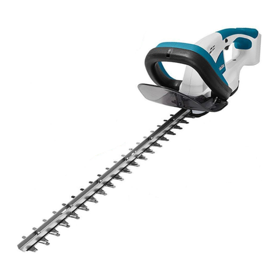
The subject models are 14.4V/18V cordless hedge trimmers.
Their main features are:
• Anti-vibration structure
• User-replaceable blade
These products are compatible with the batteries
and chargers in the list below.
Model No.
UH520D
UH422D/ 482D/ 522D BL1811G
DUH481/ 521
DUH483/ 523
S
pecification
Specification
Cell
Voltage: V
Capacity: Ah
Energy capacity: Wh
Charging time (approx.): min.
Max output (W)
Blade length: mm (")
No load speed: minˉ¹=spm
Max. cutting diameter
*6
Weight according to
EPTA-Procedure 01/2003
*5: spm= strokes per minute
*6: Indicates maximum diameter of the branch that can be received
between adjacent two blade teeth. (See the figure on right.)
*7: with battery, shear blade assembly
S
tandard equipment
Blade cover,
Battery
*8
Note: The standard equipment may vary by country or model variation.
O
ptional accessories
Shear blade complete set
Blade cover
Chip receiver assembly set
Battery BL1411G (for UH520D)
Battery BL1811G (for UH422D/ 482D/ 522D)
Battery BL1415 (for DUH481/ 521)
Battery BL1415N (for DUH481/ 521)
Battery BL1415NA (for DUH481/ 521)
Battery BL1430 (for DUH481/ 521)
Battery BL1440 (for DUH481/ 521)
UH520D
UH422D/ UH482D/ UH522D
DUH481/ DUH521
DUH483/ DUH523
Cordless Hedge Trimmer
Cordless Hedge Trimmers
Cordless Hedge Trimmers
Cordless Hedge Trimmers
Compatible
Compatible
battery
charger
BL1411G
DC18WA
DC18RC,
BL1415, BL1415N(A),
DC18SD,
BL1430(A), BL1440
DC24SC,
DC18SE,
BL1815, BL1815N,
DC18RD,
BL1820, BL1830,
DC18SF
BL1840, BL1850
Model
--- / --- / UH520D
14.4
1.1
16
60 with DC18WA
190
*5
: mm (")
--- / --- / 3.0
: kg (lbs)
(--- / --- / 6.7)
*7
, Battery cover
, Charger
*9
*8
Battery BL1815 (for DUH483/ 523)
Battery BL1815N (for DUH483/ 523)
Battery BL1820 (for DUH483/ 523)
Battery BL1830 (for DUH483/ 523)
Battery BL1840 (for DUH483/ 523)
Battery BL1850 (for DUH483/ 523)
Charger DC18WA
(for UH422D/ 482D/ 520D/ 522D)
Fast charger DC18RC
(for DUH481/ 483/ 521/ 523)
PI / NP / TE
520mm (20-1/2")
420mm/ 480mm/ 520mm
(16-1/2"/ 18-7/8"/ 20-1/2")
480mm/ 520mm (18-7/8"/ 20-1/2")
480mm/ 520mm (18-7/8"/ 20-1/2")
UH520D
UH422D/ 482D/
522D
Length (L)
DUH481/ 521
DUH483/ 523
Width (W)
Height (H)
*
with BL1430/BL1440
1
*
with BL1415/BL1415N
2
*
with BL1830/BL1840/BL1850
3
*
with BL1815/BL1815N/BL1820
4
UH422D/ 482D/ 522D
Li-ion
18
1.1
20
60 with DC18WA
210
420 (16-1/2)/ 480 (18-7/8)/ 520 (20-1/2)
2,700
ø15 (9/16)
3.0/ 3.0/ 3.1
(6.6/ 6.7/ 6.8)
*8 Battery and Charger are not supplied with
"Z" model.
*9 Supplied with the same quantity of extra Battery
OFFICIAL USE
海外営業管理承認
for ASC & Sales Shop
PRODUCT
L
W
Dimensions: mm (")
923 (36-1/4)
829 (32-5/8)/ 879 (34-1/2)/ 929 (36-1/2)
881 (34-3/4)/ 931 (36-3/4)
869 (34-1/4)/ 919 (36-1/4)
888 (35)/ 938 (37)
873 (34-3/8)/ 923 (36-1/4)
195 (7-5/8)
193 (7-5/8)
--- / DUH481/ 521
--- / DUH483/ 523
14.4
1.3, 1.5, 3.0, 4.0
1.3, 1.5, 2.0, 3.0, 4.0, 5.0
19, 22, 44, 58
24, 27, 36, 54, 72, 90
15, 15, 22, 36
15, 15, 24, 22, 36, 45
with DC18RC
190
--- / 3.0/ 3.0 (--- / 6.5/ 6.7)
,
--- / 3.0/ 3.1 (--- / 6.7/ 6.8)
*2
--- / 3.1/ 3.2 (--- / 6.9/ 7.1)
--- / 3.2/ 3.3 (--- / 7.1/ 7.3)
*1
Charger DC18SD
(for DUH481/ 483/ 521/ 523)
Charger DC24SC
(for DUH481/ 483/ 521/ 523)
Automotive charger DC18SE
(for DUH481/ 483/ 521/ 523)
Four port multi charger DC18SF
(for DUH481/ 483/ 521/ 523)
Two port multi fast charger DC18RD
(for DUH481/ 483/ 521/ 523)
P 1/ 13
H
*1
*2
*3
*4
18
with DC18RC
210
,
*4
*3
Advertisement

Related Manuals for Makita UH422D


Summary of Contents for Makita UH422D
- Page 1 Charger DC24SC Battery BL1411G (for UH520D) Battery BL1830 (for DUH483/ 523) (for DUH481/ 483/ 521/ 523) Battery BL1811G (for UH422D/ 482D/ 522D) Battery BL1840 (for DUH483/ 523) Automotive charger DC18SE Battery BL1415 (for DUH481/ 521) Battery BL1850 (for DUH483/ 523)
-
Page 2: Necessary Repairing Tools
Portion to lubricate Grease Amount The drum portion which is accepted by Bearing box a little Spindle Makita The drum portion which is accepted by Under cover grease N Spur gear 93 Teeth portion for smooth engaging with DC motor’s gear No.2... - Page 3 P 3/ 13 epair [3] DISASSEMBLY/ASSEMBLY [3] -1. Shear blade complete DISASSEMBLING Disassemble Shear blade complete as drawn in Fig. 2. Fig. 2 1. Remove Under cover by 2. Remove Shear blade complete by 3. If Nylon sleeves are left in unscrewing four M4x10 unscrewing four M5x14 Pan head screws.
- Page 4 P 4/ 13 epair [3] DISASSEMBLY/ASSEMBLY [3] -2. DC motor DISASSEMBLING (1) Disassemble Shear blade complete and Spur gear 93 as drawn in Fig. 2. (2) Remove Protector and Front grip section as drawn in Fig. 4. Fig. 4 1. Remove Protector by unscrewing 2.
- Page 5 P 5/ 13 epair [3] DISASSEMBLY/ASSEMBLY [3] -2. DC motor (cont.) DISASSEMBLING (4) Disassemble DC Motor from Motor housing as drawn in Fig. 6. Fig. 6 1. Remove one Rubber ring 6, two Rubber 2. Remove DC motor together 3. Separate DC Motor from rings 8 and five 3x16 Tapping screws.
- Page 6 P 6/ 13 epair [3] DISASSEMBLY/ASSEMBLY [3] -2. DC motor (cont.) ASSEMBLING (2) Fix Motor housing R and Motor housing L with Rubber rings as drawn in Fig. 8. Fig. 8 Rubber ring 6 Motor housing L Motor housing R Rubber ring 8 (4 pcs.) (3) Setting Motor housing section to Housing L, set Housing R in place with six 3x16 Tapping screws and one M4x65 Pan head screw as drawn in Fig.
- Page 7 P 7/ 13 epair [3] DISASSEMBLY/ASSEMBLY [3] -3. Spur Gear 93 DISASSEMBLING (1) Disassemble Shear blade complete, and then, remove Spur gear section as drawn in Fig. 2. (2) Disassemble Spur gear 93 as drawn in Fig. 11. Fig. 11 1.
- Page 8 P 8/ 13 epair [3] DISASSEMBLY/ASSEMBLY [3] -4. Front grip DISASSEMBLING (1) Remove Front grip section without disassembling Under cover as drawn in Fig. 13. Fig. 13 1. Insert a slotted screwdriver into the gap between Front Front grip Switch lever handle and Switch lever B, and push Switch lever B toward the direction designated with black arrow.
- Page 9 P 9/ 13 epair [3] DISASSEMBLY/ASSEMBLY [3] -5. Switch arm DISASSEMBLING (1) Disassemble Front grip section as drawn in Fig. 4. (2) Remove Housing R as drawn in Fig. 5. (3) Switch arm is removed as drawn in Fig. 15. Fig.
-
Page 10: Circuit Diagram
P 10/ 13 ircuit diagram Fig. D-1 Model No. DUH481/ 521 DUH483/ 523 Color index of lead wires' sheath Black Orange Purple White Yellow LED (Warning lamp for battery) Tape for bundling Lead wires Line filter Line filter is not used for some countries. - Page 11 P 11/ 13 ircuit diagram (cont.) Fig. D-2 Model No. Power source Battery UH520D BL1411G 14.4V UH422D/ 482D/ 522D BL1811G 18V Color index of lead wires' sheath Black Orange White Purple Yellow LED (Warning lamp for battery) Tape for bundling...
-
Page 12: Wiring Diagram
P 12/ 13 iring diagram Fig. D-3 Wiring to DC motor Face Lead wires (red, black) to Motor housing L side and connect their connectors with Terminals Connectors of DC motor. Controller side Red dot mark Connect Lead wire (red) to the connecting terminal near Lead wire (black) Red dot mark. - Page 13 P 13/ 13 iring diagram (cont.) Fig. D-5 Wiring in Housing set Wiring of LED warning lamp for battery Face the projected portion of LED Lamp to Front grip side. LED Lamp Groove Rib A Put LED Lamp’s Lead wires into groove. Rib B Put Lead wires between Put the following Lead wires...