
Related Manuals for Panasonic SC-HT930P-S


Summary of Contents for Panasonic SC-HT930P-S
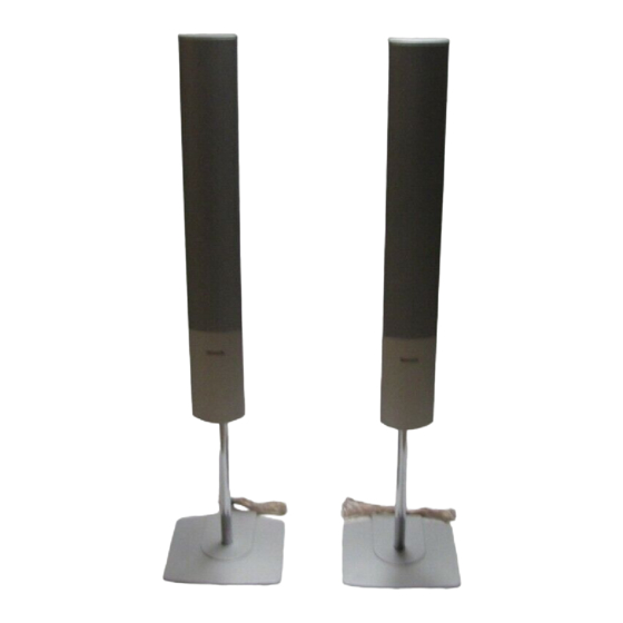
- Page 1 ORDER NO. MD0412607C0 Speaker System SB-FS930P Colour (S)... Silver Type SPECIFICATIONS Specification PDF created with pdfFactory Pro trial version www.pdffactory.com...
-
Page 2: System Combination
SB-HT930P-S consists of : SB-FS930P-S (x 2), SB-FS931P-S (x and SB-PC930P-S (x 1) 2004 Matsushita Electric Industrial Co. Ltd.. All rights reserved. Unauthorized copying and distribution is a violation of law. 1. System Combination System SC-HT930P-S SC-HT930PC-S Music Center SA-HT930P-S SA-HT930PC-S Front Speakers... - Page 3 System SC-HT930PX-S Music Center SA-HT930PX-S Front Speakers SB-FS930P-S Surround Speakers SB-FS931P-S Centre Speaker SB-PC930P-S Active Subwoofer SB-WA930PX-S System SC-HT930EE-S SC-HT930GCTS SC-HT930GN-S SC-HT935EE-S Music Center SA-HT930EE-S SA-HT930GCTS SA-HT930GN-S SA-HT935EE-S Front Speakers SB-FS930P-S Surround SB-FS880EB-S Speakers Centre Speaker SB-PC930P-S Active SB-WA930EE-S SB-WA930GCTS SB-WA930GN- SB-WA935EE- Subwoofer System...
-
Page 4: Disassembly Process
System SC-HT880E-S SC-HT880EG-S SC- HT880WEGS Music Center SA-HT880E-S SA-HT880EG-S SA- HT880WEGS Front Speakers SB-FS930P-S Surround SB-FS880EB-S Speakers Centre Speaker SB-PC930P-S Active Subwoofer SB-WA880EG-S 2. Disassembly Process 2.1. Disassembly of the Front Panel Step 1: Remove 12 screws from the Rear Cabinet Assembly. PDF created with pdfFactory Pro trial version www.pdffactory.com... - Page 5 Step 2: Push the Front Panel forward to detach from the Rear Cabinet Assembly as arrow shown above. 2.2. Disassembly of the Woofer 1 - Repeat step 1 to step 2 in item 2.1. Step 1: Detach the wires (+) red and (-) blue from the Woofer 1. PDF created with pdfFactory Pro trial version www.pdffactory.com...
- Page 6 Step 2: Remove 4 screws from the Woofer 1. 2.3. Disassembly of the Woofer 2 - Repeat step 1 to step 2 in item 2.1. Step 1: Detach the wires (+) blue and (-) gray from the Woofer 2. PDF created with pdfFactory Pro trial version www.pdffactory.com...
- Page 7 Step 2: Remove 4 screws from the Woofer 2. 2.4. Disassembly of the Tweeter - Repeat step 1 to step 2 in item 2.1. Step 1: Detach the wires (+) yellow and (-) black from the Tweeter. PDF created with pdfFactory Pro trial version www.pdffactory.com...
- Page 8 Step 2: Remove 4 screws from the Tweeter. 2.5. Disassembly of the Terminal - Repeat step 1 to step 2 in item 2.1. Step 1: Detach the wires (+) red and (-) gray from the Terminal. PDF created with pdfFactory Pro trial version www.pdffactory.com...
- Page 9 Step 2: Remove 1 screw from the Terminal. Step 3: Remove the Terminal from the Rear Cabinet Assembly. 2.6. Disassembly of the Pipe PDF created with pdfFactory Pro trial version www.pdffactory.com...
- Page 10 Step 1: Disconnect the wires (+) copper and (-) silver from the Terminal as arrow shown. Step 2: Pull out the Speaker Cable from the groove. Step 3: Remove 2 screws from the Rear Cabinet Assembly. Step 4: Pull out the Speaker Cable from Base Cover Groove. Step 5: Remove 2 screws from the Pipe.
-
Page 11: Connection Of The Speaker Cables
Step 7: Detach the Speaker Cable from Base Assembly. 3. Connection of the Speaker Cables - Be sure to connect speaker cables before connecting the AC power supply cord. - The load impedance of any speaker used with this unit must be 6 - Be sure to connect the cable from the right speaker to the right terminal and the cable from the left speaker to the left terminal. - Page 12 4. Connection of Wiring Diagram 5. Cabinet Parts Location PDF created with pdfFactory Pro trial version www.pdffactory.com...
- Page 13 PDF created with pdfFactory Pro trial version www.pdffactory.com...
-
Page 14: Replacement Parts List
6. Replacement Parts List Notes : - Important safety notice : When replacing any of these components, be sure to use only manufacturer’s specified parts shown in the parts list. - [M] indicates in the Remarks columns indicates parts supplied by PAVCSG. - Page 15 PDF created with pdfFactory Pro trial version www.pdffactory.com...
- Page 16 FLE0412W/S PDF created with pdfFactory Pro trial version www.pdffactory.com...