
Related Manuals for Panasonic AJ-D455

Summary of Contents for Panasonic AJ-D455
-
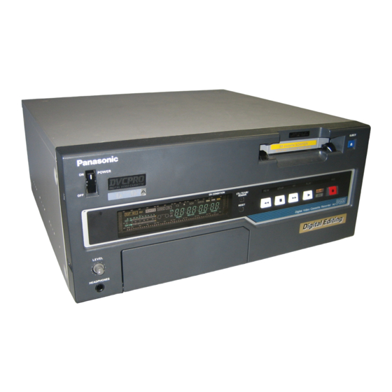
Page 1: Operating Instructions
Digital Video Cassette Recorder Operating Instructions Printed in Japan VQT9172 S0401H... - Page 2 IMPORTANT “Unauthorized recording of copyrighted televi- sion programs, video tapes and other materials may infringe the right of copyright owners and be contrary to copyright laws.” CAUTION RISK OF ELECTRIC SHOCK DO NOT OPEN CAUTION: TO REDUCE THE RISK OF ELECTRIC SHOCK, DO NOT REMOVE COVER (OR BACK).
-
Page 3: Table Of Contents
Contents General and Features ... 4 Controls and their functions Controls and their functions ... 6 • Front panel ...6 • Connector area ... 11 Tapes ...14 Setup menus Setup (default settings) ... 15 Setup menus ... 16 • SYSTEM menu ...20 •... -
Page 4: General And Features
General and Features This unit is a digital video cassette recorder which uses 1/4-inch tapes. It incorporates digital compression technology so that the deterioration in picture quality and sound quality resulting from dubbing is significantly minimized compared with existing analog systems. - Page 5 Features (continued) Multi-function input/output interfaces • Analog input/output Component (Y, P are provided. • Digital audio input/output AES/EBU audio BNC input and output connectors are provided. • Serial digital input/output Serial digital (SMPTE 259M-C, 272M-C) input/output is possible when the optional compo- nent serial interface board (AJ-YA455P) is used.
-
Page 6: Controls And Their Functions
Controls and their functions Front panel Counter Display Section POWER LEVEL HEADPHONES @2 @3 CH CONDITION CTL/TC/UB/ REMAIN RESET ! 4 !5 @ 8 @ 9 #0 # 1 # 2 SUPER MENU CH 1 PRESET DIAG AUDIO FILE REC LEVEL AUDIO PAGE MONITOR... - Page 7 q POWER switch When the ON side is pressed, the power is switched on, and the counter display lights up. w Cassette insertion slot e EJECT button When this is pressed, the tape is unloaded and several seconds later the cassette is automatically ejected.
- Page 8 Controls and their functions !4 CTL/TC/UB/REMAIN button Each time this is pressed, the counter display is switched by one setting in the following sequence: CTL “r ” appears when the remaining tape is displayed. The amount of tape remaining is displayed after “r” and the total tape length is displayed after “–”. The display shows “r –...
- Page 9 @3 Volume control This is used to adjust the headphones volume. @4 Audio recording level controls* These are used to adjust the recording levels of the audio signal CH1/CH2. @5 SUPER ON/OFF switch ON: The time code or other display is superimposed onto the signals supplied to the VIDEO OUT 3 connector.
- Page 10 Controls and their functions #2 DIAG button When this is pressed, VTR information is displayed. When it is pressed again, the original display is restored. There are two types of VTR information: “HOURS METER” information and “WARNING” information. Switching between these types is enabled by pressing the cursor buttons Indicated on the “HOUR METER”...
-
Page 11: Connector Area
Connector area ~AC IN SIGNAL r t y u i TIME CODE ANALOG VIDEO AES/EBU REF VIDEO ENCODER REMOTE RS-232C VIDEO S1-VIDEO S1-VIDEO (SUPER) !2 !3 !4 !5 REMOTE ANALOG OPTION 1 REMOTE DIGITAL AUDIO AUDIO SERIAL IN SERIAL OUT OPTION 2 DIGITAL DVCPRO/DV... - Page 12 Controls and their functions <Connector area> q AC IN socket w SIGNAL GND terminal This is connected to the signal ground terminal on the component connected to the unit in order to reduce the noise. It is not a safety ground. e Fan motor This motor drives the fan to cool down the unit.
- Page 13 !6 MONITOR OUT connector The PCM audio CH1 and/or CH2 signals (or playback signals from the CUE track) are output to this connector. PCM audio signals are output in the PLAY mode and in the –0.43 (–0.5 ) to +1 speed range; at all other times, the CUE signals are automatically output.
-
Page 14: Tapes
Also bear in mind that recordings cannot be made on a tape when the AJ-CS750 cassette adapter is used. Use of Panasonic consumer DV cassette tapes is recommended. Remember to refrain from inserting a mini DV cassette without using the cassette adapter since malfunctioning or problems may result. -
Page 15: Setup (Default Settings)
Setup (default settings) The unit’s major settings are performed by making selections on menus. The setting menus appear on the TV monitor when the TV monitor and VIDEO OUT 3 connector in the unit's connector area are hooked up. The menus can be output to the SDI OUT 3 connector as well when the AJ-YA455P component serial interface board is used. -
Page 16: Setup Menus
Setup menus This unit can store up to 5 user files (user 1 to user 5) containing different menu settings, and these files can be selected and used. Changing the file Press the MENU button. Hold down the FILE button and press the cursor button file. - Page 17 Lock mode can be set to protect the settings in the system files and user files (USER2 – USER5). Settings can no longer be changed when this mode is set. To set and release the lock mode for the system files and user files use setup item No. 30 (MENU LOCK) and setup menu item No.
- Page 18 Setup menus The contents of the USER2 – USER5 files can be copied (loaded) into the USER1 file. In addition, the contents of the USER1 file can be copied (saved) to the USER2 – USER5 files. USER1 Loading a user file Press the MENU button.
- Page 19 Saving a user file Press the MENU button. While holding down the FILE button, press the Press the button and move the cursor ( ) on the menu screen to setup item No. A01 (SAVE). SETUP-MENU <USER1> 723 DV PB ATT A00 LOAD A01 SAVE A02 P.ON LOAD...
-
Page 20: System Menu
Setup menus SYSTEM menu <SYSTEM> Item Superimposed display SYS SC COAR. SYS SC FINE SYS H ENCODER COARSE FINE AV PHASE VIDEO LEVEL SET UP LEVEL The underline on the setting item denotes the initial setting. Setting Superimposed display 0000 System phase rough adjustment: 90 units <Note>... - Page 21 SYSTEM menu <SYSTEM> Item Superimposed display CHROMA LEVEL SYS H OFFSET SYS SC/H MENU LOCK The underline on the setting item denotes the initial setting. Video output signal adjustments The SYSTEM menu item No. 03 (ENCODER SEL) and No. 22 (SYS SC/H) settings are used to make the video output signal adjustments.
-
Page 22: User Menu
Setup menus USER menu <BASIC> Item Superimposed display P-ROLL TIME CHARA H-POS CHARA V-POS DISPLAY LOCAL * The SERIAL OUT 3 con- nector functions only when the AJ-YA455P serial interface board (optional accessory) is used. The underline on the setting item denotes the initial setting. Setting Superimposed display... - Page 23 USER menu <BASIC> (continued) Item Superimposed display TAPE TIMER CHARA TYPE REMAIN * The SERIAL OUT 3 con- nector functions only when the AJ-YA455P serial interface board (optional accessory) is used. The underline on the setting item denotes the initial setting. Setting Superimposed display...
- Page 24 Setup menus USER menu <OPERATION> Item Superimposed display SHTL MAX FF. REW AUDIO MUTE ALARM PLAY DELAY CAP.LOCK EJECT EE F/R EE SEL STOP EE AUTO REW The underline on the setting item denotes the initial setting. Setting Superimposed display 0000 This sets the maximum speed for shuttle operations.
-
Page 25: Operation Menu
USER menu <OPERATION> Item Superimposed display MEMORY STOP INHIBIT REC INH LAMP EJECT SW The underline on the setting item denotes the initial setting. (continued) Setting Superimposed display 0000 This selects whether the VTR is to stop automatically when the counter value reaches “0” during a fast forwarding or 0001 rewinding operation in the CTL mode. -
Page 26: Interface Menu
1: DVCPRO’s, own ID is returned (F0 33H). 2: The unit’s own ID (A0 3CH) is returned. <Note> Set “ORIG” only when the unit is connected with a Panasonic controller (such as the AJ-A900, optional accessory). These settings are for selecting whether the RS-232C con-... - Page 27 USER menu <EDIT> Item Superimposed display STD/ NON-STD SERVO EDIT RPLCE1 EDIT RPLCE2 EDIT RPLCEC AUD EDIT AUD EDIT The underline on the setting item denotes the initial setting. Setting Superimposed display 0000 AUTO This selects STD or NON-STD in accordance with the com- posite input signal.
-
Page 28: Edit Menu
Setup menus USER menu <EDIT> (continued) Item Superimposed display AFTER CUE-UP AUD MEM UNIT VAR STEP VAR FWD VAR REV JOG STEP The underline on the setting item denotes the initial setting. Setting Superimposed display 0000 STOP This selects the mode after cue-up operation is complete. 0: STOP mode 0001 STILL1... - Page 29 USER menu <EDIT> (continued) Item Superimposed display JOG FWD JOG REV The underline on the setting item denotes the initial setting. Setting Superimposed display 0000 +4.1 This sets the maximum JOG FWD speed. 0: +4.1 (+3.1 ) speed 0001 +1.85 1: +1.85 (+1.85 ) speed 0002 2: +1 (+1 ) speed...
-
Page 30: Tape Protect Menu
Setup menus USER menu <TAPE PROTECT> Item Superimposed display STILL TIMER PROTECT DRUM STDBY STOP PROTECT DV STILL The underline on the setting item denotes the initial setting. <Note> In order to protect the tape and VTR helical heads, it is recommended that the Still Timer be set for automatic tape protection mode in 20 seconds or under. -
Page 31: Time Code Menu
USER menu <TIME CODE> Item Superimposed display VITC POS-1 VITC POS-2 VITC BLANK REGEN REGEN MODE EXT TC BINARY PHASE CORR TCG CF FLAG The underline on the setting item denotes the initial setting. Setting Superimposed display 0000 This sets the position where the VITC signal is to be inserted. (The same line as for VITC POS-2 in 501 cannot be 0006 selected.) - Page 32 Setup menus USER menu <TIME CODE> Item Superimposed display DF MODE RUN MODE TC OUT VITC OUT The underline on the setting item denotes the initial setting. SBC (Sub Code Data) area This area exists independently from the video and audio data areas on the helical track, and it contains the time code which complies with the SMPTE/EBU standard.
-
Page 33: Video Menu
USER menu <VIDEO> Item Superimposed display IN LV INT SG INPUT C KILL VSYNC V-MUTE CC (F1) BLANK CC (F2) BLANK FREEZE The underline on the setting item denotes the initial setting. Setting Superimposed display 0000 This selects the component input signal level. 0: M level. - Page 34 Setup menus USER menu <VIDEO> (continued) Item Superimposed display WIDE SELECT VIN SETUP Pb/Pr OUT The underline on the setting item denotes the initial setting. Setting Superimposed display 0000 AUTO This selects the operation to be conducted in response to the WIDE information.
- Page 35 USER menu <AUDIO> Item Superimposed display CH1 IN CH2 IN CH1 OUT CH2 OUT REC CH1 REC CH2 REC CUE OUTPUT PB FADE The underline on the setting item denotes the initial setting. Setting Superimposed display 0000 This selects the audio input (CH1) reference level switching. 0001 0002 –20dB...
-
Page 36: Audio Menu
Setup menus USER menu <AUDIO> (continued) Item Superimposed display EMBEDDED LINE CH INT SG DV PB ATT REC PT MUTE REF LEVEL The underline on the setting item denotes the initial setting. Setting Superimposed display 0000 This selects whether to superimpose the audio data onto the serial output. -
Page 37: Menu Menu
USER menu <MENU> Item Superimposed display LOAD SAVE P.ON LOAD MENU LOCK The underline on the setting item denotes the initial setting. <Notes> • No. A00 (LOAD), No. A01 (SAVE) and No. A02 (P.ON LOAD) are the menu items which can be set only for USER1. -
Page 38: Time Code
Time code/user bit Time code The time code is used when the time code signal generated by the time code generator (time code signal generator) is to be recorded on the tape, its values are to be read by the time code reader (time code signal reader), and the absolute position of the tape is to be displayed in increments of hours, minutes, seconds and frames. -
Page 39: Recording Internal/External Time Codes
Recording internal/external time codes 1. Setting the internal time code Place the VTR in the stop mode. Press the CTL/TC/UB/REMAIN button until TC is selected. Set the TC INT/EXT switch to INT. (Internal time code selected) Set the RUN MODE. (setup menu No. 510) REC (RUN): The time code runs at the same time as the recording proceeds. -
Page 40: Reproducing The Time Code/User Bit
Reproducing the time code/user bit Place the unit in the stop mode. Press the CTL/TC/UB/REMAIN button until TC or UB is selected. TC: The time code is displayed. UB: The user bit is displayed. • When it is no longer possible to read the time code, it is interpolated using the CTL signal. -
Page 41: Superimpose Screen
Superimpose screen The superimposed displays appear as shown below. The control signal, time code, etc. are indicated by abbreviations. Abbreviation TV monitor Characters displayed The background of characters superimposed on the display can be changed using setup menu No. 007 (CHARA TYPE). TV monitor Display position The position of the characters superimposed on the display can be changed using setup... -
Page 42: Servo Reference
Servo reference As the servo reference signal, this unit automatically selects the input video signal selected by the VIDEO INPUT switch, the reference video signal which is supplied from the REF VIDEO input connector or the internal sync signal. When the signal is selected, the unit’s mode and servo reference stand in the relationship shown in the flowchart presented below. -
Page 43: Rack Mounting
(AJ-MA75P) are used. For the installation rails, it is recommended that the rail and bracket for 18" length (model number CC3061-99-0400) of Chassis Trak be used. (The complete slide rail and bracket unit is not available from Panasonic.) For further details, consult with your dealer. -
Page 44: Video Head Cleaning
Video head cleaning This unit is equipped with an auto head cleaning function which automatically reduces the amount of dirt on the video heads. However, in order to maximize the unit’s reliability, it is recommended that the video heads be cleaned as and when appropriate. For further details on how to actually clean the heads, consult with one of our service companies or with your dealer. -
Page 45: Error Messages
Error messages When a warning occurs in this unit, an error number appears at the counter display. Opening the DIAG menu will display the error description on the monitor. Also, when an abnormal operation is detected in this unit, an error number flashes on the counter display. DIAG menu This display the VTR information. - Page 46 Error messages Displaying the “HOURS METER” information Press the cursor buttons ( ) to move the cursor ( ). The number for the item where the cursor is located is shown on the counter display. Item No. Item OPERATION Displays the time that the power has been supplied in one-hour units. DRUM RUN Displays the time that the drum has been rotating in one-hour units.
- Page 47 Warning Priority Error No. TV monitor display* E-10* FAN STOP High (Err-10) NO RF E-09* (Err-09) SERVO NOT LOCKED Error No. lights when servo disturbances continue for E-00* (Err-00) LOW RF E-01* (Err-01) HIGH ERROR RATE E-02* (Err-02) * Displays when warning information is checked by pressing the DIAG button. AUTO OFF mode The following error number flashes on the counter display section.
-
Page 48: Connector Signals
Connector signals VIDEO IN SERIAL IN (DIGITAL) Y, P (ANALOG) VIDEO IN REF VIDEO IN S1-VIDEO IN VIDEO OUT SERIAL OUT(DIGITAL) BNC Y, P (ANALOG) VIDEO OUT S1-VIDEO OUT AUDIO IN SERIAL IN (DIGITAL) AUDIO IN (DIGITAL) AUDIO IN (ANALOG) TIME CODE IN AUDIO OUT SERIAL OUT (DIGITAL) BNC... - Page 49 RS-232C REMOTE (25-pin D-SUB straight cable supported) Pin No. Abbreviation FRAME GROUND ENCODER REMOTE (15P) Pin No. SET UP C LEVEL Circuit Protective ground Frame ground Transmitted data Receives data from the PC. Received data Sends data to the PC. Request to send Shorted with pin 5.
-
Page 50: Printed Circuit Board
Printed circuit board CAUTION: These servicing instructions are for use by qualified service personnel only. To reduce the risk of electric shock do not perform any servicing other than that contained in the operating instructions unless you are qualified to do so. Printed circuit board... -
Page 51: Specifications
Specifications GENERAL Power supply: AC 120 V, 50 – 60 Hz Power consumption: 95 W Operating ambient temperature: 41 F to 104 F (5 C to 40 C) Operating ambient humidity: 10% to 90% (no condensation) Weight: 31.46 lbs (14.3 kg) Dimensions (W 16-3/4 6-15/16 16-3/8 inches... - Page 52 DIVISION OF MATSUSHITA ELECTRIC CORPORATION OF AMERICA Executive Office: 3330 Cahuenga Blvd W., Los Angeles, CA 90068 (323) 436-3500 EASTERN ZONE: One Panasonic Way 4E-7, Secaucus, NJ 07094 (201) 348-7621 Southeast Region: 1225 Northbrook Parkway, Ste 1-160, Suwanee, GA 30024 (770) 338-6835 Central Region:...