
Related Manuals for Panasonic HG-F Series


Summary of Contents for Panasonic HG-F Series
- Page 1 Ramco Innovations www.ramcoi.com Phone 800-280-6933 Long Range Laser Distance Sensor HG-F1 Series User’s Manual WUME-HGF1UM-2 2023.2 Ramco Innovations www.ramcoi.com Got Questions? Phone 800-280-6933 Email nsales@ramcoi.com...
- Page 2 (MEMO) WUME-HGF1UM-2 Ramco Innovations www.ramcoi.com Got Questions? Phone 800-280-6933 Email nsales@ramcoi.com...
- Page 3 Introduction Thank you for purchasing an HG-F1 series long distance laser ranging sensor. Before using this product, read and understand this User's Manual. Use the product correctly and in the optimum manner. Keep this manual in a safe location for reference whenever necessary. Manual Configuration This chapter explains safety and handling precautions, laser Chapter 1...
- Page 4 (MEMO) WUME-HGF1UM-2 Ramco Innovations www.ramcoi.com Got Questions? Phone 800-280-6933 Email nsales@ramcoi.com...
-
Page 5: Table Of Contents
Table of Contents 1 Before Using This Product..............1-1 1.1 Safety Precautions (Always observe) ..........1-2 1.2 Handling Precautions................1-3 1.3 Terminology..................1-7 1.4 Regulations and Standards ..............1-8 1.5 Laser Safety Standards ..............1-9 1.5.1 IEC / JIS / GB / KS ................1-9 1.5.2 FDA ....................1-10 1.6 Contents of Package................1-12 2 System Configuration................2-1 2.1 Principle of Measurement ..............2-2... - Page 6 5.9.2 Window Comparator Mode .............. 5-21 5.10 Analog Output Setting...............5-27 5.11 Analog Scaling Setting ..............5-28 5.12 Hysteresis Setting ................5-32 5.13 Shift Amount Setting .................5-33 5.14 External Input Setting................5-34 5.14.1 Zero Setting ................... 5-34 5.14.2 Teaching..................5-35 5.14.3 Emission Stop ................5-35 5.15 Timer Setting..................5-37 5.16 Timer Time Setting................5-40 5.17 Hold Setting ..................5-41...
-
Page 7: Before Using This Product
1 Before Using This Product 1.1 Safety Precautions (Always observe) ..........1-2 1.2 Handling Precautions................1-3 1.3 Terminology..................1-7 1.4 Regulations and Standards ..............1-8 1.5 Laser Safety Standards ..............1-9 1.5.1 IEC / JIS / GB / KS ................1-9 1.5.2 FDA ....................1-10 1.6 Contents of Package................1-12 WUME-HGF1UM-2 Ramco Innovations www.ramcoi.com Got Questions? Phone 800-280-6933 Email nsales@ramcoi.com... -
Page 8: Safety Precautions (Always Observe)
1.1 Safety Precautions (Always observe) 1.1 Safety Precautions (Always observe) This section explains important rules that must be observed to prevent personal injury and property damage. ■ Safety precautions items are classified into “WARNING” and “CAUTION” depending on the level of hazard. Risk of death or serious injury. -
Page 9: Handling Precautions
1.2 Handling Precautions 1.2 Handling Precautions ■ In this manual, the following symbols are used to indicate safety information that must be observed. Indicates an action that is prohibited or a matter that requires caution. Indicates an action that must be taken. Indicates supplemental information. - Page 10 1.2 Handling Precautions 5. The power supply unit with SELV (Safety Extra Low Voltage) or PELV (Protective Extra Low Voltage) that comply with the EMC Regulations must be used (if the UKCA marking compliance is required). 6. The power supply unit must support Class 2 (if marking compliance is required).
- Page 11 1.2 Handling Precautions ● Use shielded cables for analog output and make the line as short as possible because it is particularly liable to be affected by an external noise. ● Install the product as much as possible away from high-voltage lines, high-voltage devices, power lines, power devices, devices with large switching surges, welders, inverter motors and other noise generation sources.
- Page 12 1.2 Handling Precautions ● Although the protective structure is defined to include cables, the cable terminal is not structurally waterproof and is not subject to the protective structure. Therefore, avoid using the product in any manner that may cause water entry via the cable end. ●...
-
Page 13: Terminology
1.3 Terminology 1.3 Terminology Term Description TOF stands for time of flight. The TOF sensor measures the distance to the object to be detected by emitting light and measuring the flight time of light until the light reflected on the sensing object returns to the sensor. A display that allows the user to check the measured distance (measured value) Measurement display between the sensor and the sensing object... -
Page 14: Regulations And Standards
1.4 Regulations and Standards 1.4 Regulations and Standards ■ Conforming directives and conforming regulations EU Regulations: EMC Directive 2014/30/EU UK Regulations: EMC Regulations 2016/1091 ● Applicable standards • EN 61000-6-4 • EN 61000-6-2 USA regulations: FDA21 CFR1040.10, and 1040.11 (Laser Notice No.56 applied) ■... -
Page 15: Laser Safety Standards
1.5 Laser Safety Standards 1.5 Laser Safety Standards 1.5.1 IEC / JIS / GB / KS To prevent laser products from affecting their users, IEC, JIS, GB, and KS standards have the following respective standards: These standards classify laser products into classes according to the danger level of laser, and prescribe safety and preventive measures that should be implemented for each class. -
Page 16: Fda
1.5 Laser Safety Standards ■ Warning label The following label is affixed to the side of this product based on the safety standards for laser products. 1.5.2 FDA ■ Exporting to the US If this product is incorporated into facilities or equipment to be exported to the US, it is subject to the laser regulations of the US Food and Drug Administration (FDA). - Page 17 1.5 Laser Safety Standards ■ Certificate / identification label WUME-HGF1UM-2 1-11 Ramco Innovations www.ramcoi.com Got Questions? Phone 800-280-6933 Email nsales@ramcoi.com...
-
Page 18: Contents Of Package
1.6 Contents of Package 1.6 Contents of Package The following accessories are included in the product package. Before using the product, make sure that no items are missing. Sensor HG-F13A-A-N / NPN type, HG-F13A-A-P / PNP type ● Sensor unit ●... -
Page 19: System Configuration
2 System Configuration 2.1 Principle of Measurement ..............2-2 2.2 Description of Parts................2-3 WUME-HGF1UM-2 Ramco Innovations www.ramcoi.com Got Questions? Phone 800-280-6933 Email nsales@ramcoi.com... -
Page 20: Principle Of Measurement
2.1 Principle of Measurement 2.1 Principle of Measurement The system is designed to measure the time required for a laser beam that is emitted from the sensor and reflected on the measurement object to return to the sensor. The measured time is converted into a distance. -
Page 21: Description Of Parts
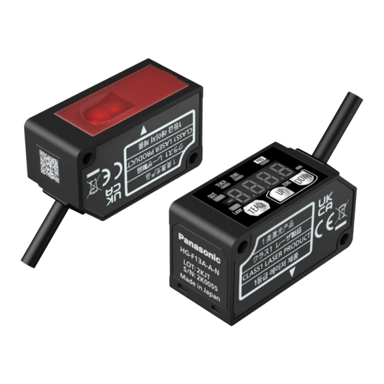
2.2 Description of Parts 2.2 Description of Parts ■ Sensor unit Name Function Beam emitting part (laser This part emits laser beams. opening) Beam receiving part This part receives the beam reflected on the measurement object. Mounting hole These hole are used to mount the sensor on machinery with M3 screws. This section is used to check measured values and indicators, as well as to Operation/display section specify and change settings for each function. - Page 22 2.2 Description of Parts Name Function Output operation indicator Lit while control output is ON. (Orange) Laser radiation indicator Lit while laser beams are being emitted. (Green) TEACH key UP key Use to change setting items and settings when configuring settings. DOWN key WUME-HGF1UM-2 Ramco Innovations www.ramcoi.com Got Questions? Phone 800-280-6933 Email nsales@ramcoi.com...
-
Page 23: Installation And Connection
3 Installation and Connection 3.1 Installation Method................3-2 3.2 Wiring Connection Diagram ..............3-4 3.3 Adjusting the beam axis..............3-5 WUME-HGF1UM-2 Ramco Innovations www.ramcoi.com Got Questions? Phone 800-280-6933 Email nsales@ramcoi.com... -
Page 24: Installation Method
3.1 Installation Method 3.1 Installation Method When mounting this product, use M3 screws (prepare separately). Tighten the screws to a torque of 0.5 N∙m or less. ● When using multiple sensors, mount them so that emitted laser beams do not directly enter the beam receiving parts of other sensors in order to avoid mutual interference. - Page 25 3.1 Installation Method WUME-HGF1UM-2 Ramco Innovations www.ramcoi.com Got Questions? Phone 800-280-6933 Email nsales@ramcoi.com...
-
Page 26: Wiring Connection Diagram
3.2 Wiring Connection Diagram 3.2 Wiring Connection Diagram HG-F13A-A-N / NPN type HG-F13A-A-P / PNP type (Note 1) Insulate unused terminals to avoid error input or short circuit. WUME-HGF1UM-2 Ramco Innovations www.ramcoi.com Got Questions? Phone 800-280-6933 Email nsales@ramcoi.com... -
Page 27: Adjusting The Beam Axis
3.3 Adjusting the beam axis 3.3 Adjusting the beam axis After installing the sensor, turn ON the power supply and confirm that the spot beam hits the workpiece. If the spot beam does not hit the workpiece, move the sensor while checking the spot beam to adjust the beam axis. - Page 28 (MEMO) WUME-HGF1UM-2 Ramco Innovations www.ramcoi.com Got Questions? Phone 800-280-6933 Email nsales@ramcoi.com...
-
Page 29: Basic Settings
4 Basic Settings 4.1 Basic Setup Procedure ...............4-2 4.1.1 Flow of Operations up to Setup Completion ........4-2 4.1.2 Emitted Beam Spot Check Mode ............. 4-4 4.1.3 2-point Teaching (Normal Sensing Mode)........4-5 4.2 Operation Check .................4-7 WUME-HGF1UM-2 Ramco Innovations www.ramcoi.com Got Questions? Phone 800-280-6933 Email nsales@ramcoi.com... -
Page 30: Basic Setup Procedure
4.1 Basic Setup Procedure 4.1 Basic Setup Procedure This section explains how to set up the product in a factory default state, using basic workpiece detection in the background as an application example. 4.1.1 Flow of Operations up to Setup Completion Described below is the flow of operations up to measurement startup. - Page 31 4.1 Basic Setup Procedure "3.3 Adjusting the beam axis" Beam axis adjustment (if the spot beam does not hit the workpiece) 1. Adjust the beam axis so that the laser spot beam hits the location to be measured on the workpiece.
-
Page 32: Emitted Beam Spot Check Mode
4.1 Basic Setup Procedure 4.1.2 Emitted Beam Spot Check Mode To make it easy to check if the laser spot beam is hitting the workpiece, you can make settings so that the spot beam becomes brighter and flashed. Use the following procedure to set the emitted beam spot check mode and perform adjustment. After turning the power ON, make sure that the following measurement display appears and then hold down the UP key for 3 seconds or longer. -
Page 33: 2-Point Teaching (Normal Sensing Mode)
4.1 Basic Setup Procedure 4.1.3 2-point Teaching (Normal Sensing Mode) After installing the sensor, set the threshold using a sensing object. Use the following procedure to perform 2-point teaching. Press the TEACH key when there is a background object. The teaching indicator is lit and “tch.2” is displayed on the digital display every 1.5 seconds. Insert a sensing object and press the TEACH key again. - Page 34 4.1 Basic Setup Procedure If the difference between the teaching results for the background object and the sensing object is equal to or larger than the shift amount, "good" will be displayed on the digital display. Then the desired threshold value is displayed and the teaching indicator turns OFF. If the difference between the teaching results is less than the shift amount or if stable sensing cannot be performed, "Hard"...
-
Page 35: Operation Check
4.2 Operation Check 4.2 Operation Check Actually detect an object with the sensor set up in "4.1 Basic Setup Procedure". ● The following procedure is for when the output operation is set to light-ON (L-on). For the setting procedure of the output operation, refer to "5.8 Output Operation Setting". - Page 36 4.2 Operation Check WUME-HGF1UM-2 Ramco Innovations www.ramcoi.com Got Questions? Phone 800-280-6933 Email nsales@ramcoi.com...
-
Page 37: Setting Items And Setting Methods
5 Setting Items and Setting Methods 5.1 List of Setting Items ................5-2 5.2 Threshold Fine Adjustment ..............5-6 5.3 Threshold Selectable ................5-7 5.4 Peak / Bottom Hold Function ..............5-9 5.5 Zero Set Function ................5-10 5.5.1 Zero Set Setting ................5-10 5.5.2 Zero Set Clearing ................5-11 5.6 Key Lock Function ................5-13 5.6.1 Key Lock Setting ................ -
Page 38: List Of Setting Items
5.1 List of Setting Items 5.1 List of Setting Items The items that can be set on the measurement display are as follows. ■ Emitted beam spot check mode Setting item Display Function Reference page screen Measurement display Emitted beam To make it easy to check if the laser spot beam is spot check mode hitting the workpiece, you can make settings so that... - Page 39 5.1 List of Setting Items ■ Peak / bottom hold function Setting item Display Function Reference page screen Measurement display Peak / bottom Used to hold the maximum value (peak value) or the hold function minimum value (bottom value) of the measured values and display it on the display.
- Page 40 5.1 List of Setting Items Setting item Display Function Reference page screen Key lock release Used to release the key lock setting. "P.5-13" <<Default: Lc.oF>> ■ PRO mode Setting item Display Function Reference page screen Measurement display Response time Used to set the time from when the sensor starts setting measurement until a measurement value is finalized "P.5-15"...
- Page 41 5.1 List of Setting Items Setting item Display Function Reference page screen Timer time Used to set the timer time when "OFF delay timer, setting ON delay timer, or One-shot timer" is set in the timer "P.5-40" setting. <<Default: 5>> Hold setting Used to set the digital display, the control output and analog output operation when a measurement error...
-
Page 42: Threshold Fine Adjustment
5.2 Threshold Fine Adjustment 5.2 Threshold Fine Adjustment ■ Overview This function allows you to adjust the threshold value (unit: mm) to any desired value on the measurement display. Press the UP key or DOWN key in the normal measurement mode, and the preset threshold value will be displayed. -
Page 43: Threshold Selectable
5.3 Threshold Selectable 5.3 Threshold Selectable ■ Overview When using the window comparator mode, set both the threshold value 1 and threshold value 2. After setting, you can switch over the threshold value or adjust each threshold value. For the procedure to set the window comparator mode, refer to "5.9.2 Window Comparator Mode". - Page 44 5.3 Threshold Selectable Setting item Set value Setting range Default value Threshold selectable Threshold value 1 (1_SL) 1,000 (When the zero set is (Note 1) 250 to 3,000 Threshold value 2 (2_SL) 2,000 cleared) Threshold value 1 (1_SL) 1,000 Threshold selectable (Note 2) -2,750 to 2,750 (When the zero set is set)
-
Page 45: Peak / Bottom Hold Function
5.4 Peak / Bottom Hold Function 5.4 Peak / Bottom Hold Function ■ Overview This function is used to hold the maximum value (peak value) or the minimum value (bottom value) of the measured values and display it on the display. The maximum value and minimum value are constantly updated during measurement. -
Page 46: Zero Set Function
5.5 Zero Set Function 5.5 Zero Set Function ■ Overview This function is used to forcibly set the measured value to "zero". You can use this function to adjust to the reference zero point when the sensor has been replaced or when the workpiece has been changed. When the zero set is set, the measured value at the location where the setting is executed is set to zero. -
Page 47: Zero Set Clearing
5.5 Zero Set Function ● Depending on where the zero set is set, the threshold value also changes. Therefore, the threshold value may exceed the sensing distance range (250 mm to 3,000 mm). If the threshold value is set outside the range, correct measurement cannot be obtained. Re-examine the measurement conditions including resetting the threshold value as necessary. - Page 48 5.5 Zero Set Function Setting item Set value Default value Zero set setting (0) Zero setting 0.oFF Zero set clearing (0.oFF) 5-12 WUME-HGF1UM-2 Ramco Innovations www.ramcoi.com Got Questions? Phone 800-280-6933 Email nsales@ramcoi.com...
-
Page 49: Key Lock Function
5.6 Key Lock Function 5.6 Key Lock Function ■ Overview This function is used to disable key operation to prevent the conditions set in each setting mode from being changed by mistake. While the key lock setting is activated, all key operations other than key lock release cannot be performed. - Page 50 5.6 Key Lock Function Setting item Set value Default value Key lock setting (Lc.on) Key lock Lc.oF Key lock release (Lc.oF) 5-14 WUME-HGF1UM-2 Ramco Innovations www.ramcoi.com Got Questions? Phone 800-280-6933 Email nsales@ramcoi.com...
-
Page 51: Response Time Setting
5.7 Response Time Setting 5.7 Response Time Setting ■ Overview This setting is used to set the time (response time) (unit: ms) from when the sensor starts measurement until a judgment value is finalized and output. ■ Setting method ● Setting the response time to a small value (fast) enables the sensor to respond to momentary changes. -
Page 52: Output Operation Setting
5.8 Output Operation Setting 5.8 Output Operation Setting ■ Overview This setting is used to set the operation mode of control output. When the operation mode is set to light-ON or dark-ON, control output operation will be as follows for each detection state. Output operation setting Detection state Light-ON... -
Page 53: Sensing Output Setting (Teaching)
5.9 Sensing Output Setting (Teaching) 5.9 Sensing Output Setting (Teaching) ■ Overview This setting is used to set the threshold teaching method. Select the output mode of the control output from the normal sensing mode or window comparator mode (1-point teaching, 2-point teaching, and 3-point teaching) The following section describes each teaching method. -
Page 54: Normal Sensing Mode
5.9 Sensing Output Setting (Teaching) 5.9.1 Normal Sensing Mode ■ Overview In this mode, control output ON/OFF is controlled for a single threshold. You can select the teaching method from either one of the following two types. Set value Operation Reference page This method is to perform teaching on the reference plane 2-point teaching... - Page 55 5.9 Sensing Output Setting (Teaching) The teaching indicator is lit and “tch.2” is displayed on the digital display every 1.5 seconds. Press the DOWN key when treating the background object as the standard. Press the UP key when treating the master workpiece as the standard. If the difference between the teaching results for the background object and the sensing object is equal to or larger than the shift amount, "good"...
- Page 56 5.9 Sensing Output Setting (Teaching) If the difference between the teaching results is less than the shift amount or if stable sensing cannot be performed, "Hard" will be displayed. Re-examine the positional relationship between the background object and the measured object and perform teaching again.
-
Page 57: Window Comparator Mode
5.9 Sensing Output Setting (Teaching) 5.9.2 Window Comparator Mode ■ Overview In this mode, control output ON/OFF is controlled by setting two thresholds (threshold 1 and threshold 2). You can select the teaching method from one of the following three types. Set value Operation Reference page... - Page 58 5.9 Sensing Output Setting (Teaching) "tch.1" will be displayed on the digital display every 1.5 seconds. Press the TEACH key. Teaching will be executed. The threshold value 1 and threshold value 2 will be set and teaching will be completed. The threshold value 1 and threshold value 2 will be set and teaching will be completed.
- Page 59 5.9 Sensing Output Setting (Teaching) If the difference between the teaching results is less than the shift amount or if stable sensing cannot be performed, "Hard" will be displayed. Re-examine the positional relationship between the background object and the measured object and perform teaching again.
- Page 60 5.9 Sensing Output Setting (Teaching) "tch.2" will be displayed on the digital display every 1.5 seconds. Insert a sensing object 2 and press the TEACH key again. Teaching for the second point will be executed. The threshold value 1 and threshold value 2 will be set and teaching will be completed. If the difference between the teaching results for the sensing object 1 and sensing object 2 is equal to or larger than the shift amount, "good"...
- Page 61 5.9 Sensing Output Setting (Teaching) With the sensing object 1 inserted, press the TEACH key. Teaching for the first point will be executed and the teaching indicator will be lit. “tch.2” will be displayed on the digital display every 1.5 seconds. Insert the sensing object 2 and press the TEACH key again.
- Page 62 5.9 Sensing Output Setting (Teaching) Insert the sensing object 3 and press the TEACH key again. Teaching for the third point will be executed. The threshold value 1 and threshold value 2 will be set and teaching will be completed. If the difference between the teaching results for the sensing objects 1 to 3 is equal to or larger than the shift amount, "good"...
-
Page 63: Analog Output Setting
5.10 Analog Output Setting 5.10 Analog Output Setting ■ Overview This setting is used to select analog output as either analog voltage output or analog current output. Output operation is performed for the selected output. Set value Output range Function Analog voltage output 0 to 5 V Outputs a voltage according to the measured value. -
Page 64: Analog Scaling Setting
5.11 Analog Scaling Setting 5.11 Analog Scaling Setting ■ Overview This setting is used to set optional two points as the upper limit value and the lower limit value for performing two-point correction on the analog output before data is output. Set the measured value A (A.SCA) as the lower limit value and the measured value B (B.SCB) as the upper limit value. - Page 65 5.11 Analog Scaling Setting ● The output value for the analog output that is outside the measurement range is a fixed value. Less than 200 mm: 0 mA More than 3,300 mm: 20.8 mA ● When the analog output is within the measurement range, the output value is limited to 20.4 mA and any value exceeding this value is not output.
- Page 66 5.11 Analog Scaling Setting ■ Setting method Measured value A (lower limit) setting 5-30 WUME-HGF1UM-2 Ramco Innovations www.ramcoi.com Got Questions? Phone 800-280-6933 Email nsales@ramcoi.com...
- Page 67 5.11 Analog Scaling Setting Measured value B (upper limit) setting ● Be sure to set the measured values to be set so that the measured value B is larger than the measured value A. Setting item Set value Setting range Default value Measured value A 0 to 2,999...
-
Page 68: Hysteresis Setting
5.12 Hysteresis Setting 5.12 Hysteresis Setting ■ Overview A hysteresis is the width of distance where the control output changes from OFF to ON or from ON to OFF. When a sensing workpiece is located near the threshold value, increasing the value of hysteresis makes output operations stable. -
Page 69: Shift Amount Setting
5.13 Shift Amount Setting 5.13 Shift Amount Setting ■ Overview This setting is used to set the shift amount when performing teaching. This setting is enabled when the window comparator mode (1-point teaching) is executed. ■ Setting method ● It cannot be set to a value that is equal to or less than twice the hysteresis. ●... -
Page 70: External Input Setting
5.14 External Input Setting 5.14 External Input Setting ■ Overview This setting is used to execute the following three functions by controlling the external input. ■ Setting method ● Hold down the DOWN key for 3 seconds or longer on the setting screen, and the setting change is suspended and the screen returns to the measurement display. -
Page 71: Teaching
5.14 External Input Setting ● The zero set that is set using the external input is cleared when the power supply is turned OFF. The zero set made at that time is not saved. ● Even when the zero set is set on the sensor side, it can be set or cleared using the external input. - Page 72 5.14 External Input Setting ● The emitted laser beam is turned ON when the external input is turned OFF from ON. The laser radiation indicator is lit when the emitted laser beam is turned ON. ● The timing chart for stopping or clearing the emission using the external input is as shown in the following diagram.
-
Page 73: Timer Setting
5.15 Timer Setting 5.15 Timer Setting ■ Overview This setting is used to set the control output timing from ON to OFF or from OFF to ON. Set value Operation OFF (No timer) No change is made in the control output timing. When the control output is turned OFF from ON, delays the OFF output for the Off delay timer’s time. - Page 74 5.15 Timer Setting ■ OFF (No timer) When the output operation setting is set to light-ON and the sensing output setting is set to normal sensing, the control output will be as shown in the following diagram. OFF delay When the timer is set to OFF delay, the output is delayed for the timer’s time set for the OFF timing.
- Page 75 5.15 Timer Setting One-shot When the timer is set to one-shot and if the setting is changed from OFF to ON again while ON is held, the ON time is extended by the timer’s time. WUME-HGF1UM-2 5-39 Ramco Innovations www.ramcoi.com Got Questions? Phone 800-280-6933 Email nsales@ramcoi.com...
-
Page 76: Timer Time Setting
5.16 Timer Time Setting 5.16 Timer Time Setting ■ Overview This setting is used to set the timer time (unit: ms) when "OFF delay timer", "ON delay timer", or "One-shot timer" is set in the timer setting. This setting is enabled when "5.15 Timer Setting"... -
Page 77: Hold Setting
5.17 Hold Setting 5.17 Hold Setting ■ Overview This setting is used to set the digital display, the control output and analog output operation when a measurement error occurs (insufficient light intensity, saturation of light intensity, out of measurement range). Operation value Hold... - Page 78 5.17 Hold Setting Setting item Set value Default value Hold last value (on) 5-42 WUME-HGF1UM-2 Ramco Innovations www.ramcoi.com Got Questions? Phone 800-280-6933 Email nsales@ramcoi.com...
-
Page 79: Eco Setting
5.18 ECO Setting 5.18 ECO Setting ■ Overview This setting is used to turn OFF the digital display to save electricity when not operating. If the ECO mode is set to ON, the digital display will turn OFF when no key is operated for 30 seconds. -
Page 80: Reset Setting
5.19 Reset Setting 5.19 Reset Setting ■ Overview This setting is used to reset all the settings of this product to the factory default settings. For the default value of each setting, refer to "5.1 List of Setting Items". ■ Setting method ●... -
Page 81: Maintenance
6 Maintenance 6.1 Maintenance and Inspection ...............6-2 6.1.1 Maintenance Precautions ..............6-2 6.1.2 Main Inspection Items ..............6-2 WUME-HGF1UM-2 Ramco Innovations www.ramcoi.com Got Questions? Phone 800-280-6933 Email nsales@ramcoi.com... -
Page 82: Maintenance And Inspection
6.1 Maintenance and Inspection 6.1 Maintenance and Inspection 6.1.1 Maintenance Precautions ● Be sure to turn off the power before cleaning the light emitting and receiving windows of the sensor. ● When cleaning the light emitting and receiving windows of the sensor, wipe them with a lint- free soft cloth or lens cleaning paper. -
Page 83: Troubleshooting
7 Troubleshooting 7.1 Solutions to Problems .................7-2 7.2 Error Display ..................7-3 WUME-HGF1UM-2 Ramco Innovations www.ramcoi.com Got Questions? Phone 800-280-6933 Email nsales@ramcoi.com... -
Page 84: Solutions To Problems
The key lock function is ON. Set the key lock function to OFF. "P.5-13" operated Important If the product still does not operate normally after you check the above, consult your Panasonic representative. WUME-HGF1UM-2 Ramco Innovations www.ramcoi.com Got Questions? Phone 800-280-6933 Email nsales@ramcoi.com... -
Page 85: Error Display
Panasonic representative. The product could be faulty. System error Please consult your Panasonic representative. Important If an error occurs again after you cleared it, consult your Panasonic representative. WUME-HGF1UM-2 Ramco Innovations www.ramcoi.com Got Questions? Phone 800-280-6933 Email nsales@ramcoi.com... - Page 86 (MEMO) WUME-HGF1UM-2 Ramco Innovations www.ramcoi.com Got Questions? Phone 800-280-6933 Email nsales@ramcoi.com...
-
Page 87: Specifications And Dimensions
8 Specifications and Dimensions 8.1 Specifications..................8-2 8.2 Shapes and Dimensions ..............8-5 8.2.1 Products ................... 8-5 8.2.2 Simple Mounting Bracket (MS-HG-01: Including two M3 screws with washer) ..................8-6 8.2.3 Simple Mounting Bracket Attachment Diagram ......8-7 8.3 I/O Circuit Diagrams................8-8 WUME-HGF1UM-2 Ramco Innovations www.ramcoi.com Got Questions? Phone 800-280-6933 Email nsales@ramcoi.com... -
Page 88: Specifications
8.1 Specifications 8.1 Specifications HG-F13A-A-N HG-F13A-A-P Model No. NPN output type PNP output type Power supply voltage 24 VDC ±10%, including 10% ripple (P-P) Current consumption 40 mA or less (at the power supply voltage of 24 VDC) (Note 2) Output type NPN open-collector transistor PNP open-collector transistor... - Page 89 8.1 Specifications HG-F13A-A-N HG-F13A-A-P Model No. NPN output type PNP output type Maximum sensing 3,000 mm distance Measurable range 250 to 3,000 mm Displayable range 200 to 3,300 mm (Note 3) Linearity ± 2% F.S. (Note 4) (at 500 mm to 3,000 mm) Red semiconductor laser: Class 1 [JIS / IEC / GB / FDA (Note 5)] Light source Maximum output: 0.39 mW, Peak emission wavelength: 680 nm...
- Page 90 8.1 Specifications HG-F13A-A-N HG-F13A-A-P Model No. NPN output type PNP output type Operating altitude (Note 2,000 m or less Emitted beam spot check mode / Threshold fine adjustment / Threshold selectable / Peak/bottom hold function / Zero set function / Key lock function / Response time setting / Output operation setting / Sensing output setting (teaching) / Analog output Various settings setting / Analog scaling setting / Hysteresis setting / Shift amount setting / External...
-
Page 91: Shapes And Dimensions
8.2 Shapes and Dimensions 8.2 Shapes and Dimensions 8.2.1 Products HG-F13A-A-N, HG-F13A-A-P Units: mm WUME-HGF1UM-2 Ramco Innovations www.ramcoi.com Got Questions? Phone 800-280-6933 Email nsales@ramcoi.com... -
Page 92: Simple Mounting Bracket (Ms-Hg-01: Including Two M3 Screws With Washer)
8.2 Shapes and Dimensions 8.2.2 Simple Mounting Bracket (MS-HG-01: Including two M3 screws with washer) Units: mm WUME-HGF1UM-2 Ramco Innovations www.ramcoi.com Got Questions? Phone 800-280-6933 Email nsales@ramcoi.com... -
Page 93: Simple Mounting Bracket Attachment Diagram
8.2 Shapes and Dimensions 8.2.3 Simple Mounting Bracket Attachment Diagram Units: mm WUME-HGF1UM-2 Ramco Innovations www.ramcoi.com Got Questions? Phone 800-280-6933 Email nsales@ramcoi.com... -
Page 94: I/O Circuit Diagrams
8.3 I/O Circuit Diagrams 8.3 I/O Circuit Diagrams HG-F13A-A-N / NPN type HG-F13A-A-P / PNP type (Note 1) Insulate unused terminals to avoid error input or short circuit. WUME-HGF1UM-2 Ramco Innovations www.ramcoi.com Got Questions? Phone 800-280-6933 Email nsales@ramcoi.com... -
Page 95: Appendix Screen Transition List
Appendix Screen Transition List Screen Transition List ................App-2 WUME-HGF1UM-2 App-1 Ramco Innovations www.ramcoi.com Got Questions? Phone 800-280-6933 Email nsales@ramcoi.com... -
Page 96: Screen Transition List
Screen Transition List Screen Transition List App-2 WUME-HGF1UM-2 Ramco Innovations www.ramcoi.com Got Questions? Phone 800-280-6933 Email nsales@ramcoi.com... - Page 97 Revision History Revision Revision date Revision item history 1st edition December 2022 Corrected caution notes to "1.4 Regulations and Standards" Deleted "Applicable regulations and certification" 2nd edition February 2023 in "8.1 Specifications" Deleted "Important Information about Order and Use of This Product" WUME-HGF1UM-2 Ramco Innovations www.ramcoi.com Got Questions? Phone 800-280-6933 Email nsales@ramcoi.com...
- Page 98 (MEMO) WUME-HGF1UM-2 Ramco Innovations www.ramcoi.com Got Questions? Phone 800-280-6933 Email nsales@ramcoi.com...
- Page 99 (MEMO) WUME-HGF1UM-2 Ramco Innovations www.ramcoi.com Got Questions? Phone 800-280-6933 Email nsales@ramcoi.com...
- Page 100 Panasonic Industry Co., Ltd. Panasonic Industrial Devices SUNX Co., Ltd. https://panasonic.net/id/pidsx/global Please visit our website for inquiries and about our sales network. Panasonic Industrial Devices SUNX Co., Ltd. 2023 February 2023 WUME-HGF1UM-2 Ramco Innovations www.ramcoi.com Got Questions? Phone 800-280-6933 Email nsales@ramcoi.com...