Toro Reelmaster 5010-H Operator's Manual
Traction unit
Hide thumbs
Also See for Reelmaster 5010-H:
- Diagnostic manual (476 pages) ,
- Service manual (335 pages) ,
- Operator's manual (128 pages)

Related Manuals for Toro Reelmaster 5010-H


Summary of Contents for Toro Reelmaster 5010-H
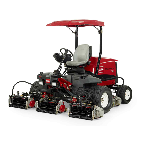
- Page 1 Form No. 3455-809 Rev A Reelmaster ® 5010-H Traction Unit Model No. 03950—Serial No. 400000000 and Up *3455-809* Register at www.Toro.com. Original Instructions (EN)
- Page 2 It is a violation of California Public Resource Code additional information, contact an Authorized Service Section 4442 or 4443 to use or operate the engine on Dealer or Toro Customer Service and have the model any forest-covered, brush-covered, or grass-covered and serial numbers of your product ready.
-
Page 3: Table Of Contents
Electrical System Safety ........63 Understanding the Warm-Up Mode....37 Disconnecting the 12 V Battery ......63 Understanding Toro Smart Power™ ....37 Connecting the 12 V Battery ......64 Starting the Engine ........... 37 Charging the 12 V Battery......... 64 Shutting Off the Engine........ -
Page 4: Safety
Safety Checking the Torque of the Wheel Nuts .............. 67 Checking the Rear-Wheel Alignment ....67 This machine has been designed in accordance Adjusting the Rear Wheel Toe-in....... 68 with EN ISO 5395 (when you complete the setup Cooling System Maintenance ......69 procedures) and ANSI B71.4-2017. -
Page 5: Safety And Instructional Decals
Safety and Instructional Decals Safety decals and instructions are easily visible to the operator and are located near any area of potential danger. Replace any decal that is damaged or missing. decal106-6754 decalbatterysymbols 106-6754 Battery Symbols 1. Warning—do not touch the hot surface. Some or all of these symbols are on your battery 2. - Page 6 decal120-4158 120-4158 1. Read the Operator’s 3. Engine—preheat Manual. 2. Engine—start 4. Engine—stop decal127-2470 127-2470 decal136-3702 136-3702 1. Warning—Read the 2. Warning—Do not modify Operator’s Manual; wear the roll bar. a seatbelt; do not remove the roll bar. decal133-8062 133-8062 decal136-3732 136-3732 1.
- Page 7 decal137-8127 137-8127 1. Attention—do not spray with high-pressure water. decal145-2549 145-2549 1. Parking brake 6. Raise the cutting units 2. Cruise control 7. PTO—Off 3. Lower the cutting units 8. PTO—On 4. Fast 9. Read the Operator’s Manual. 5. Slow decal145-2498 145-2498 1.
- Page 8 decal133-2930 133-2930 1. Warning—do not operate this machine unless you are trained. 4. Tipping hazard—drive slowly when turning; do not turn sharply while traveling fast; only drive on slopes with the cutting units lowered; always wear a seatbelt. 2. Warning—wear hearing protection. 5.
- Page 9 decal145-2572 145-2572 1. Read the Operator’s 6. Engine air filter 11. Engine coolant 16. Fluids Manual for lubrication information. 7. Engine oil 12. Engine oil level 2. Check every 8 hours. 17. Capacity 3. Brake functions 8. Fan belt 13. Fuel 18.
-
Page 10: Setup
Setup Loose Parts Use the chart below to verify that all parts have been shipped. Procedure Description Qty. – No parts required Prepare the machine. – No parts required Adjust the control-arm position. Cutting units Install the cutting units. Mount the finishing kits (finishing kits Finishing kit (sold separately) are sold separately). -
Page 11: Adjusting The Control-Arm Position
Important: Failure to properly grease the machine will result in premature failure of critical parts. Open the hood and check the coolant level; refer Installing the Cutting Units Checking the Coolant Level (page 69). Check the level of the engine-oil level, and close and latch the hood;... - Page 12 g419579 Figure 5 g027133 Figure 7 1. 48 V system connector 2. Battery disconnect jumper 1. Counterweight At each cutting unit lift arm, remove the snapper Coat the carrier-frame shaft with clean grease pin that secures the cap to the pivot yoke, and (Figure remove the cap (Figure...
- Page 13 Positioning the Turf Compensating Spring Cutting Units 2 and 4 g375690 Figure 11 g378839 Figure 9 1. Carriage bolt (3/8 x 1-1/4 3. Flange locknut (3/8 inch) inches) 1. Cutting unit 1 5. Cutting unit 5 2. Turf-compensator bracket 6. Reel motor 2.
- Page 14 g375694 Figure 13 g375274 Figure 15 1. Flange locknut (3/8 inch) 3. Capscrew 1. Cap 3. Pivot yoke 2. Right tab (Carrier frame) 2. Snapper pin 4. Carrier frame shaft Align the holes in the turf-compensator bracket Assemble the pivot yoke onto the carrier frame with the holes in the cutting-unit frame (Figure shaft.
- Page 15 g375236 Figure 17 1. Lynch pin 3. Lift arm (rear cutting unit) 2. Pivot yoke 4. Washer Assemble the pivot yoke onto the carrier frame shaft (Figure 18). g375252 Figure 16 1. Cap 3. Pivot yoke 2. Snapper pin 4. Carrier frame shaft Assemble the pivot yoke onto the carrier frame shaft.
- Page 16 g375239 g003948 Figure 19 Figure 21 1. Lynch pin 3. Lift arm 1. Lift-arm chain 3. Snapper pin 2. Lift-arm shaft 4. Washer 2. Chain bracket Insert the pivot yoke into the lift arm, and secure shaft to the arm with the lynch pin and washer. Assembling the Reel Motors to the Repeat steps through...
-
Page 17: Mounting The Finishing Kits
g316995 Figure 23 1. Center front cutting unit 4. Front left cutting unit 2. Left rear cutting unit 5. Front right cutting unit 3. Right rear cutting unit 6. Reel motor location On the front left corner of the frame (#4 cutting unit location), remove the extra flange nut on the bolt securing the bulkhead bracket to the machine... - Page 18 Repeat the procedure on the remaining 4 bulkhead locations as shown in Figure 25 through Figure Important: The connector plates are positioned differently at the remaining locations so the hose can be routed through the bulkhead bracket and to the cutting unit without getting twisted or kinked.
-
Page 19: Using The Cutting-Unit Kickstand
Using the Cutting-Unit Kickstand Parts needed for this procedure: Cutting-unit kickstand Procedure Whenever you need to tip the cutting unit to expose the bedknife/reel, prop up the rear of the cutting unit with the kickstand to make sure that the nuts on the g004144 back end of the bedbar-adjusting screws are not Figure 30... -
Page 20: Installing The Ce Hood Lock
Installing the CE Hood Lock Parts needed for this procedure: Hood lock, seal, and jam nut Washer Procedure Unlatch and raise the hood. Remove the rubber grommet from the hole in the left side of the hood (Figure 33). g419579 Figure 31 1. -
Page 21: Applying The Ce Decals
g419590 Figure 35 1. CE decal 2. Hood lock g375326 Figure 34 Remove the backing from the CE decal. 1. Hood latch 3. Seal Apply the decal to the hood. 2. Nut 4. Washer Applying the Year of Production Remove the nut from the lock. Decal Outside the hood, insert the hook end of the latch through the hole in the hood. -
Page 22: Product Overview
Product Overview g383678 Figure 37 2. Warning decal 133-2930 1. CE warning decal g260768 Figure 38 Remove the backing from the CE warning decal. 1. Engine hood 5. Seat adjustments 2. Operator's seat 6. Front cutting units Apply the CE warning decal over the existing decal. - Page 23 steering tower toward you to the most comfortable position, and release the pedal. Key Switch The key switch (Figure 39) has 3 positions: O , and S REHEAT TART Power-takeoff (PTO) Switch When the PTO switch is engaged, the machine is in g383839 Figure 40 mode, which allows you to drive up to 13 km/h...
-
Page 24: Seat Controls
Note: Ensure that you lower the cutting units after the PTO switch has been engaged to start the cutting units. When you lower the cutting units before the PTO switch is engaged, they do not start spinning. To fully raise the cutting units, pull the lever backward. When the cutting units are raised and the PTO switch is disengaged, the machine is in T mode. -
Page 25: Specifications
If you wear an implantable electronic medical To ensure optimum performance and continued safety device, consult your health care professional certification of the machine, use only genuine Toro before using this product. replacement parts and accessories. Replacement parts and accessories made by other manufacturers... -
Page 26: Performing Daily Maintenance
• • Do not add or drain fuel in an enclosed space. Fuel filter plugging may be expected for a time after converting to biodiesel blended. • Do not store the machine or fuel container where • Contact your distributor if you wish for more there is an open flame, spark, or pilot light, such information on biodiesel. -
Page 27: Using The Infocenter Lcd Display
Press the PTO switch to the D position. ISENGAGE interlock switch checks, contact your authorized Start the engine. Toro distributor. Press the traction pedal. Preparing the Machine Note: There should be no machine response when you press the traction pedal while the Drive the machine slowly to an open area. - Page 28 InfoCenter Icon Description (cont'd.) Lower the cutting units. Sit in the seat. The parking brake is on. The range is high (transport). Neutral g020650 Figure 46 The range is low (mow). 1. Indicator light 3. Middle button 2. Right button 4.
-
Page 29: Using The Menus
Controls the units used on the of the recent machine faults. InfoCenter. The menu choices Refer to the Service Manual or are English or Metric. contact your authorized Toro distributor for more information Language Controls the language used on the Faults menu and the on the InfoCenter*. -
Page 30: Protected Menus
Controls the maximum speed Mow Speed while in mow (low range) If you changed the PIN code and forgot the code, contact your authorized Toro distributor for assistance. Controls the maximum speed Trans. Speed while in transport (high range) From the M... - Page 31 Setting the Service Due Timer The service due timer resets the service due hours after a scheduled maintenance procedure is performed. In the Settings Menu, use the center button to scroll down to the P and press ROTECTED the right button. Enter PIN;...
-
Page 32: Checking The Hydrostatic Braking Distance
Setting the Maximum Allowed Refer to Setting the Reel Speed (page 39). Transport Speed Setting the Economy Mode The selected setting is displayed as an X on the Operating in economy mode can be beneficial in traction-speed bar graph along with the cruise control light-duty or noise-sensitive applications. -
Page 33: Understanding Reverse Speeds
Check if the machine stops within 0.6 m (2 ft) of the end mark (3.7 m or 12 ft). Understanding Shed Mode Contact your Toro distributor if the stopping When the horsepower requirement is greater than the distance of the machine is not within 0.6 m (2 24.8 hp of the engine, the generator will gradually... -
Page 34: Understanding The Operating Characteristics Of The Machine
Slope Safety • Operate the machine only in good visibility to avoid holes or hidden hazards. • Slopes are a major factor related to loss of control • Avoid mowing on wet grass. Reduced traction and rollover accidents, which can result in severe could cause the machine to slide. -
Page 35: Operating The Machine
maintain consistent control over rough terrain, neutral. The machine dynamically brakes to a while still allowing for quick, smooth braking. stop. • When mowing, the engine speed will automatically This traction system allows you to customize the raise to high idle. acceleration settings for operator comfort and course •... -
Page 36: Operating The Cruise Control
To disengage the cruise control use the following: • When in transport range, press the reverse traction pedal, engage the parking brake, or press the cruise control switch to the O positon. • When in mow range, press the reverse traction pedal, engage the parking brake, disengage the PTO, or press the cruise control switch to the O positon. -
Page 37: Understanding The Acceleration Mode
• On rough terrain, use the InfoCenter to control the speed. Understanding Toro Smart • Use the cruise control for turnarounds as follows: Power™ While mowing, set a safe, comfortable speed... -
Page 38: Adjusting The Turf-Compensation Spring
Adjusting the Lift-Arm Turn the key in the switch to the O position and remove the key. Counterbalance Adjusting the Rear Cutting Units Turf-Compensation Spring CAUTION The turf-compensation spring (Figure 53) transfers The springs are under tension and could the weight from the front roller to the rear roller. This cause personal injury. -
Page 39: Adjusting The Lift-Arm Turnaround Position
Adjusting the Lift-Arm Turnaround Position Park the machine on a level surface, lower the cutting units, shut off the engine, engage the parking brake, and remove the key. The lift-arm switch is located underneath the hydraulic tank and inboard of the cutting unit #5 lift arm (Figure 21). -
Page 40: Understanding The Diagnostic Light
Press the right button to change the reel speed value. As the speed setting is changed, the display continues to show the calculated reel speed based on blade count, mow speed, and HOC, but the new value is also displayed. Note: You may need to increase or decrease the reel speed to compensate for varying turf conditions. -
Page 41: Cutting Grass With The Machine
Perform a tear-shaped turn to quickly line up for your next pass. Press the lift/lower control lever to automatically lower the cutting units from the turnaround position and continue mowing. After mowing the desired area, follow the perimeter of the area to complete the cleanup mow pass. -
Page 42: After Operation
Maintaining the Machine after • Maintain proper reel to bedknife clearance. Use light contact. Mowing • Follow and maintain the 1/3rd rule (cut only 1/3 of After mowing, thoroughly wash the machine with a the grass blade at a time). garden hose with no nozzle to avoid contamination •... -
Page 43: Hauling The Machine
Pushing or Towing the Machine In an emergency, you can move the machine forward by actuating the bypass valve in the variable-displacement hydraulic pump and pushing or towing the machine. Important: Do not push or tow the machine faster than 3 to 4.8 km/h (2 to 3 mph). If you push or tow at a faster speed, internal transmission damage may occur. - Page 44 g420086 Figure 63 1. Pump mechanism on the 2. Black knob brake manifold Insert a tube or similar object, hold the black knob in on the manifold, and pump the manifold 3 times. As soon as there is substantial resistance when pumping the brake is released. Important: Do not pump the manifold after it does not pump easily.
-
Page 45: Maintenance
• To ensure safe, optimal performance of the slip-resistant footwear. Keep hands, feet, clothing, machine, use only genuine Toro replacement jewelry, and long hair away from moving parts. parts. Replacement parts made by other •... - Page 46 Maintenance Service Maintenance Procedure Interval • Grease the bearings and bushings (and immediately after every washing). • Clean the battery and check the condition of it (or weekly, whichever comes first). Every 50 hours • Check the battery-cable connections. • Inspect the cooling system hoses. Every 100 hours •...
-
Page 47: Daily Maintenance Checklist
Daily Maintenance Checklist Duplicate this page for routine use. Maintenance For the week of: Check Item Mon. Tues. Wed. Thurs. Fri. Sat. Sun. Check the safety interlock operation. Check the brake operation. Check the levels of the engine oil and fuel. Check the cooling-system fluid level. - Page 48 Important: Refer to your engine operator’s manual for additional maintenance procedures. Notation for Areas of Concern Inspection performed by: Item Date Information...
-
Page 49: Pre-Maintenance Procedures
Pre-Maintenance Closing the Hood Procedures Carefully rotate the hood closed (Figure 65). Preparing for Maintenance Park the machine on a level surface. Engage the parking brake. Disengage the PTO. Move the lower mow/raise control to the M position. Shut off the engine, and remove the key. Wait for all parts to stop moving. -
Page 50: Closing The Screen
Closing the Screen Separating the Generator Cooling-Air Shrouds Close and latch the screen (Figure 67). Remove the 4 flange-head capscrews and 4 flange locknuts that secure the upper and lower generator cooling-air shrouds (Figure 69). g378174 Figure 67 1. Ball pin 2. -
Page 51: Jacking Point Locations
g378915 Figure 70 1. Upper generator 3. Flange (generator cover) cooling-air shroud 4. Lower generator 2. Driveshaft-brush seal cooling-air shroud Align the holes in the generator cooling-air shrouds with the compression-limiting pins. Secure the halves of the generator cooling-air shrouds and compression-limiting pins with the g378913 4 flange-head capscrews and 4 flange locknuts Figure 71... -
Page 52: Lubrication
Lubrication Greasing the Bearings and Bushings Service Interval: Every 50 hours (and immediately after every washing). Grease Specification: No. 2 lithium grease Prepare the machine for maintenance; refer to Preparing for Maintenance (page 49). Open the hood; refer to Opening the Hood (page 49) Separate the generator cooling-air shrouds;... - Page 53 g012150 Figure 74 • Lift-arm pivots (1 each) (Figure • Cutting-unit carrier-frame and pivot (2 each) (Figure g003987 Figure 77 • Axle-steering pivot (1) (Figure g003960 Figure 75 • Lift-arm-pivot shaft (1 each) (Figure g004169 Figure 78 • Steering-cylinder ball joints (2) (Figure g004157 Figure 76...
-
Page 54: Engine Maintenance
Engine Maintenance Lower and latch the seat; refer to Lowering the Seat (page 50). Close and latch the hood; refer to Closing the Engine Safety Hood (page 49). • Shut off the engine before checking the oil or adding oil to the crankcase. •... -
Page 55: Servicing The Air Cleaner
g378927 g373568 Figure 81 Close and latch the hood; refer to Closing the Hood (page 49). Servicing the Air Cleaner Service Interval: Every 400 hours (more frequently in extremely dirty or dusty conditions). Service the air cleaner earlier if the air-cleaner indicator shows red. -
Page 56: Resetting The Air Filter Service Indicator
Preferred oil: SAE 15W-40 (above 0°F) • Alternate oil: SAE 10W-30 or 5W-30 (all temperatures) Toro Premium Engine Oil is available from your authorized Toro distributor in either 15W-40 or 10W-30 viscosity grades. Checking the Level of the Engine Oil... -
Page 57: Crankcase Oil Capacity
Crankcase Oil Capacity Approximately 3.3 L (3.5 US qt) with the filter. Changing the Engine Oil and Filter Service Interval: After the first 50 hours—Change the engine oil and filter. Every 150 hours Prepare the machine; refer to Preparing for Maintenance (page 49). -
Page 58: Fuel System Maintenance
Fuel System provider to correct the problem and perform all fuel system maintenance. Maintenance • Do not store diesel fuel in tanks or canisters made with zinc-plated components. Fuel Maintenance Servicing the Fuel-Water This Operator’s Manual contains more detailed fuel Separator and fuel system maintenance information than the engine Owner’s Manual, which is a general-purpose... -
Page 59: Servicing The Fuel Filter
Align a drain pan under the filter and remove the filter. Install a new filter and connect the hoses. Note: Ensure that the filter is orientated as shown in Figure g421581 Figure 88 Slide the hose clamps back into place to secure the fuel hoses to the filter. -
Page 60: Inspecting The Fuel Lines And Connections
g373900 Figure 89 1. Drain valve (fuel tank) g421595 Figure 90 Open the drain valve and allow the fuel to drain from the tank. 1. Fuel-injection pump bleed screw Use clean fuel to flush out the tank. Turn the key in the ignition switch to the O Close the drain valve. -
Page 61: Cleaning The Fuel-Pickup Tube Screen
Cleaning the Fuel-Pickup Move the clamps that secure the hoses to the fittings of the fuel sender inboard, and remove Tube Screen the hoses from the fittings (Figure 93). Removing the Fuel-Pickup Tube The fuel-pickup tube, located inside the fuel tank, comes with a screen to help prevent debris from entering the fuel system. - Page 62 Cleaning the Installing the Fuel-Pickup Tube Clean the screen at the end of the fuel pick-up tube (Figure 95). g373882 Figure 97 1. Hoses 3. Fitting (fuel sender) 2. Clamp Plug the connector of the fuel-sender harness into the connector of the machine wire harness (Figure 98).
-
Page 63: Priming The Fuel System
Electrical System Maintenance Important: Before welding on the machine, disconnect all cables from the battery, both wire harness plugs from the electronic control module, and the terminal connector from the alternator to prevent damage to the electrical system. Electrical System Safety •... -
Page 64: Connecting The 12 V Battery
Apply a coat of Grafo 112X (skin-over) grease, Toro Part No. 505-47 to the battery posts and battery-cable clamps. Slide the rubber boot over the positive battery-cable clamp. Assemble the cover over the battery, inserting the tabs of the cover into the slots in the battery tray. -
Page 65: Replacing A 12 V Fuse-Block Fuse
Replacing a 12 V Fuse-Block Fuse The fuse block is under the seat. Prepare the machine for maintenance; refer to Preparing for Maintenance (page 49). Unlatch the seat base, tilt the seat base open, and support it with the prop rods (Figure 106). -
Page 66: Replacing The Reel Enable Fuse
Close and latch the hood; refer to Closing the Hood (page 49). Replacing the Reel Enable Fuse Prepare the machine for maintenance; refer to Preparing for Maintenance (page 49). Unlatch and open the hood; refer to Opening the Hood (page 49). -
Page 67: Drive System Maintenance
Drive System Maintenance Checking the Tire Air Pressure Service Interval: Before each use or daily Important: Maintain the recommended pressure in all tires to ensure a good quality of cut and proper machine performance. Do not underinflate the tires. Prepare the machine for maintenance; refer to Preparing for Maintenance (page 49). -
Page 68: Adjusting The Rear Wheel Toe-In
Note: The rear wheel toe-in adjustment is At axle height, measure the center-to-center correct if the difference between the front wheel distance at the front and rear of the steering measurement and the rear wheel measurement tires. is 6 mm (1/4 inch) or less. (Figure 109). -
Page 69: Cooling System Maintenance
Cooling System • Preferred option: If distilled water is not available, use a pre-mix coolant instead of a concentrate. Maintenance • Minimum requirement: If distilled water and pre-mix coolant are not available, mix concentrated coolant with clean drinkable water. Cooling System Safety Checking the Coolant Level •... -
Page 70: Removing Debris From The Cooling System
Close and latch the hood; refer to Closing the Hood (page 49). Removing Debris from the Cooling System Service Interval: Before each use or daily Every 100 hours—Inspect the cooling system hoses. Every 2 years—Flush and replace the cooling g379098 system fluid. -
Page 71: Belt Maintenance
A machine using the recommended replacement fluid requires less frequent fluid and filter changes. Alternative hydraulic fluids: If Toro PX Extended Life Hydraulic Fluid is not available, you may use another conventional, petroleum-based hydraulic fluid having specifications that fall within the listed range... -
Page 72: Checking The Hydraulic-Fluid Level
Remove the cap/dipstick from the filler neck and This fluid is compatible with the elastomers used wipe it with a clean rag. in Toro hydraulic systems and is suitable for a Insert the dipstick into the filler neck; then wide-range of temperature conditions. This fluid is remove it and check the level of fluid. -
Page 73: Checking For Leaks
If the fluid becomes contaminated, contact your Toro Distributor because the system must be flushed. Contaminated fluid looks milky or black when compared to clean fluid. -
Page 74: Cutting Unit Maintenance
Cutting Unit Maintenance Fill the tank with the specified hydraulic fluid; refer to Hydraulic Fluid Specification (page 71) Hydraulic Fluid Capacity (page 73). Blade Safety Important: Use only the hydraulic fluids specified. Other fluids could cause system A worn or damaged blade or bedknife can break, and damage. - Page 75 Note: Additional instructions and procedures on Moving the Lower Mow/Raise lever backlapping are available in the Toro Reel Mower rearward and press the PTO switch to Basics (with sharpening guidelines), Form 09168SL. disengage the PTO. Note: When backlapping, the front units all operate Shut off the engine and remove the key.
-
Page 76: Chassis Maintenance
Extended Maintenance Chassis Maintenance Inspecting the Seat Belt Chassis and Engine Service Interval: Before each use or daily Service Interval: Every 2 years—Replace the hydraulic hoses. Inspect the seat belt for wear, cuts, and other damage. Replace the seat belt(s) if any Every 2 years—Replace the coolant hoses. -
Page 77: Cleaning
Clean the battery, terminals, and posts with a wire brush and baking-soda solution. Coat the cable terminals and battery posts with Grafo 112X skin-over grease (Toro Part No. 505-47) or petroleum jelly to prevent corrosion. Slowly charge the battery every 60 days for 24 hours to prevent lead sulfation of the battery. -
Page 78: Preparing The Engine
Preparing the Engine Drain the engine oil from the oil pan and install the drain plug. Remove and discard the oil filter. Install a new oil filter. Fill the engine with specified motor oil. Start the engine and run it at idle speed for approximately 2 minutes. - Page 79 Notes:...
- Page 80 Notes:...
- Page 81 The Toro Company (“Toro”) respects your privacy. When you purchase our products, we may collect certain personal information about you, either directly from you or through your local Toro company or dealer. Toro uses this information to fulfil contractual obligations - such as to register your warranty, process your warranty claim or to contact you in the event of a product recall - and for legitimate business purposes - such as to gauge customer satisfaction, improve our products or provide you with product information which may be of interest.
- Page 82 While the exposure from Toro products may be negligible or well within the “no significant risk” range, out of an abundance of caution, Toro has elected to provide the Prop 65 warnings. Moreover, if Toro does not provide these...
- Page 83 Countries Other than the United States or Canada Customers who have purchased Toro products exported from the United States or Canada should contact their Toro Distributor (Dealer) to obtain guarantee policies for your country, province, or state. If for any reason you are dissatisfied with your Distributor's service or have difficulty obtaining guarantee information, contact your Authorized Toro Service Center.