Siemens SIMATIC NET RUGGEDCOM RS900GP Installation Manual
Rugged ethernet switches
Hide thumbs
Also See for SIMATIC NET RUGGEDCOM RS900GP:
- Installation manual (46 pages) ,
- Installation manual (44 pages) ,
- Installation manual (46 pages)

Related Manuals for Siemens SIMATIC NET RUGGEDCOM RS900GP


Summary of Contents for Siemens SIMATIC NET RUGGEDCOM RS900GP
- Page 1 Edition 11/2022 Installation Manual SIMATIC NET Rugged Ethernet Switches RUGGEDCOM RS900GP https://www.siemens.com/ruggedcom...
- Page 2 Preface Introduction Installing the Device SIMATIC NET Device Management Rugged Ethernet Switches RUGGEDCOM RS900GP Communication Ports Technical Specifications Installation Manual Certification 11/2022 C79000-G8976-1026-09...
- Page 3 Note the following: WARNING Siemens products may only be used for the applications described in the catalog and in the relevant technical documentation. If products and components from other manufacturers are used, these must be recommended or approved by Siemens. Proper transport, storage, installation, assembly, commissioning, operation and maintenance are required to ensure that the products operate safely and without any problems.
-
Page 4: Table Of Contents
Accessing Documentation ....................... v Registered Trademarks ......................v Warranty ..........................vi Training ..........................vi Customer Support ........................vi Contacting Siemens ....................... vii Introduction ........................... 1 Feature Highlights ....................1 Description ......................2 Required Tools and Materials ................. 3 Decommissioning and Disposal ................3 Supported Fiber Optic Cables ................ - Page 5 Table of Contents Power Supply Specifications ................23 PoE Output Specifications ..................23 Failsafe Alarm Relay Specifications ..............23 Copper Ethernet Port Specifications ..............24 Fiber Optic Ethernet Port Specifications ............... 24 Operating Environment ..................25 Mechanical Specifications ..................25 Dimension Drawings ...................
-
Page 6: Preface
SIMATIC NET Glossary The SIMATIC NET Glossary describes special terms that may be used in this document. The glossary is available online via Siemens Industry Online Support (SIOS) at: https://support.industry.siemens.com/cs/ww/en/view/50305045 Accessing Documentation The latest user documentation for RUGGEDCOM RS900GP is available online at https://support.industry.siemens.com. -
Page 7: Warranty
Preface Warranty Warranty Siemens warrants this product for a period of five (5) years from the date of purchase, conditional upon the return to factory for maintenance during the warranty term. This product contains no user-serviceable parts. Attempted service by unauthorized personnel shall render all warranties null and void. -
Page 8: Contacting Siemens
Call a local hotline center to submit a Support Request (SR). To locate a local hotline center, visit https://w3.siemens.com/aspa_app/?lang=en. Mobile App Install the Industry Online Support app by Siemens AG on any Android, Apple iOS or Windows mobile device and be able to: •... - Page 9 Preface Contacting Siemens viii RUGGEDCOM RS900GP Installation Manual, 11/2022, C79000-G8976-1026-09...
-
Page 10: Introduction
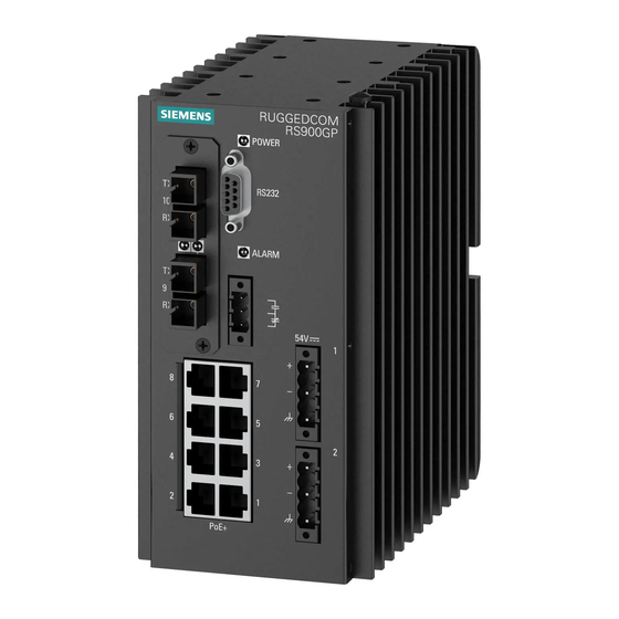
Introduction The RUGGEDCOM RS900GP is an industrially hardened, fully managed Ethernet switch providing dual fiber optical Gigabit Ethernet ports and eight Fast Ethernet copper ports, each capable of supplying high power 802.3at compliant Power over Ethernet (PoE). Designed to operate reliably in harsh industrial environments, the RUGGEDCOM RS900GP provides a high level of immunity to electromagnetic interference and heavy electrical surges typical of environments found in electric utility substations, factory floors or in curb side traffic control cabinets. -
Page 11: Description
Introduction 1.2 Description Universal Power Supply Options Power Supply • Single 54 VDC, 255 W (or greater) external power supply can deliver 30 W x 8 port per IEEE 802.3at • Second power supply input for a redundant 54 V power supply •... -
Page 12: Required Tools And Materials
Introduction 1.3 Required Tools and Materials RS-232 Console Port The serial console port is for interfacing directly with the device and accessing initial management functions. For information about connecting to the device via the serial console port, refer to "Connecting to the Device" (Page 15). -
Page 13: Supported Fiber Optic Cables
Introduction 1.5 Supported Fiber Optic Cables equipment. Recycling and disposal must be done in accordance with local regulations. Supported Fiber Optic Cables The following fiber optic cable types are supported under the stated conditions. Cable Type Wavelength (nm) Modal Bandwidth Distance (m) (MHz·km) 100Base-FX 1000Base-SX... -
Page 14: Installing The Device
Installing the Device This chapter describes how to install the device, including mounting the device, connecting power, and connecting the device to the network. DANGER Electrocution hazard – risk of serious personal injury and/or damage to equipment Before performing any maintenance tasks, make sure all power to the device has been disconnected and wait approximately two minutes for any remaining energy to dissipate. -
Page 15: General Procedure
If any item is missing or damaged, contact Siemens for assistance. Cabling Recommendations Siemens does not recommend the use of copper cabling of any length for critical, real-time substation automation applications. All copper Ethernet ports on RUGGEDCOM products include transient suppression circuitry to protect against... -
Page 16: Mounting The Device
1 standards. This means that during a transient electrical event, communications errors or interruptions may occur, but recovery is automatic. Siemens also does not recommend using copper Ethernet ports to interface with devices in the field across distances that could produce high levels of ground potential rise (i.e. - Page 17 Installing the Device 2.4.1 Mounting the Device on a DIN Rail DIN Rail Bracket Screw Figure 2.1 DIN Rail Bracket Assembly Hook the top teeth of the adapter onto the DIN rail. Note The adapter features a sliding release with a slot at the bottom for a flathead screwdriver.
-
Page 18: 2.4.2 Mounting The Device To A Panel
Installing the Device 2.4.2 Mounting the Device to a Panel DIN Rail Adapter Figure 2.2 Mounting the Device to a DIN Rail Insert a flathead screw driver into the slot of the sliding release and move it down. Push the device against the bottom of the DIN rail. Let go of the sliding release to latch the device. - Page 19 Installing the Device 2.4.2 Mounting the Device to a Panel Rear Mount Orientation Front Mount Orientation Side Mount Orientation Figure 2.4 Panel Mount Options Secure the adapters to the device in the desired orientation. Place the device against (side or rear mount orientation) or insert it into (front mount orientation) the panel and align the adapters with the mounting holes.
-
Page 20: Grounding The Device
Installing the Device 2.5 Grounding the Device Install #6 screws (not supplied) to secure the adapters to the panel. Grounding the Device The RUGGEDCOM RS900GP chassis features a threaded hole for connecting the device to ground (Earth). It is recommended to terminate the ground connection with an M3 ring or spade lug, and then torque to 1.7 N·m (15 lbf-in). -
Page 21: Connecting Power
For IEC 61850 compliance, use an IEC 61850 compliant PoE power supply with power cabling no longer than 3 m (118 in). Otherwise, Siemens recommends using the RUGGEDCOM RPS1300 switch-mode AC power supply. For more information about this power supply, refer to https:// support.industry.siemens.com/cs/ww/en/view/109478699. - Page 22 Installing the Device 2.7 Connecting Power To connect a power source to the low DC power supply, do the following: Secure a European-style terminal block (or Euroblock) to one of the available terminals. Connect the positive wire from the power source to the positive terminal on the terminal block.
- Page 23 Installing the Device 2.7 Connecting Power RUGGEDCOM RS900GP Installation Manual, 11/2022, C79000-G8976-1026-09...
-
Page 24: Device Management
Device Management This section describes how to connect to and manage the device. Connecting to the Device The following describes the various methods for accessing the RUGGEDCOM RS900GP console and Web interfaces on the device. For more detailed instructions, refer to the "RUGGEDCOM RS900GP User Guide" for the RUGGEDCOM RS900GP. Serial Console Port Connect a PC or terminal directly to the serial console port to access the boot-time control and RUGGEDCOM ROS console interface. -
Page 25: Configuring The Device
Device Management 3.2 Configuring the Device Name Description Reserved (Do Not Connect) Connected internally. Connected internally. Communication Ports Connect any of the available Ethernet ports on the device to a management switch and access the RUGGEDCOM RS900GP console and Web interfaces via the device's IP address. -
Page 26: Communication Ports
Communication Ports The RUGGEDCOM RS900GP features eight standard 10/100Base-TX copper RJ45 Ethernet ports capable of Power-over-Ethernet (PoE). It can also be equipped with two additional Gigabit Ethernet capable ports, for which many fiber transceiver and copper options are available. Each communication port type has a specific place in the RUGGEDCOM RS900GP chassis. - Page 27 Communication Ports 4.1 Copper Ethernet Ports WARNING Electric shock hazard – risk of serious personal injury and/or equipment interference If shielded cables are used, make sure the shielded cables do not form a ground loop via the shield wire and the RJ45 receptacles at either end. Ground loops can cause excessive noise and interference, but more importantly, create a potential shock hazard that can result in serious injury.
- Page 28 Communication Ports 4.1 Copper Ethernet Ports Name Description 10/100Base- 1000Base- BI_DB- Receive Data- or Bi- Directional BI_DA+ Transmit Data+ or Bi- Directional Reserved BI_DD+ (Do Not Directional Connect) Reserved BI_DD- (Do Not Directional Connect) BI_DA- Transmit Data- or Bi- Directional Reserved BI_DC+ (Do Not Directional...
-
Page 29: Poe Ports
Communication Ports 4.2 PoE Ports PoE Ports The RUGGEDCOM RS900GP supports eight 10/100Base-TX Power over Ethernet (POE) ports (ports 1 to 8). Each port complies with the IEEE 802.3at and IEEE 802.3af standards, and feature the ability to automatically enable/disable power when PoE- capable devices are connected or removed. -
Page 30: Fiber Optic Ethernet Ports
Communication Ports 4.3 Fiber Optic Ethernet Ports Pin-Out The pin-out for the PoE ports is as follows: Name Description Receive Data+ Receive Data- Transmit Data+ Figure 4.7 RJ45 Ethernet Port Pin Configuration Transmit Data- Specifications For specifications on the available PoE ports, refer to "Copper Ethernet Port Specifications"... -
Page 31: Sfp Transceivers
"RUGGEDCOM SFP Transceiver Catalog [https:// support.industry.siemens.com/cs/ca/en/view/109482309]". NOTICE Only use SFP transceivers approved by Siemens for RUGGEDCOM products. Siemens accepts no liability as a result of performance issues related in whole or in part to third-party components. RUGGEDCOM RS900GP... -
Page 32: Technical Specifications
Technical Specifications This section provides important technical specifications related to the device. Power Supply Specifications Power Minimum Maximum Fuse Rating Isolation Maximum Maximum Supply Type Input Input Power Combined Consumption Power Output at PoE Ports 54 VDC 45 VDC 57 VDC 6.3A (T) 1.5 kVDC 15 W... -
Page 33: Copper Ethernet Port Specifications
Note • Maximum segment length is greatly dependent on factors such as fiber quality, and the number of patches and splices. Consult a Siemens Sales associate when determining maximum segment distances. • All optical power numbers are listed as dBm averages. -
Page 34: Operating Environment
Technical Specifications 5.6 Operating Environment Mode Connector Cable Tx λ Tx min. Tx max. Distance Power Type Type (nm) (dBm) (dBm) Sensitivity Saturation (km) Budget (μm) (dBm) (dBm) (dB) 9/125 1300 9/125 1300 9/125 1300 Typical. Gigabit Ethernet (1 Gbps) Optical Specifications Cable Power Connector... -
Page 35: Dimension Drawings
Technical Specifications 5.8 Dimension Drawings Dimension Drawings Note All dimensions are in millimeters, unless otherwise stated. 89.9 154.4 Figure 5.1 Overall Dimensions RUGGEDCOM RS900GP Installation Manual, 11/2022, C79000-G8976-1026-09... - Page 36 Technical Specifications 5.8 Dimension Drawings 44.5 38.1 156.9 26.0 64.1 Figure 5.2 Panel Mount Dimensions (Rear Mount Shown) RUGGEDCOM RS900GP Installation Manual, 11/2022, C79000-G8976-1026-09...
- Page 37 Technical Specifications 5.8 Dimension Drawings 44.5 90.0 41.4 17.8 38.1 137.9 Figure 5.3 Panel Mount Dimensions (Side Mount Shown) RUGGEDCOM RS900GP Installation Manual, 11/2022, C79000-G8976-1026-09...
- Page 38 Technical Specifications 5.8 Dimension Drawings 174.2 163.1 175.8 Figure 5.4 DIN Rail Mount Dimensions RUGGEDCOM RS900GP Installation Manual, 11/2022, C79000-G8976-1026-09...
- Page 39 Technical Specifications 5.8 Dimension Drawings RUGGEDCOM RS900GP Installation Manual, 11/2022, C79000-G8976-1026-09...
-
Page 40: Certification
Approvals This section details the standards to which the RUGGEDCOM RS900GP complies. Note All relevant certificates and test reports are available on Siemens Industry Online Support [https://support.industry.siemens.com]. 6.1.1 UKCA This device is certified for use in Great Britain and bears the United Kingdom Certified Assessed (UKCA) marking. -
Page 41: European Union (Eu)
Certification 6.1.3 European Union (EU) 6.1.3 European Union (EU) This device is declared by Siemens Canada Ltd. to comply with essential requirements and other relevant provisions of the following EU directives: • EN 62368-1 Information Technology Equipment – Safety – Part 1: General Requirements •... -
Page 42: Fda/Cdrh
Title 21 Code of Federal Regulations (CFR) – Chapter I – Sub-chapter J – Radiological Health 6.1.6 ISED This device is declared by Siemens Canada Ltd. to meet the requirements of the following ISED (Innovation Science and Economic Development Canada) standard: • CAN ICES-3 (A)/NMB-3 (A) 6.1.7... -
Page 43: 6.1.9 Rohs
Certification 6.1.9 RoHS 6.1.9 RoHS This device is declared by Siemens Canada Ltd. to meet the requirements of the following RoHS (Restriction of Hazardous Substances) directives for the restricted use of certain hazardous substances in electrical and electronic equipment: • China RoHS 2... - Page 44 Certification 6.2 EMC and Environmental Type Tests Test Description Test Levels Severity Levels Earth 10 V Ground Ports Magnetic Field Enclosure 40 A/m Continuous 61000-4-8 Ports 1000 A/m for 1 s Voltage Dips and Interrupts DC Power 30% for 0.1 s ...
- Page 45 Certification 6.2 EMC and Environmental Type Tests Description Test Levels Oscillatory Signal Ports 2.2 kV Common Mode @ 1 MHz DC Power Ports 2.2 kV Common and Differential Mode @ 1 MHz HV Impulse Signal Ports 5 kV (Failsafe Relay) DC Power Ports 5 kV Dielectric Strength Signal Ports...
- Page 46 For more information Siemens RUGGEDCOM https://www.siemens.com/ruggedcom Industry Online Support (service and support) https://support.industry.siemens.com Industry Mall https://mall.industry.siemens.com Siemens Canada Ltd. Digital Industries Process Automation 300 Applewood Crescent Concord, Ontario, L4K 4E5 Canada © 2022 Siemens Canada Ltd. Subject to change...