Siemens SIMOTICS XP 1MB5 Operating Instructions Manual
Low-voltage motors
Hide thumbs
Also See for SIMOTICS XP 1MB5:
- Operating instructions manual (174 pages) ,
- Operating instructions manual (166 pages)

Related Manuals for Siemens SIMOTICS XP 1MB5


Summary of Contents for Siemens SIMOTICS XP 1MB5
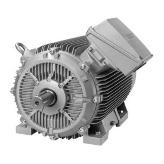
- Page 1 Edition 04/2023 OPERATING INSTRUCTIONS SIMOTICS XP Low-voltage motors 1MB5 Shaft height 400/450 www.siemens.com/drives...
- Page 3 Introduction Safety information Description SIMOTICS XP Preparing for use Niederspannungsmotoren 1MB5 shaft height 400/450 Assembly Electrical connection Operating Instructions Commissioning Operation Maintenance Spare parts Disposal Technical data Quality documents For use in Zone 2 (IEC/EN 60079-10-1) For use in Zone 21 and 22 (IEC/EN 60079-10-2) Translation of the original instructions 04/2023 A5E52802354A...
- Page 4 Note the following: WARNING Siemens products may only be used for the applications described in the catalog and in the relevant technical documentation. If products and components from other manufacturers are used, these must be recommended or approved by Siemens. Proper transport, storage, installation, assembly, commissioning, operation and maintenance are required to ensure that the products operate safely and without any problems.
-
Page 5: Table Of Contents
Websites of third-party companies..................11 SIMOTICS documentation ....................11 Service and support ......................12 1.4.1 Siemens Industry Online Support on the Web..............12 1.4.2 Siemens Industry Online Support on the road..............13 1.4.3 Feedback on the technical documentation ................. 14 1.4.4... - Page 6 Table of contents 3.3.4 Degree of protection ......................30 3.3.5 Environmental conditions ....................30 3.3.6 Optional built-on and built-in accessories ................31 3.3.7 Marking ..........................31 Preparing for use ..........................33 Safety-related aspects to consider when configuring the plant ..........33 Observing the operating mode...................
- Page 7 Table of contents Lift the machine to where it will be mounted and position it ..........55 5.3.1 Lift the machine to where it will be mounted and position it ..........55 5.3.2 Checking the attachment points..................56 5.3.3 Ensure adequate cooling ....................57 5.3.4 Balancing...........................
- Page 8 Table of contents 6.7.6 Using single-stranded cables ....................86 6.7.7 Connecting aluminum conductors..................87 6.7.8 Minimum air clearances ..................... 87 6.7.9 Connection using saddle terminals ..................88 Finishing connection work ....................88 Connecting the auxiliary circuits..................89 6.9.1 Selecting cables ......................... 89 6.9.2 Bringing cables into the auxiliary terminal box and routing them ........
- Page 9 Table of contents Safety instructions for maintenance ................. 109 Inspection and maintenance .................... 110 9.3.1 Safety instructions for inspection and maintenance ............110 9.3.2 General inspection specifications..................112 9.3.3 First inspection after installation or repair................. 112 9.3.4 Main inspection ....................... 113 9.3.5 Maintenance intervals......................
- Page 10 Table of contents 10.6 Rolling bearings ......................138 10.7 Groups of parts ........................ 138 10.8 Machine parts........................140 10.8.1 Stator and rotor ....................... 140 10.8.2 Ventilation........................141 10.8.3 External fan ........................142 10.8.4 TB3R61 terminal box......................143 10.8.5 Terminal box 1XB1631 ..................... 144 10.8.6 Main terminal box, type 1XB7750 ..................
-
Page 11: Introduction
Introduction About SIMOTICS Description SIMOTICS is the Siemens family of electric motors addressing the complete motor spectrum in Digital Industry. About this manual 1.2.1 Content To illustrate possible application areas for our products, typical use cases are listed in this product documentation and in the online help. -
Page 12: Target Group
This document contains recommendations relating to third-party products. Siemens accepts the fundamental suitability of these third-party products. You can use equivalent products from other manufacturers. Siemens does not accept any warranty for the properties of third-party products. 1.2.2 Target group... -
Page 13: Standard Scope
This document may contain hyperlinks to third-party websites. Siemens is not responsible for and shall not be liable for these websites and their content. Siemens has no control over the information which appears on these websites and is not responsible for the content and information provided there. -
Page 14: Service And Support
Service and support 1.4.1 Siemens Industry Online Support on the Web Description The following is available via Siemens Industry Online Support (https:// support.industry.siemens.com/cs/ww/en/), among others: • Product support • Global forum for information and best practice sharing between users and specialists... -
Page 15: Siemens Industry Online Support On The Road
• Compatibility tool • Newsletters with information about your products • Catalogs/brochures 1.4.2 Siemens Industry Online Support on the road Description Figure 1-1 "Siemens Industry Online Support" app The "Industry Online Support" app supports you in the following areas, for example: •... -
Page 16: Feedback On The Technical Documentation
1.4.3 Feedback on the technical documentation Description We welcome your questions, suggestions, and corrections for this technical documentation. Please use the "Provide feedback" link at the end of the entries in Siemens Industry Online Support. Figure 1-2 Requests and feedback 1.4.4... -
Page 17: Technical Support
• "Industry Online Support" mobile app The Support Request is the most important input channel for questions relating to products from Siemens Industry. This will assign your request a unique ticket number for tracking purposes. The Support Request offers you: •... -
Page 18: Training
Description SITRAIN – Digital Industry Academy offers a comprehensive range of training courses on Siemens industrial products – directly from the manufacturer, for all industries and use cases, for all knowledge levels from beginner to expert. More information can be found on the Internet via the following address (https:// www.siemens.com/sitrain). -
Page 19: Safety Information
Safety information Information for those responsible for the plant/system This motor is a partly completed machine in the sense of directive 2006/42/EC ("machinery directive"), and has been designed and built in compliance with the applicable's health and safety protection requirements of this directive, including the protection goals of directive 2014/35/EU ("Low-Voltage Directive") regarding electrical hazards. -
Page 20: Qualified Personnel
Safety information 2.4 Safe handling 5 safety rules 1. Disconnect the system. Also disconnect the auxiliary circuits, for example, anti-condensation heating. 2. Secure against reconnection. 3. Verify absence of operating voltage. 4. Ground and short-circuit. 5. Provide protection against adjacent live parts. To energize the system, apply the measures in reverse order. - Page 21 Safety information 2.4 Safe handling Danger as a result of stationary parts under voltage (live parts) Live parts represent a hazard. Touch protection against active (live) parts is no longer guaranteed if covers are removed. The minimum clearance and creepage distances may be violated when coming close to live parts.
-
Page 22: Use In Hazardous Areas
Safety information 2.5 Use in hazardous areas Use in hazardous areas Electrical installations in hazardous zones must be mounted, installed and operated by the applicable responsible persons in accordance with the applicable rules and regulations. Note The basic requirements relating to electrical installations and their operation in hazardous areas are described, for instance, in directive 1999/92/EC as well as in standard IEC / EN 60079-14 or when using the electrical machine outside the European Community, in the country-specific regulations. -
Page 23: Electrostatic Sensitive Devices
Safety information 2.6 Electrostatic sensitive devices An explosion can occur. This can result in death, serious injury or material damage. • For this reason, the relative characteristics must be considered both for gas (zones 0, 1 and 2) and for dust (zones 20, 21 and 22) where hybrid mixtures arise. It is necessary for a competent assessor to determine in the individual case whether the parameters determining ignition are unfavorably affected in a particular hybrid mixture. -
Page 24: Risk Of Explosion Due To Electrostatic Discharge
Safety information 2.7 Risk of explosion due to electrostatic discharge • Electronic modules should not be brought into contact with electrically insulating materials, such as: – Plastic film – Plastic parts – Insulating table supports – Clothing made of synthetic fibers •... -
Page 25: Processes That Generate High Levels Of Electrostatic Charge
Safety information 2.9 Electromagnetic fields when operating electrical power engineering installations • Use the tested, original paint when recoating or touching up. • Carefully check repaired or subsequently applied coating systems to ensure that they strictly comply with the electrostatic requirements according to IEC/EN 60079-0. •... -
Page 26: Special Designs And Construction Versions
Safety information 2.10 Special designs and construction versions Electrical power equipment generate electromagnetic fields during operation. Potentially lethal malfunctions can occur in medical implants, e.g. pacemakers, in the vicinity of electrical power equipment. Data may be lost on magnetic or electronic data carriers. •... -
Page 27: Description
Description Area of application The rotating electrical motors of this series are used as industrial drives. They are designed for a wide range of drive applications both for line operation as well as in conjunction with frequency converters. They are characterized by their high power density, extreme robustness, long service life and outstanding reliability. -
Page 28: Rating Plate
Description 3.2 Rating plate Type of protection Ex tc This machine has "Protection through enclosure" (Ex tc IIIB) type of protection according to IEC / EN 60079‑0 and IEC / EN 60079‑31. This machine is suitable for operation in hazardous areas with flammable, non-conductive dust in accordance with Zone 22 as per IEC / EN 60079‑10‑2. -
Page 29: Structure
Description 3.3 Structure Data on the rating plate Manufacturer specifications Voltages with connection type Type of motor (10) Frequencies Motor type (11) Currents Order number (12) Power ratings Serial number/year of manufacture (13) Power factors IEC/EN standard (14) Torques Converter input variables (15) Speeds Modulation type and pulse frequency... -
Page 30: Cooling And Ventilation
Description 3.3 Structure The machine design basically complies with the following standards. Please refer to the EU Declaration of Conformity for the versions of the harmonized standards referenced. Table 3-1 Machine design Feature Standard Rating and performance IEC/EN 60034‑1 IEC 60034-1 Degree of protection IEC/EN 60034‑5 BS EN IEC 60034-5 Cooling... -
Page 31: Rolling Bearings
Description 3.3 Structure Self-ventilation (standard): Cooling method IC 411 according to EN / IEC 60034-6 Located at the ND end of the stator housing is an air intake cowl that guides the external air on its way to the motor. The external air is drawn in through openings in the air intake cowl and flows axially across the outer cooling ribs of the motor frame. -
Page 32: Type Of Construction
Description 3.3 Structure Lubrication The rolling bearings can be relubricated. Bearing lifetime The nominal (theoretical) service life of the bearings according to ISO 281 is at least 20,000 hours when the permissible radial/axial forces are utilized. The achievable bearing service life can be significantly longer in the case of lower forces - e.g. when operated with self-aligning couplings. -
Page 33: Optional Built-On And Built-In Accessories
Description 3.3 Structure 3.3.6 Optional built-on and built-in accessories Machines can be equipped with the following integrated components/devices: • Temperature sensors integrated in the stator winding in order to monitor the temperature and protect the stator winding from overheating. • Anti-condensation heating for machines whose windings are subject to a risk of condensation due to the climatic conditions. - Page 34 Description 3.3 Structure Table 3-7 For use in zone 21 - IEC/EN/BS 60079-10-2 1026 II 2D Ex tb IIIA T... °C Db EPS 18 ATEX 1 203 X 1026 II 2D Ex tb IIIB T... °C Db 1026 II 2D Ex tb IIIC T... °C Db Ex tb IIIA T...
-
Page 35: Preparing For Use
Preparing for use Good planning and preparation of machine applications are essential in terms of keeping installation simple and avoiding errors, ensuring safe operation, and allowing access to the machine for servicing and corrective maintenance. This chapter explains how you should proceed when engineering a plant or system in relation to this machine and the preparations you need to make before the machine is delivered. -
Page 36: External Fan Cooling Air Quality
Preparing for use 4.7 Interlock circuit for anti-condensation heating See also Setpoint values for monitoring the bearing temperature (Page 96) For monitoring the temperature sensors, trip units are required in accordance with Directive 2014/34/EU ("Explosion protection directive") or the relevant national regulations. External fan cooling air quality The cooling air is only permitted to have weak chemically aggressive properties and must only have low levels of oil or dust. -
Page 37: Im B5 Type Of Construction With Support Foot
Preparing for use 4.8 IM B5 type of construction with support foot WARNING Explosion hazard due to excessively high temperatures If the anti-condensation heating is switched on directly after the machine is switched off, the temperature class or the maximum surface temperature of the machine can be exceeded. In an explosive atmosphere, there is a risk of an explosion. -
Page 38: Noise Emissions
Preparing for use 4.11 Voltage and frequency fluctuations during line operation Noise emissions Noise emissions During operation, the machine's noise emission levels can exceed those permitted at the workplace, which can cause hearing damage. • Ensure that nobody is in the area of increased noise emissions during machine operation. •... -
Page 39: System-Inherent Frequencies
Preparing for use 4.14 Delivery 4.12 System-inherent frequencies Excessively high vibration levels and system resonances can damage the machine set. • Configure and match the system consisting of the foundation and machine set in such a way that no system resonances can arise and result in the permissible vibration levels being exceeded. -
Page 40: Transport And Storage
Preparing for use 4.15 Transport and storage 4.15 Transport and storage Comply with the following when carrying out any work on the machine: • Comply with the general safety instructions (Page 17). • Comply with the applicable national and sector-specific regulations. • When using the motor within the European Union, comply with the specifications laid down in EN 50110‑1 regarding safe operation of electrical equipment. -
Page 41: Lifting And Transportation
Preparing for use 4.15 Transport and storage • Any eyes that are screwed in must be tightly fastened. • Eyebolts must be screwed in right up to their supporting surface. • Comply with the permissible eyebolt loads. • When necessary, use suitably dimensioned lifting equipment, for example hoisting slings (EN1492-1) and webbing load restraints (EN12195-2). -
Page 42: Securing The Rotor
Preparing for use 4.15 Transport and storage WARNING Center of gravity not centered If the center of gravity is not located centrally between the attachment points, when the machine is being transported or lifted, it can tip over or slip out of the lifting equipment and fall. This can result in death, serious injury or material damage. -
Page 43: Storing The Machine
Preparing for use 4.15 Transport and storage Alternative rotor bracing • If you transport the machine after the output element has been pulled on, then you must axially fix the rotor in another way. Thread in the shaft extension Tightening torque 40 Nm 80 Nm 150 Nm... - Page 44 Preparing for use 4.15 Transport and storage Preconditions and preparations • Only store goods in undamaged packaging. Unpack the goods if the packaging is damaged. Correctly store the goods corresponding to the type. • Repair any damage to the packaging before putting the equipment into storage insofar as this is necessary to ensure proper storage conditions.
-
Page 45: Temperature Limits During Storage
Preparing for use 4.16 Converter operation Protection against humidity If a dry storage space is not available, protect the machine as follows against humidity: • Wrap the machine in humidity-absorbent material. • Wrap the machine in plastic film: – Place a humidity meter inside the plastic film. –... -
Page 46: Parameterizing The Converter
Preparing for use 4.16 Converter operation 4.16.1 Parameterizing the converter • If the design of the motor requires connection to a particular converter type, the rating plate will contain corresponding additional information. • Correctly parameterize the converter. Parameterizing data can be taken from the machine rating plates. -
Page 47: Reducing Bearing Currents
Preparing for use 4.16 Converter operation NOTICE Material damage caused by an excessively high supply voltage The insulation system will be damaged if the supply voltage is too high for the insulation system. This can completely destroy the machine. • Comply with the peak voltages specified above. 4.16.3 Reducing bearing currents To prevent damage due to bearing currents, you must carefully assess the complete system, i.e. -
Page 48: Insulated Bearings When Operating The Converter
Preparing for use 4.16 Converter operation • Use the common-mode filter (damping cores) at the converter output. The SIEMENS sales partner is responsible for selecting and dimensioning. • Limit the rise in voltage by using output filters. Output filters dampen the harmonic content in the output voltage. -
Page 49: Speed Limits For Converter Operation
Preparing for use 4.16 Converter operation NOTICE Bearing damage due to bearing currents The bearing insulation must not be bridged. Bearing currents can damage bearings. • Also for subsequent installation work, such as the installation of an automatic lubrication system or a non-insulated vibration sensor, make sure that the bearing insulation cannot be bridged. -
Page 50: Electromagnetic Compatibility
Preparing for use 4.17 Electromagnetic compatibility 4.17 Electromagnetic compatibility Note If the torque levels are very unequal (e.g. when a reciprocating compressor is being driven), a non-sinusoidal machine current will be induced whose harmonics can have an impermissible effect on the supply system and cause impermissible interference emissions as a result. Note Converter •... -
Page 51: Assembly
Assembly Safety instructions for mounting Comply with the following when carrying out any work on the machine: • Comply with the general safety instructions (Page 17). • Comply with the applicable national and sector-specific regulations. • When using the motor within the European Union, comply with the specifications laid down in EN 50110‑1 regarding safe operation of electrical equipment. -
Page 52: Preparing For Installation
Assembly 5.2 Preparing for installation Explosion hazard when making modifications to the machine Modifications to the machine, such as drilling holes or additional mechanical work, are not permitted or may only be performed by the manufacturer. Otherwise an explosion can occur in an explosive atmosphere. -
Page 53: Insulation Resistance
Assembly 5.2 Preparing for installation 5.2.2 Insulation resistance 5.2.2.1 Insulation resistance and polarization index Measuring the insulation resistance and polarization index (PI) provides information on the condition of the machine. It is therefore important to check the insulation resistance and the polarization index at the following times: •... -
Page 54: Checking The Insulation Resistance And Polarization Index Of The Winding
Assembly 5.2 Preparing for installation 5.2.2.2 Checking the insulation resistance and polarization index of the winding Measure the insulation resistance 1. Follow the instructions in the Operating Manual of the insulation measuring instrument used. 2. Ground other windings, integrated winding temperature sensors and, if applicable, other mounted and installed components. - Page 55 Assembly 5.2 Preparing for installation Limit values for the winding insulation resistance The following table lists the measuring voltage and limit values for the insulation resistance R These values correspond to recommendations provided in IEC 60034-27-4. Table 5-1 Insulation resistance of the winding at 40 °C MΩ...
- Page 56 Assembly 5.2 Preparing for installation Note Comment to IEEE 43 According to IEEE 43, also for winding temperatures < 40 °C, R must be converted over to the reference temperature of 40 °C. As the minimum values for R apply at 40 °C, the required R values are somewhat higher for winding temperatures below 40 °C.
-
Page 57: Preparing Installation Surfaces
Assembly 5.3 Lift the machine to where it will be mounted and position it 5.2.3 Preparing installation surfaces Prepare the foundation faces dependent on the machine type: • Mounting on a foundation – Ensure that the foundation faces are flat and free of contaminations. –... -
Page 58: Checking The Attachment Points
Assembly 5.3 Lift the machine to where it will be mounted and position it • Do not obstruct the ventilation. Do not draw in the hot discharged air directly – also from adjacent equipment. • Avoid exposing them to direct, intense solar radiation, rain, snow, ice, or also dust for extended periods. -
Page 59: Ensure Adequate Cooling
Assembly 5.3 Lift the machine to where it will be mounted and position it 5.3.3 Ensure adequate cooling WARNING Overheating and failure of the motor Death, severe injury or material damage can occur if you do not strictly comply with the following points, for explosion-proof machines, an explosion can occur. - Page 60 Assembly 5.3 Lift the machine to where it will be mounted and position it Incorrect Correct Minimum dimension "x" for the distance between neighboring modules and the air intake of the machine Observe the minimum dimension for the air intake at the machine site: Table 5-3 Minimum dimension "X"...
-
Page 61: Balancing
Assembly 5.3 Lift the machine to where it will be mounted and position it 5.3.4 Balancing The rotor is dynamically balanced. For shaft extensions with feather keys, the type of balancing is specified using the following coding on the face of the drive end of the shaft extension and on the rating plate: •... -
Page 62: Diagram Showing Pulling On And Pulling Off Drive Output Elements
Assembly 5.3 Lift the machine to where it will be mounted and position it Shaft extensions with feather key • If the output element is shorter than the feather key for balancing type "H": Cut off the section of the feather key that protrudes from the shaft contour and output element. Alternatively, ensure that the weights are compensated to achieve the appropriate balance quality. -
Page 63: Removing The Rotor Shipping Brace
Assembly 5.3 Lift the machine to where it will be mounted and position it You can obtain the permissible values for axial and radial forces by contacting the Service Center (Page 12) or by referring to the machine catalog. 5.3.5 Removing the rotor shipping brace If a rotor shipping brace is attached to the machine, remove it at the last possible moment, for example, when you are ready to push on the output or drive element. -
Page 64: Draining Condensation
Assembly 5.3 Lift the machine to where it will be mounted and position it 5.3.8 Draining condensation Under the following conditions it is possible that condensation may accumulate within the machine: • Wide fluctuations in the ambient temperature, such as direct sunlight combined with high atmospheric humidity •... -
Page 65: Axial And Radial Forces
Assembly 5.3 Lift the machine to where it will be mounted and position it 5.3.9 Axial and radial forces You can obtain the permissible values for axial and radial forces by contacting the Service Center (Page 12) or referring to the machine catalog. WARNING Damage to bearings or the shaft Large output masses and their centers of gravity outside the shaft extensions can lead to... -
Page 66: Aligning And Fixing The Machine
Assembly 5.4 Aligning and fixing the machine Aligning and fixing the machine 5.4.1 Preconditions for correct alignment and secure attachment To align the machine correctly and fasten it securely, you require detailed specialist knowledge of the following necessary measures: • Preparing the foundation •... -
Page 67: Aligning The Machine To The Driven Machine And Attaching It To It (Im B3 / Im B35)
Assembly 5.4 Aligning and fixing the machine • Smooth running Preconditions for smooth, vibration-free operation according to DIN 4024: – Stable foundation design free of any shock or vibration – Precise alignment of the driven machine – A balanced output element corresponding to the motor balancing (coupling, belt pulley, fan, ...) Maintain the maximum permissible vibration amplitude levels in operation according to ISO 10816-3. -
Page 68: Aligning The Machine To The Driven Machine And Attaching It To It (Im B5)
Assembly 5.4 Aligning and fixing the machine 4. When positioning the machine, ensure that a uniform axial gap (y→0) is maintained around the coupling. 5. Fix the machine to the foundation. The choice of fixing elements depends on the foundation and is the plant operator's responsibility. ①... -
Page 69: Attaching A Support Foot For Type Of Construction Im B5
Assembly 5.4 Aligning and fixing the machine If the machine is not fitted with a standard flange, align the machine to suit the driven machine. Procedure The machine axis must be horizontal when it is lifted and the flange must be parallel to the mating flange, so as to avoid seizing and stressing. -
Page 70: Alignment Accuracy
Assembly 5.4 Aligning and fixing the machine Procedure The machine axis must be vertical when it is lifted and the flange must be parallel to the mating flange, so as to avoid seizing and stressing. Otherwise damage to the centering will result. 1. -
Page 71: Electrical Connection
• Tighten the screwed connections to the specified tightening torques. • Only use the fixing accessories provided or only the original spare parts from Siemens. • Always carefully check the fastenings when carrying out service work. -
Page 72: Basic Rules
Electrical connection 6.2 Basic rules DANGER Hazardous voltage Electric motors have high voltages. When incorrectly handled, this can result in death or severe injury. Switch off the machine so that it is in a no-voltage condition before you open the terminal box. NOTICE Damage to the terminal box If you incorrectly carry out work on or in the terminal box, this can result in material damage. -
Page 73: Route The Cable With An Appropriate Loop So That Water Can Drip Off
Electrical connection 6.4 Terminal box Table 6-1 Connection technology (with cable lug / connection without cable lug) Terminal box Connection TB3R61 1XB1631 With cable lug (Page 83) Without cable lug (Page 85) 1XB7750 Route the cable with an appropriate loop so that water can drip •... -
Page 74: Terminal Box Tb3R61
Electrical connection 6.4 Terminal box 6.4.1 Terminal box TB3R61 Figure 6-2 TB3R61 terminal box The connecting cables are routed into the terminal box through cable glands screwed into the threaded holes in the terminal box. The cable glands are not included in the standard scope of supply. -
Page 75: Terminal Box 1Xb1631
Electrical connection 6.4 Terminal box 6.4.2 Terminal box 1XB1631 Figure 6-3 Terminal box 1XB1631 The connecting cables are routed into the terminal box through cable glands screwed into the threaded holes in terminal box 1XB1631. The cable glands are not included in the standard scope of supply. -
Page 76: Rotating The Terminal Box (Option)
Electrical connection 6.4 Terminal box You can find additional information here: • Inserting cables into the terminal box (Page 82) • Laying cables (Page 83) • Connecting cables with cable lugs (Page 83) • Connecting cables without cable lugs (Page 85) 6.4.4 Rotating the terminal box (option) Optionally, depending on the version, you can rotate the terminal box by ±90°... -
Page 77: Removing/Mounting The Terminal Box Cover
Electrical connection 6.4 Terminal box 13.Fix the two free screw connections and tighten by hand. 14.Remove the threaded bars and screw in the two other screws. 15.Tighten all 4 screws. 6.4.5 Removing/mounting the terminal box cover When removing or mounting the terminal box cover, secure it using diagonally arranged threaded rods to prevent it from falling. -
Page 78: Connection Without Terminal Box (Zone 2)
Electrical connection 6.5 Connecting the machine 6.4.7 Connection without terminal box (zone 2) If the motor has been ordered with brought-out leads, in this case you must observe the relevant conditions for zone 2. It is assumed that the buyer, the installer and users of the installation are familiar with these conditions and will carefully observe them. -
Page 79: Terminal Marking
Electrical connection 6.5 Connecting the machine 6.5.2 Terminal marking According to IEC / EN 60034‑8, the following basic definitions apply to the terminal markings for 3-phase machines: Table 6-2 Terminal markings using the 1U1-1 as an example 1 Marking ... -
Page 80: Certified Cable Entries, Thread Adapters And Sealing Plugs
Electrical connection 6.5 Connecting the machine Cable glands with connecting thread in the terminal box (EN 50262) ② O ring 6.5.5 Certified cable entries, thread adapters and sealing plugs Use only sealing plugs, cable entries and conductor entries and thread adapters that are certified and marked for use in the respective hazardous zone, according to the type of protection of the terminal box. -
Page 81: Grounding Conductor
Electrical connection 6.6 Grounding conductor Openings with thread must have the following attributes: • Conical thread: Without additional sealant or seals, not less than three and one half thread turns. • Cylindrical threads: At least five thread turns, tolerance of 6 H, even better according to ISO 965-1. -
Page 82: Connecting The Grounding Conductor
Electrical connection 6.6 Grounding conductor 6.6.1 Connecting the grounding conductor The grounding conductor cross-section of the motor must be in full conformance with the installation specifications, e.g. in accordance with IEC 60034-1. External conductor cross-section S Grounding conductor cross-section mm² mm² There is a hexagon bolt with a flat washer and a spring washer on the stator frame at the designated connection point for the grounding conductor. - Page 83 Electrical connection 6.6 Grounding conductor • Check that the maximum permissible clamping thickness of 10 mm for the cable lug or strap is not exceeded. • Fasten the clamping screw according to the following table. Screw-in depth and tightening torque are different depending on whether cable lugs or ground terminals are used. ...
-
Page 84: Grounding The Metal Shield In The Terminal Box
Electrical connection 6.7 Conductor connection 6.6.2 Grounding the metal shield in the terminal box If you are using metal-armored cables that are inserted into the terminal or auxiliary terminal boxes with non-intrinsically safe circuits, then ground the metal shield in the terminal box. •... -
Page 85: Laying Cables
Electrical connection 6.7 Conductor connection 6. Connect the ends of the cables to the terminals in accordance with the circuit diagram. The circuit diagram is located in the cover of the terminal box. Refer to Chapter "Connecting cables ..." for more information. 7. -
Page 86: Cable Lugs Without Side Guard
Electrical connection 6.7 Conductor connection 3. Fasten the cable lug to the end of the conductor correctly, e.g. by squeezing. Figure 6-5 Connection with cable lug and fixing screw (schematic diagram) 4. Insulate the cable lug sleeves where necessary to ensure minimum air clearances and the creepage distance are maintained. -
Page 87: Connecting Cables Without Cable Lugs
Electrical connection 6.7 Conductor connection 6.7.5 Connecting cables without cable lugs When appropriately ordered, the terminal clamps can be installed; these clamps are suitable for finely or multi-stranded conductors without having to use conductor end sleeves. If you wish to use conductor end sleeves, then correctly crimp these onto the end of the conductor before connecting up. -
Page 88: Using Single-Stranded Cables
Electrical connection 6.7 Conductor connection ③ ④ 4. Make sure the terminal clamps are arranged correctly for the size of the conductor. – Insert the cable into the terminal clamps. ⑤ – Tighten the clamping nut with 8 Nm. Figure 6-6 Connection with terminal clamp (schematic diagram) ②... -
Page 89: Connecting Aluminum Conductors
Electrical connection 6.7 Conductor connection 6.7.7 Connecting aluminum conductors If you are using aluminum conductors, then comply with the following: • Use only cable lugs that are suitable for connecting aluminum conductors. • Immediately before inserting the aluminum conductor, remove the oxide layer from the contact areas on the conductor and/or the mating piece. -
Page 90: Connection Using Saddle Terminals
Electrical connection 6.8 Finishing connection work 6.7.9 Connection using saddle terminals Lug terminal connections may be installed if ordered accordingly, which are suitable for connecting flexible and stranded conductors without the use of wire end ferrules. If you wish to use wire end ferrules, then before connecting the cable, attach these so as to form an appropriate, current-carrying crimped joint at the end of the conductor. -
Page 91: Connecting The Auxiliary Circuits
Electrical connection 6.9 Connecting the auxiliary circuits Connecting the auxiliary circuits 6.9.1 Selecting cables Take the following criteria into account when selecting the connecting cables for the auxiliary circuits: • Rated current • Rated voltage • System-dependent conditions, such as ambient temperature, routing type, cable cross- section as defined by required length of cable, etc. -
Page 92: Connecting Temperature Monitoring For The Stator Winding (Depending On The Particular Version)
Electrical connection 6.9 Connecting the auxiliary circuits 6.9.3 Connecting temperature monitoring for the stator winding (depending on the particular version) The stator winding is monitored for thermal loading by temperature sensors embedded in the stator winding. The connecting cables of the temperature sensors are routed to the main or auxiliary terminal box, depending on the version. -
Page 93: Finishing Connection Work
Electrical connection 6.10 Connecting the converter Connecting temperature sensors Temperature sensors may be connected only to intrinsically safe circuits with certified evaluation devices. The maximum permissible input currents and powers according to the EU type- examination certificate may not be exceeded. This can otherwise result in damage. •... -
Page 94: Radio-Frequency Grounding For Converter Operation
Electrical connection 6.10 Connecting the converter Table 6-6 Maximum voltage peaks at the motor terminals for motors specifically designed for converter operation Rated motor voltage Maximum peak voltage at the motor terminals Û Û DC link U phase-to-phase phase-to-ground ≤ 500 V 1600 1400 >... -
Page 95: Commissioning
Commissioning Comply with the following when carrying out any work on the machine: • Comply with the general safety instructions (Page 17). • Comply with the applicable national and sector-specific regulations. • When using the motor within the European Union, comply with the specifications laid down in EN 50110‑1 regarding safe operation of electrical equipment. - Page 96 Commissioning 7.1 Measures before start-up • For versions with bearing thermometers, check the bearing temperatures when the machine starts to run for the first time. Set the values for alarm and shutdown at the monitoring device. Also observe the notes in Chapter Setting values for monitoring the bearing temperature.
-
Page 97: Measuring The Insulation Resistance And Polarization Index
Commissioning 7.2 Measuring the insulation resistance and polarization index Second shaft end If the second shaft end is not used: • Carefully secure the feather key to prevent it from being thrown out, and for balancing type "H" (standard type), ensure its weight is reduced to approximately 60 % of the original value. •... -
Page 98: Setpoint Values For Monitoring The Bearing Temperature
Commissioning 7.4 Set values for monitoring the winding temperature Setpoint values for monitoring the bearing temperature Prior to commissioning If the machine is equipped with bearing thermometers, set the temperature value for disconnection on the monitoring equipment before the first machine run. Table 7-1 Set values for monitoring the bearing temperatures before commissioning Set value... -
Page 99: Commissioning The Separately Driven Fan
Commissioning 7.5 Commissioning the separately driven fan Normal operation Measure the normal operating temperature T at the place of installation in °C. Set the values for shutdown and warning corresponding to the operating temperature T Table 7-4 Set values for monitoring the winding temperatures in normal operation Set value Insulation class 155(F) Warning... -
Page 100: Switching On
Commissioning 7.6 Switching on Switching on Measures for start-up After installation or inspections, the following measures are recommended for normal start-up of the machines: • Start the machine without a load. To do this, close the circuit breaker and do not switch off prematurely. -
Page 101: Operation
Operation Safety instructions for operation Comply with the following when carrying out any work on the machine: • Comply with the general safety instructions (Page 17). • Comply with the applicable national and sector-specific regulations. • When using the motor within the European Union, comply with the specifications laid down in EN 50110‑1 regarding safe operation of electrical equipment. -
Page 102: Safety Instructions In Operation - Damage Caused By Condensation
Operation 8.1 Safety instructions for operation Faults in operation Any changes with respect to the normal condition can indicate that the machine is not functioning correctly. • Higher power consumption, temperatures or vibration levels. • Unusual noise or smells. • Monitoring devices respond. These changes can cause faults which can result in eventual or immediate death, serious injury or material damage. -
Page 103: Operation In Hazardous Zones
Operation 8.1 Safety instructions for operation CAUTION Risk of injury when touching the fan There is a risk of injury at machines equipped with a fan cover (e.g. on machines in the textile industry), as the fan is not completely touch protected. •... - Page 104 Operation 8.1 Safety instructions for operation In an explosive atmosphere, there is a risk of an explosion. This can result in death, serious injury or material damage. • Install an interlock circuit that prevents the machine from being switched on if the separately driven fan is not switched on/is not operational.
-
Page 105: Switching On With The Anti-Condensation Heating Active
Operation 8.4 Electrical and mechanical faults An explosion can occur. This can result in death, serious injury or material damage. • For this reason, the relative characteristics must be considered both for gas (zones 0, 1 and 2) and for dust (zones 20, 21 and 22) where hybrid mixtures arise. It is necessary for a competent assessor to determine in the individual case whether the parameters determining ignition are unfavorably affected in a particular hybrid mixture. - Page 106 Operation 8.4 Electrical and mechanical faults The tables below list general faults caused by mechanical and electrical influences. Table 8-1 Electrical influences Electrical fault characteristics ↓ Machine will not start up ↓ Machine starts up reluctantly ↓ Rumbling noise during startup ...
- Page 107 Operation 8.4 Electrical and mechanical faults Mechanical fault characteristics Surges from coupled machine Inspect coupled machine Imbalance originating from gearing Adjust/repair gearing Resonance in the overall system (comprising machine Reinforce foundation following consultation and foundation) ...
-
Page 108: Rolling Bearing Faults
Operation 8.7 Avoidance of condensation or formation of condensation within the machine Rolling bearing faults Damage to rolling bearings can be difficult to detect in some cases. If in doubt, replace the rolling bearing. Use other bearing designs only after consulting the manufacturer. Table 8-3 Rolling bearing faults ↓... -
Page 109: Non-Operational Periods
Operation 8.8 Non-operational periods WARNING Explosion hazard due to excessively high temperatures If the anti-condensation heating is switched on directly after the machine is switched off, the temperature class or the maximum surface temperature of the machine can be exceeded. In an explosive atmosphere, there is a risk of an explosion. This can result in death, serious injury or material damage. -
Page 110: Rolling Bearing Damage When At A Standstill
Operation 8.8 Non-operational periods Taking the machine out of service Detailed information on how to take the machine out of service is provided in Chapter Preparing for use (Page 33). Lubricating before recommissioning Bearings can be damaged if they do not have sufficient grease. •... -
Page 111: Maintenance
Maintenance Comply with the following when carrying out any work on the machine: • Comply with the general safety instructions (Page 17). • Comply with the applicable national and sector-specific regulations. • When using the motor within the European Union, comply with the specifications laid down in EN 50110‑1 regarding safe operation of electrical equipment. -
Page 112: Inspection And Maintenance
Maintenance 9.3 Inspection and maintenance Inspection and maintenance 9.3.1 Safety instructions for inspection and maintenance Explosion hazard due to overheating of the machine caused by a layer of dust Deposits of dust have a thermal insulation effect, which can lead to the machine overheating. The maximum surface temperature of the machine cannot be adhered to. - Page 113 Maintenance 9.3 Inspection and maintenance Danger as a result of stationary parts under voltage (live parts) Live parts represent a hazard. Touch protection against active (live) parts is no longer guaranteed if covers are removed. The minimum air and creepage distances may be fallen below (violated) when coming close to active parts.
-
Page 114: General Inspection Specifications
Maintenance 9.3 Inspection and maintenance Damage from foreign bodies in the machine Foreign bodies such as dirt, tools or loose components can be left by accident inside the machine after maintenance is performed. These can cause short circuits, reduce the performance of the cooling system or increase noise in operation. -
Page 115: Main Inspection
Maintenance 9.3 Inspection and maintenance See also Setpoint values for monitoring the bearing temperature (Page 96) 9.3.4 Main inspection • Check that the installation conditions are observed. Perform the following checks after approx. 16 000 operating hours or at the latest after two years: Checking When the At stand‐... -
Page 116: Maintenance Intervals
Maintenance 9.3 Inspection and maintenance 9.3.5 Maintenance intervals Please note the following in order to identify faults at an early stage, rectify them and avoid follow-on damage: • Maintain the machine regularly and carefully. • Inspect the machine. • Motors must be allocated a revision/inspection number after inspection. NOTICE Motor failure Material damage can occur if the machine develops faults or is overloaded. -
Page 117: Servicing The Separately Driven Fan
Maintenance 9.3 Inspection and maintenance 9.3.7 Servicing the separately driven fan WARNING Injury caused by rotating parts or live (under voltage) parts Live electrical parts are dangerous. Contact with them can cause death, serious injury or material damage. • Before performing any maintenance work on the separately driven fan, disconnect it from the mains, particularly before opening the terminal box. -
Page 118: Assessing The Rolling Bearings
Maintenance 9.3 Inspection and maintenance 9.3.8 Assessing the rolling bearings To assess the rolling bearings, it is generally not necessary to dismantle the machines. The motor only has to be dismantled if the bearings are to be replaced. The state of a rolling bearing can be assessed by analyzing the bearing vibration. The measured values provide an indication and can be assessed by specialists. - Page 119 Maintenance 9.3 Inspection and maintenance Table 9-2 Criteria for selecting rolling bearing greases Criteria Standard Property, characteristic value Unit Type of base oil Mineral oil Thickener Lithium Consistency in accordance with NLGI DIN 51818 • "3" for vertical and horizontal types of construc‐ class tion •...
- Page 120 Maintenance 9.3 Inspection and maintenance For motors of horizontal construction you can alternatively use greases with NLGI class 2. However, this reduces the lubrication interval by 20%. Table 9-4 Alternative greases with NLGI class 2 for motors of horizontal construction Manufacturer Grease type Shell Gadus S2 V100 2...
- Page 121 Maintenance 9.3 Inspection and maintenance Regreasing rolling bearings Regrease the rolling bearings at the latest every 12 months irrespective of the actual number of operating hours. The regreasing intervals for rolling bearings differ from the service intervals for the machine. The rolling bearings may be damaged if the relubrication intervals are not complied with.
-
Page 122: Capacity Of The Spent Grease Chamber
Maintenance 9.3 Inspection and maintenance Storage for longer than 4 years Prolonged storage periods reduce the useful lifetime of the bearing grease. • Clean the rolling bearings and regrease them. • Alternatively, completely replace the rolling bearings. CAUTION Risk of skin irritation and eye inflammation Many rolling bearing greases can cause skin irritation and eye inflammation. -
Page 123: Keeping The Cooling Air Flow Clean
Maintenance 9.3 Inspection and maintenance 9.3.12 Keeping the cooling air flow clean The cooling ducts must be free of any pollution in order that the machine is adequately cooled. • Regularly clean the grids, ducts, ribs, pipes etc. to remove dust and pollution. 9.3.13 Cleaning Cleaning the grease ducts and spent grease chambers... -
Page 124: Touch Up Any Damaged Paintwork
Maintenance 9.3 Inspection and maintenance NOTICE Reduction of the degree of protection If condensation drain holes are not closed, then this can result in material damage to the motor. In order to maintain the degree of protection, after the condensation has been drained, you must close all of the drain holes. -
Page 125: Repainting
Maintenance 9.3 Inspection and maintenance 9.3.16 Repainting Repainting When you recoat painted surfaces, you must strictly comply with one of the following requirements relating to the complete system, original paint plus paint used for recoating: • Limit the total paint film thickness according to the explosion protection group: –... -
Page 126: Corrective Maintenance
Maintenance 9.4 Corrective maintenance Checking the terminal box • Terminal boxes must be regularly checked for tightness, undamaged insulation, and tight terminal connections. • If dust or humidity have infiltrated the terminal box, this should be cleaned and dried (particularly the insulators). Check all the seals and sealing surfaces and address the cause of the leakiness. -
Page 127: Anti-Condensation Heating
Maintenance 9.4 Corrective maintenance 9.4.2 Anti-condensation heating Explosion hazard due to improper maintenance of the anti-condensation heating If the anti-condensation heating is not correctly repaired, e.g. if unauthorized or untested spare parts are used, this can result in explosions during operation in a potentially explosive atmosphere. -
Page 128: Fan Cover
Maintenance 9.4 Corrective maintenance 9.4.4 Fan cover To remove or replace the external fan, the fan cover must be disassembled. The fan cover is fixed on the machine enclosure with screws. Disassembly 1. Secure the fan cover against falling before you start working. 2. -
Page 129: External Plastic Fan
Maintenance 9.4 Corrective maintenance Assembly 1. Remove the parallel key lock or insert it in the keyway. 2. Check the correct seating. ① 3. Then push the external fan onto the shaft up to its stop. Use a suitable device for this purpose. -
Page 130: Separately Driven Fan Cowl
Maintenance 9.4 Corrective maintenance Disassembly ① ② 1. The external fan is fixed on the shaft with a locking ring . Remove the locking ring. Pliers according to DIN 5254 should preferably be used for this purpose. 2. Pull off the external fan by hand. Figure 9-2 Ventilation (schematic diagram with radial fan) Assembly... -
Page 131: Rolling Bearing
Maintenance 9.4 Corrective maintenance 1. Secure the separately driven fan cowl against falling before you start working. 2. If a speed sensor is installed, it is located inside the separately driven fan cowl. Separate the brought-out cables of the speed sensor before removing the separately driven fan cowl in the corresponding terminal box. -
Page 132: Removing The Rolling Bearing
Maintenance 9.4 Corrective maintenance 9.4.8.1 Removing the rolling bearing Preparation • Remove any grease feeders, shock pulse measurement equipment and possibly mounted instrumentation at the drive end and non-drive end. • Remove the coupling on the drive end or make the shaft end freely accessible. •... -
Page 133: Remove The V Ring
Maintenance 9.4 Corrective maintenance 9.4.8.2 Remove the V ring Depending on the particular version, there is a V ring. The V ring must be replaced if unusual amounts of grease escape the rolling bearing or the V ring is visibly damaged. Figure 9-3 Remove the V ring 1. -
Page 134: Installing Rolling Bearings
Maintenance 9.4 Corrective maintenance 9.4.8.4 Installing rolling bearings • Extreme caution and attention to cleanliness are crucial when installing rolling bearings. Observe the correct assembly sequence of the components. • Attach all components with the specified tightening torques. Note For further information about mounting the rolling bearing, please refer to the catalog or the information provided by the rolling bearing manufacturer. -
Page 135: Install The V Ring
Maintenance 9.4 Corrective maintenance 9.4.8.5 Install the V ring Requirement The rolling bearing is already fitted. Install the V ring 1. Grease the axial sealing surface. The shaft seating remains ungreased. ① V ring ② Mounting aid washer ③ Protective ring Figure 9-4 Install the V ring ①... -
Page 136: Installing The Labyrinth Sealing Ring
Maintenance 9.4 Corrective maintenance When installing the V ring, proceed in the same way as when installing the labyrinth ring. 1. Grease the axial sealing surface. The shaft seating remains ungreased. ② 2. Push the V ring onto the shaft. The correct axial position of the V ring for the design with grease chamber has been reached if the V ring sits approx. -
Page 137: Links
Maintenance 9.4 Corrective maintenance 4. Push the labyrinth sealing ring to approx. 3 mm before the bearing cover before the paint or adhesive cures on the set screws. In the "increased degree of protection" version, you push the labyrinth sealing ring as far as the shaft stop. -
Page 138: Seal The Motor
Maintenance 9.4 Corrective maintenance 9.4.12 Seal the motor • Extreme caution and attention to cleanliness are vital to installation. • Clean all bare joints between parts such as housings, bearing shields and bearing bushes etc., and remove old sealant material. • Smear bare joints between parts with non-hardening, permanently flexible sealant, such as "Hylomar M". -
Page 139: Spare Parts
• Machine type • Serial number • Using the Data Matrix code and the "Siemens Industry Online Support" App, you can access product information such as the operating instructions and certificates of your machine. 1MB5 shaft height 400/450... -
Page 140: Purchasing Commercially Available Spare Parts
10.4 Determining the spare parts via the Internet You can use "Spares on Web" to determine the order numbers for motor spare parts quickly and easily. Spares on Web (https://www.sow.siemens.com/?lang=en) 10.5 Replacing rolling bearings Rolling bearings When ordering rolling bearings, in addition to the bearing identification code, the supplementary specifying code is also necessary for the bearing version. - Page 141 • For up to 3 years after the delivery of the original machine, in the event of total machine failure, Siemens will supply a comparable replacement machine with regard to the mounting dimensions and functions; it is possible that this will involve a new series.
-
Page 142: Machine Parts
Spare parts 10.8 Machine parts 10.8 Machine parts 10.8.1 Stator and rotor Figure 10-1 Stator and rotor Table 10-1 Spare parts - stator and rotor Part Description Part Description 7.07 Internal fan 10.50 Lifting lug 8.00 Rotor complete, incl. internal fan 10.84 Cover with seal 10.00 Stator housing with laminated core and winding... -
Page 143: Ventilation
Spare parts 10.8 Machine parts 10.8.2 Ventilation Version for two-pole motors Version for motors with four or more poles Table 10-2 Spare parts for cooling components Part Description Part Description 4.80 Grease nipple 12.02 Fan cover 4.83 Rubber bush 12.21 Air inlet nozzle 4.84... -
Page 144: External Fan
Spare parts 10.8 Machine parts 10.8.3 External fan Figure 10-2 Fan cover with external fan Table 10-3 External fan Part Description 32.00 Separately driven fan, complete You can only order the separately driven fan as part. 1MB5 shaft height 400/450 Operating Instructions, 04/2023, A5E52802354A... -
Page 145: Tb3R61 Terminal Box
Spare parts 10.8 Machine parts 10.8.4 TB3R61 terminal box Figure 10-3 TB3R61 terminal box Table 10-4 TB3R61 terminal box Part Description Part Description 20.00 Complete terminal box with undrilled cable entry 22.01 Saddle terminal, complete plate 20.51 Cable entry plate with seal, undrilled 22.41 Terminal link, straight with 2 holes 21.41... -
Page 146: Terminal Box 1Xb1631
Spare parts 10.8 Machine parts 10.8.5 Terminal box 1XB1631 Figure 10-4 Main terminal box 1XB1631 Table 10-5 Spare parts for main terminal box 1XB1631 Part Description Part Description 20.00 Complete terminal box with undrilled cable entry 22.01 Saddle terminal, complete plate 20.51 Cable entry plate with seal, undrilled 22.41 Terminal link, straight with 2 holes... -
Page 147: Main Terminal Box, Type 1Xb7750
Spare parts 10.8 Machine parts 10.8.6 Main terminal box, type 1XB7750 Figure 10-5 Main terminal box 1XB7750 with standard cable entry Table 10-6 Main terminal box 1XB7750 Part Description Part Description 20.00 Complete terminal box with undrilled cable entry 22.30 Connection bar for the main circuit plate 20.51 Cable entry plate with seal, undrilled... -
Page 148: Rolling Bearings With Bearing Housing
Spare parts 10.8 Machine parts 10.8.7 DE rolling bearings with bearing housing Figure 10-6 DE rolling bearings with bearing housing Table 10-7 Spare parts for DE rolling bearings with bearing housing Part Description Part Description 3.10 V ring 3.60 Inner bearing cover 3.13 Protective ring 3.80... -
Page 149: Nde Rolling Bearings With Bearing Housing
Spare parts 10.8 Machine parts 10.8.8 NDE rolling bearings with bearing housing Figure 10-7 NDE rolling bearings with bearing housing Table 10-8 Spare parts for NDE rolling bearings with bearing housing Part Description Part Description 4.10 V ring 4.50 Bearing housing 4.20 Outer bearing cover 4.60 Inner bearing cover... -
Page 150: Rolling Bearings Without Bearing Housing
Spare parts 10.8 Machine parts 10.8.9 DE rolling bearings without bearing housing Figure 10-8 DE rolling bearings without bearing housing Table 10-9 Spare parts for DE rolling bearings without bearing housing Part Description Part Description 3.10 V ring 3.50 Bearing housing 3.13 Protective ring 3.60 Inner bearing cover... -
Page 151: Nde Rolling Bearings Without Bearing Housing
Spare parts 10.8 Machine parts 10.8.10 NDE rolling bearings without bearing housing Figure 10-9 NDE rolling bearings without bearing housing Table 10-10 Spare parts for NDE rolling bearings without bearing housing Part Description Part Description 4.10 V ring 4.60 Inner bearing cover 4.20 Outer bearing cover 4.81... -
Page 152: Rolling Bearings - End Shield With Integrated Bearing Cover
Spare parts 10.8 Machine parts 10.8.11 DE rolling bearings - end shield with integrated bearing cover Figure 10-10 DE rolling bearings - end shield with integrated bearing cover Table 10-11 Spare parts for DE rolling bearings Part Description Part Description 3.10 V ring 3.60 Inner bearing cover 3.13... -
Page 153: Nde Rolling Bearings - End Shield With Integrated Bearing Cover
Spare parts 10.8 Machine parts 10.8.12 NDE rolling bearings - end shield with integrated bearing cover Figure 10-11 NDE rolling bearings - end shield with integrated bearing cover Table 10-12 Spare parts for NDE rolling bearings Part Description Part Description 4.10 V ring 4.60 Inner bearing cover 4.30... -
Page 154: Standardized Parts
Spare parts 10.9 Standardized parts 10.9 Standardized parts Table 10-13 Purchase standard parts according to dimensions, material and surface properties through normal commercial channels. Standard Picture Standard Picture 6.02 DIN 471 6.75 EN ISO 4026 4.04 DIN 580 5.55 EN ISO 4032 1.60 DIN 625 4.39... -
Page 155: Disposal
Disposal 11.1 Introduction Protecting the environment and preserving its resources are corporate goals of the highest priority for us. Our worldwide environmental management system to ISO 14001 ensures compliance with legislation and sets high standards in this regard. Environmentally friendly design, technical safety and health protection are always firm goals even at the product development stage. -
Page 156: Preparing For Disassembly
Disposal 11.6 Disposal of components 11.4 Preparing for disassembly Disassembly of the machine must be carried out and/or supervised by qualified personnel with appropriate expert knowledge. 1. Contact a certified waste disposal organization in your vicinity. Clarify what is expected in terms of the quality of dismantling the machine and provision of the components. - Page 157 Disposal 11.6 Disposal of components Process materials and chemicals Sort the process materials and chemicals for recycling according to whether they are for example: • Oil • Grease • Cleaning substances and solvents • Paint residues • Anti-corrosion agent • Coolant additives such as inhibitors, antifreeze or biocides Dispose of the separated components according to local regulations or via a specialist disposal company.
- Page 158 Disposal 11.6 Disposal of components 1MB5 shaft height 400/450 Operating Instructions, 04/2023, A5E52802354A...
-
Page 159: Technical Data
The Siemens Product Configurator can be used on the internet without any installation. The Siemens Product Configurator is available through the Siemens Industry Mall at the following address: Siemens Product Configurator (www.siemens.com/spc) - Page 160 Technical data A.1 Tightening torques for screw and bolt connections Applications The above-mentioned tightening torques apply for the following applications: • Case A Applies to electrical connections in which the permissible torque is normally limited by the bolt materials and/or the current carrying capacity of the insulators, with the exception of the busbar connections in case B.
-
Page 161: Quality Documents
Quality documents You can find quality-related documents here (https:// support.industry.siemens.com/cs/ww/en/ps/13326/cert): 1MB5 shaft height 400/450 Operating Instructions, 04/2023, A5E52802354A... - Page 162 Quality documents 1MB5 shaft height 400/450 Operating Instructions, 04/2023, A5E52802354A...
- Page 164 More information More information Siemens: Industry Online Support (service and support): www.siemens.com/online-support IndustryMall: www.siemens.com/industrymall Germany...