Samsung DE6612-D Service Manual
Hide thumbs
Also See for DE6612-D:
- Installation and owner's manual (12 pages) ,
- Installatiehandleiding en gebruiksaanwijzing (12 pages) ,
- Installation and owner's manual (12 pages)
Table of Contents
Advertisement
Quick Links
SERVICE
Timer
Operationg Voltage
Breaking Voltage
Input Current
Power Consumption
Operating frequency
Output Power
Main Fuse
Dimensions(WxHxD)
Outside(mm)
Oven(mm)
Net/Gross Weight
MICROWAVE OVEN
DE6612-D
MICROWAVE OVEN
30 Minutes
24V DC
Min.21.5V, Max.29.5V
31A
750W
2,450MHz
500W (IEC-705)
32V DC, 80A
460 (W) X 247 (H) X 347 (D)
290 (W) X 179 (H) X 312 (D)
8.1 / 10.1 kg Approx.
Manual
Advertisement
Table of Contents

Related Manuals for Samsung DE6612-D


Summary of Contents for Samsung DE6612-D
- Page 1 MICROWAVE OVEN DE6612-D SERVICE Manual MICROWAVE OVEN Timer 30 Minutes Operationg Voltage 24V DC Breaking Voltage Min.21.5V, Max.29.5V Input Current Power Consumption 750W Operating frequency 2,450MHz Output Power 500W (IEC-705) Main Fuse 32V DC, 80A Dimensions(WxHxD) Outside(mm) 460 (W) X 247 (H) X 347 (D)
-
Page 2: Precautions To Be Observed Before And During Servicing To Avoid Possible Exposure To Excessive Microwave Energy
PRECAUTIONS TO BE OBSERVED BEFORE AND DURING SERVICING TO AVOID POSSIBLE EXPOSURE TO EXCESSIVE MICROWAVE ENERGY (a) Do not operate or allow the oven to be (c) Before turning on microwave power operated with the door open. for any service test or inspection within (b) Make the following safety checks on the microwave generating all ovens to be serviced before activating... -
Page 3: Safety Precautions
1. Precaution Follow these special safety precautions. Although the microwave oven is completely safe during ordinary use, repair work can be extremely hazrdous due to possible exposure to microwave radiation, as well as potentially lethal high voltages and currents. 1-1 Safety precautions ( 10. -
Page 4: General Safety Requirements
1. Precautions (Continued) 1-2 General safety Requirements 20. This appliance is equipped with a 18. If the oven is not going to be in use for a long condenser. Therefore, when relocating the period of time, disconnect it and store it in a cool, well oven, be sure to first disconnect the battery, ventilated place. -
Page 5: Microwave Oven Installation Requirements
2. Microwave Oven Installation Requirements Installation Requirements Installation Location Tips The requirements for proper microwave oven operation are as follows: Before installing the oven, be sure to comply with the following: Operating Voltage: 24V The installation location for the oven should be Breaking Voltage: Min. - Page 6 2. Microwave Oven Installation Requirements (continued) Installation(Continued) WARNING Take the oven’s weight into account. Check When installing the oven in a vehicle, whether any protective measure such as a large support make sure that the installation location is base is necessary or not. safe enough to avoid an injury.
- Page 7 2. Microwave Oven Installation Requirements (continued) Installation(Continued) To make a hole in an accurate location, create a mark in advance with a hammer and punch. Smooth any rough edges on the holes and apply rust proof treatment to them. Remove one screws securing outer panel of microwave oven(right side) Attach left and right brackets to the outer panel panel using 8 screws(Fig.1) Secure the microwave oven brackets to the frame which has drilled holes( 4.0~4.2) using 6 screws (Tap Screws).(Fig.2)
-
Page 8: Safety Requirements For Installation
2. Microwave Oven Installation Requirements (continued) Electrical Wiring Safety Requirements for Installation: Connection the power cable. The operating voltage should comply with the voltage specified in the label of the microwave oven type attached Do not pull Power Cable forcibly. to the back of the appliance. -
Page 9: Connecting The Power Cables To The Oven
2. Microwave Oven Installation Requirements (continued) Connecting the Power Cables to the Oven Install the power cable clamp required for the battery connection to the connection power cable. Do not connect the power cable to the battery yet. Bring the power cable close to the oven. Remove two nuts attached to the power connector on the rear of the oven. -
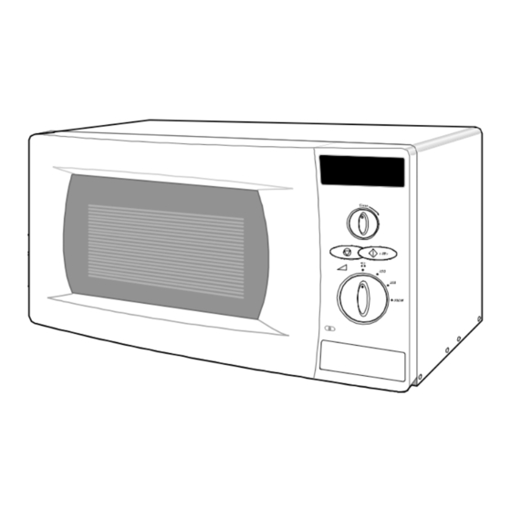
Page 10: Your New Microwave Oven
3. Your New Microwave Oven 3-1. Checking Parts and Setting Up Your Microwave Oven Setting Up Your Microwave Oven Checking Parts Unpack your microwave oven and check to make sure Once connected to the power supply the that you have all the parts shown here. If any parts is display on your oven will show: missing or broken, call your dealer. - Page 11 3. Your New Microwave Oven (Continued) 3-2. Control Panel - 10 -...
-
Page 12: Operation
4. Operation Setting Cooking Times Important Remark This following procedure explains how to cook or reheat Voltage supply of the microwave oven is limited to food. Always check your cooking settings before leaving protect the safety of product and vehicle the oven unattended. -
Page 13: Using The Start +30 S Button
4. Operation (Continued) Error Codes Using the Start +30 s Button This is a ONE TOUCH COOK pad. Error Items Code Cause/Remedy By touching the pad once, you can start heating instantly Low Batt. Voltage/Check the for 30 seconds. Low Voltage Batt. -
Page 14: Disassembly And Reassembly
5. Disassembly and Reassembly 5-1. Replacement of Magnetron, Motor Assembly and Lamp Remove the magnetron including the shield case, permanent magnet, choke coils and capacitors (all of which are contained in one assembly). 1. Disconnect all lead wires from the magnetron and lamp. 2. -
Page 15: Replacement Of Fuse
5. Disassembly and Reassembly (continued) 5-2. Reassembly After replacement of the defective component parts of the door, reassemble it and follow the instructions below for proper installation and adjustment so as to prevent an excessive microwave leakage. 1. When mounting the door to the oven, be sure to adjust the door parallel to the bottom line of the oven face plate by moving the upper hinge and lower hinge in the direction necessary for proper alignment. -
Page 16: Alignment And Adjustments
6. Alignment and Adjustments 6-1 Low Voltage Transformer 1. The low voltage transformer is located on the control circuit board. 2. Remove the low voltage transformer from the PCB Ass’y and check continuity. 3. Normal resistor reading is shown in the table. Resistance Terminals SLV-4300B... -
Page 17: High Voltage
6. Alignment and Adjustments (continued) Diode 6-4. High Voltage 1. Isolate the diode from the Inverter-P.C.B by disconnecting its leads. 2. With the ohm-meter set at the highest resistance scale, measure across the diode terminals. Reverse the meter leads and read the resistance. A meter with 6V, 9V or higher voltage batteries should be used to check the front-to back resistance of the diode (otherwise an infinite resistance may be read in both directions). -
Page 18: Troubleshooting
Troubleshooting PRECAUTION 1. Check ground before checking for trouble. 2. Be careful of the high voltage circuit 3. Discharge the high voltage capacitor. 4. When checking the continuity of the switches or transformer, disconnect lead wires from these parts and then check continuity without the power source on. -
Page 19: Electrical Malfunction
7. Troubleshooting (Continued) 7-2 Electrical Malfunction SYMPTOM CAUSE CORRECTIONS Oven is dead 1. Open or loose lead wire harness Check wire harness Main Fuse is OK. 2. Open thermal cutout switch Check magnetron or cavity thermal No display and no operation (magnetron, cavity) cutout switch is defective. -
Page 20: Exploded Views And Parts List
8. Exploded Views and Parts List 8-1 Exploded Views - 19 -... -
Page 21: Main Parts List
DE31-10154A MOTOR-SYNCHRONOUS M2HJ49ZR02,ST-16,50/60HZ,- DE71-00152A COVER-MGT MW630WA,PP,T2,W54,L129,-,GE-WHT,NC2000 DE39-00323A WIRE HARNESS-DC 6 DE6612,12/24V 31KHZ,-,-,-,-,-,-,-,-,-,-,-,-,-,- ASSY CONTROL-BOX DC24V,DE6612N,D-GRY/G3328,0.6CUFT/DC-MWO S.N.A DE94-00535B ASSY DOOR DE6612N/DC24VOLT,D-GRY/G3328,SAMSUNG DE71-00063A COVER-CONNECTOR RUBBER DE6612,RUBBER,T2.5,-,-,-,-,-,06CUFT DC-MWO DE97-00268A ASSY-POWER CONNECTOR DE6612,DC-24V,DC-MWO,- DE61-00303A BRACKET-MOUNTING HINGE DE6612/24V,SECC,T1.2,-,-,-,HINGE-UPP DE61-00213B BRACKET-L/R DC-MWO,SECC ,T1.6,-,-,BLACK,06/DC-MWO DE97-00189A ASSY-PACKING SCREW... -
Page 22: Door Parts List
8. Exploded Views and Parts List (Continued) 8-4 Door Parts List Code No. Description Specification Q’ty Remark DE64-00298B DOOR-A DC-MWO,ABS(HR0370D),-,-,-,-,D-GRY(G3328),0.6CF DE63-00040A SCREEN-DOOR CLEAR,NC06,-,T0.25,W150,-,L284,-, DOOR-A DE94-00532A ASSY DOOR-E(COATING) DE6612N,BLK,0.6-DC MWO DE64-00182A DOOR-C MW630WA,PP,-,BLK,-,0.6CUFT,NC2000 DE64-00221A FILM-DOOR -,-,T0.13,W212*L102,-,-,-,NC06 DOOR-E DE60-00018A SPACER-DOOR MD4300,TEFRON+NITT02000,-,-,-,WHT,T0.8+0.15,-,- DOOR-E DE64-00217A DOOR-KEY NC2000(0.6),POM,-,BLK,-,-,BUTTON-TYPE... - Page 23 8. Exploded Views and Parts List (Continued) 8-7 Screw Parts List Code No. Description Specification Q’ty Remark 6011-001446 BOLT-FLANGE M4,L10,ZPC(BLK),SWRCH18A,- MOUNT-HINGE 6011-001446 BOLT-FLANGE M4,L10,ZPC(BLK),SWRCH18A,- MOUNT-MGT DE60-20063A BOLT-FLANGE M4,10,ZPC3,YEL,MSWR,-,-,-,- HIN-LOW DE60-20063A BOLT-FLANGE M4,10,ZPC3,YEL,MSWR,-,-,-,- HIN-UPP DE60-30016B NUT-FLANGE M4,MSWR10,FEFN,-,-,-,-,-,- H-TRAY 6021-001037 NUT-HEXAGON 2C,M5,NI PLT,BRASS SUB-PCB 6021-001128 NUT-HEXAGON...
- Page 24 9. P.C.B Circuit Diagrams and Parts List 9-1. Main P.C.B Circuit Diagrams - 23-...
- Page 25 9. P.C.B Circuit Diagrams and Parts List (Continued) 9-2. Main P.C.B Parts List Code No. Description Specification Q’ty Remark 0503-001036 TR-DARLINGTON KTD1413,NPN,25W,TO-220IS,ST,2000-15000 TR05,06 1203-000259 IC-POSI.FIXED REG. 7818,TO-220,3P,-,PLASTIC,17.3/ 3501-001155 RELAY-MINIATURE 24VDC,200MW,3000MA,1FORMA,10MS,10MS RY01~03 DE07-00023A LED DISPLAY CSQ-424AG,18MM,4DISP,-,-,45.2*22.38*22.0,YEL/GRN,100M LED1 DE09-00108A IC MICOM TMP87PM14F,OTP-32K,QFP,8BIT-64PIN,-,-,-,- IC01 DE13-20014A IC-VOLT REGU...
- Page 26 9. P.C.B Circuit Diagrams and Parts List (Continued) 9-3. Inverter P.C.B Circuit Diagram - 25 -...
- Page 27 9. P.C.B Circuit Diagrams and Parts List (Continued) 9-4. Drive P.C.B Circuit Diagram - 26 -...
- Page 28 9. P.C.B Circuit Diagrams and Parts List (Continued) 9-5. Monitor P.C.B Parts List Code No. Description Specification Q’ty Remark 3601-001094 FUSE-CARTRIDGE 250V,5A,FAST-ACTING DE47-40024A HOLDER-FUSE FH-51H,7.5A 9-6. Drive P.C.B Parts List Code No. Description Specification Q’ty Remark 1003-001394 IC-GATE DRIVER IR2153,DIP,8P,260MIL - 27 -...
-
Page 29: Wiring Diagrams And Operating Sequence
10. Wiring Diagrams and Operating Sequence 10-1. Wiring Diagram - 28 -... -
Page 30: Description Of Operating Sequence
10. Wiring Diagrams and Operating Sequence (continued) 10-2. Description of Operating Sequence When oven is started, initial operating status is shown below figure. Test point WAVE FORM in circuit diagram Fan relay Lamp relay Power relay ƒ= 250Hz PWM output ƒ=27KHz Out 1 ƒ=27KHz...