
Related Manuals for Toro 74766


Summary of Contents for Toro 74766
- Page 1 Form No. 3409-414 Rev A TimeCutter MX 4200 Riding ® Mower Model No. 74766—Serial No. 400000000 and Up *3409-414* A Register at www.Toro.com. Original Instructions (EN)
- Page 2 Write the numbers in the space provided. Important: If you are using a machine with a Toro engine above 1500 m (5,000 ft) for a continuous period, ensure that the High Altitude Kit has been installed so that the engine meets CARB/EPA emission regulations.
-
Page 3: Table Of Contents
Contents Model No. Safety ................4 Serial No. General Safety............4 Slope Indicator ............5 Safety and Instructional Decals ......... 6 This manual identifies potential hazards and has safety Product Overview ............11 messages identified by the safety-alert symbol (Figure Controls ...............11 which signals a hazard that may cause serious injury or death Before Operation ............13 if you do not follow the recommended precautions. -
Page 4: Safety
Safety Drive System Maintenance .........38 Checking the Tire Pressure ........38 Releasing the Electric Brake ........38 This machine has been designed in accordance with ANSI Mower Maintenance ...........39 B71.1-2012. Servicing the Cutting Blades........39 Leveling the Mower Deck ........41 Removing the Mower Deck ........43 General Safety Installing the Mower ..........44 Replacing the Grass Deflector ........44... -
Page 5: Slope Indicator
Slope Indicator G011841 g011841 Figure 4 This page may be copied for personal use. 1. The maximum slope you can safely operate the machine on is 15 degrees. Use the slope chart to determine the degree of slope of hills before operating. Do not operate this machine on a slope greater than 15 degrees. Fold along the appropriate line to match the recommended slope. -
Page 6: Safety And Instructional Decals
Safety and Instructional Decals Safety decals and instructions are easily visible to the operator and are located near any area of potential danger. Replace any decal that is damaged or missing. decal93-7009 93-7009 1. Warning—do not operate the mower with the deflector up or removed;... - Page 7 decalbatterysymbols Battery Symbols Some or all of these symbols are on your battery. 1. Explosion hazard 6. Keep bystanders a safe distance away from the battery. 7. Wear eye protection; 2. No fire, open flame, or smoking explosive gases can cause blindness and other injuries.
- Page 8 decal132-0872 132-0872 1. Thrown object 3. Severing hazard of hand hazard—keep bystanders or foot—keep away from away from the machine. moving parts. 2. Thrown object hazard, 4. Entanglement raised baffle—do not hazard—keep away operate the machine with from moving parts; keep an open deck;...
- Page 9 decal121-0772 121-0772 1. Fast 4. Choke 2. Continuous-variable setting 5. Power takeoff (PTO), Blade-control switch 3. Slow...
- Page 10 decal132-0869 132-0869 This machine complies with the industry standard stability test in the static lateral and longitudinal tests with the maximum recommended slope indicated on the decal. Review the instructions for operating the machine on slopes in the Operator's Manual and the conditions in which the machine is being operated to determine whether the machine can be operated in the conditions on that day and at that site.
-
Page 11: Product Overview
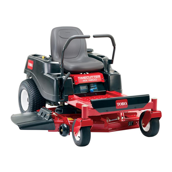
Product Overview g028166 g028166 Figure 5 1. Deflector 4. Height-of-cut lever 7. Footrest 10. Engine 2. Rear drive wheel 5. Operator seat 8. Fuel-tank cap 11. Engine guard 3. Motion-control levers 6. Smart Speed™ lever 9. Control panel 12. Front caster wheel Controls Ignition Switch Become familiar with all the controls in... - Page 12 A selection of Toro approved attachments and accessories is available for use with the machine to enhance and expand its capabilities. Contact your Authorized Service Dealer or Distributor or go to www.Toro.com for a list of all approved attachments and accessories. g014521 Figure 7 1.
-
Page 13: Before Operation
Operation • Remove the equipment from the truck or trailer and refuel it while it is on the ground. If this is not possible, then refuel from a portable container rather than a Note: Determine the left and right sides of the machine fuel-dispenser nozzle. -
Page 14: Using Stabilizer/Conditioner
Using Stabilizer/Conditioner Use a fuel stabilizer/conditioner in the machine to provide the following benefits: • Keeps fuel fresh during storage of 90 days or less (drain the fuel tank when storing the machine for more than 90 days) • Cleans the engine while it runs •... -
Page 15: Using The Safety-Interlock System
Using the Safety-Interlock DANGER System Wheels dropping over edges can cause rollovers, which may result in serious injury, death, or drowning. WARNING Do not operate the machine near drop-offs. If the safety-interlock switches are disconnected or damaged, the machine could operate unexpectedly, causing personal injury. -
Page 16: Positioning The Seat
Positioning the Seat Testing the Safety-Interlock System The seat can move forward and backward. Position the seat where you have the best control of the machine and are most Test the safety-interlock system before you use the machine comfortable (Figure 12). -
Page 17: During Operation
During Operation Adjusting the Tilt You can adjust the motion-control levers forward or rearward During Operation Safety for your comfort. 1. Loosen the upper bolt holding the control lever to the control-arm shaft. General Safety 2. Loosen the lower bolt just enough to pivot the control •... -
Page 18: Operating The Mower Blade-Control Switch (Pto)
Do not change the governor speed or overspeed the Engaging the Blade-Control engine. Switch (PTO) • Use accessories and attachments approved by Toro only. Slope Safety • Establish your own procedures and rules for operating on slopes. These procedures must include surveying the site to determine which slopes are safe for machine operation. -
Page 19: Operating The Throttle
Operating the Throttle You can move the throttle control between the F positions (Figure 17). Always use the F position when turning on the mower deck with the blade-control switch (PTO). g187517 Figure 17 G008959 g008959 Figure 18 1. O position 2. -
Page 20: Starting And Shutting Off The Engine
Starting and Shutting Off Using the Motion-Control the Engine Levers Starting the Engine Note: A warm or hot engine may not require choking. Important: Do not engage the starter for more than 5 seconds at a time. Engaging the starter motor for more than 5 seconds can damage the starter motor. - Page 21 Driving Forward Using the Smart Speed Control System Note: Always use caution when backing up and turning. The Smart Speed Control-System lever, located below the 1. Move the levers to the center, unlocked position. operating position (Figure 24), gives the operator a choice 2.
-
Page 22: Stopping The Machine
Adjusting the Height of Cut This is the medium speed. The suggested uses for this speed Note: The transport position is the highest height-of-cut are as follows: position at 115 mm (4-1/2 inches) as shown in Figure • Bagging • Mulching This is the fastest speed. -
Page 23: Using The Side Discharge
Operating Tips Using the Fast Throttle Setting For best mowing and maximum air circulation, operate the engine at the F position. Air is required to thoroughly cut G010233 grass clippings, so do not set the height-of-cut so low as to totally surround the mower in uncut grass. -
Page 24: After Operation
Use full-width ramps for loading the machine into a the blades as necessary. If a blade is damaged or worn, replace trailer or truck. it immediately with a genuine Toro replacement blade. • Tie the machine down securely using straps, chains, cable, or ropes. -
Page 25: Transporting The Machine
Transporting the Machine Use a heavy-duty trailer or truck to transport the machine. Ensure that the trailer or truck has all necessary brakes, lighting, and marking as required by law. Please carefully read all the safety instructions. Knowing this information could help you, your family, pets, or bystanders avoid injury. -
Page 26: Loading The Machine
Loading the Machine Use extreme caution when loading or unloading machines onto a trailer or a truck. Use a full-width ramp that is wider than the machine for this procedure. Back the machine up the ramp and drive it forward down the ramp (Figure 29). -
Page 27: Maintenance
Maintenance Note: Determine the left and right sides of the machine from the normal operating position. Recommended Maintenance Schedule(s) Maintenance Service Maintenance Procedure Interval • Change the engine oil. After the first 5 hours • Check the safety-interlock system. • Check the air cleaner for dirty, loose, or damaged parts. •... -
Page 28: Pre-Maintenance Procedures
Check their proper operation regularly. • To ensure optimum performance and continued safety certification of the machine, use only genuine Toro replacement parts and accessories. Replacement parts and accessories made by other manufacturers could be dangerous, and such use could void the product warranty. -
Page 29: Lubrication
Lubrication Engine Maintenance Engine Safety Greasing the Bearings Shut off the engine before checking the oil or adding oil to Service Interval: Every 25 hours—Grease all lubrication the crankcase. points. Grease Type: No. 2 lithium grease Servicing the Air Cleaner 1. -
Page 30: Servicing The Engine Oil
Servicing the Engine Oil 7. Remove the foam element from the paper element (Figure 34). Oil Type: Detergent oil (API service SF, SG, SH, SJ, or SL) Crankcase Capacity: with filter—2.4 L (81.2 fl oz) Viscosity: See the table below. SAE 30 SAE 5W -30, 10W -30... - Page 31 Changing the Engine Oil and Oil Filter Service Interval: After the first 5 hours/After the first month (whichever comes first)—Change the engine oil. Every 100 hours/Yearly (whichever comes first)—Change the engine oil and filter (more often in dusty, dirty conditions). Note: Change the engine-oil filter more frequently when operating conditions are extremely dusty or sandy.
- Page 32 5. Change the engine-oil filter (Figure 38). Note: Ensure that the oil-filter gasket touches the engine and then turn the filter an extra 3/4 turn. g027799 g027799 g027477 g027477 Figure 38 6. Slowly pour approximately 80% of the specified oil into the filler tube and slowly add the additional oil to bring it to the Full mark (Figure...
-
Page 33: Servicing The Spark Plug
Removing the Spark Plug 1. Disengage the PTO and move the motion-control levers to the P position. 2. Shut off the engine, remove the key, and wait for all moving parts to stop before leaving the operating position. g027478 g027478 Figure 40 Note: Due to the deep recess around the spark plug, blowing out the cavity with compressed air is the most... -
Page 34: Cleaning The Cooling System
Installing the Spark Plug Tighten the spark plug(s) to 25 to 30 N∙m (18.5 to 22.1 ft-lb). 25-30 N-m 18.5-22.1 ft-lb g027960 g027960 Figure 42 Cleaning the Cooling System Clean the air intake screen from grass and debris before each use. -
Page 35: Fuel System Maintenance
Fuel System Maintenance DANGER In certain conditions, fuel is extremely flammable g027939 and highly explosive. A fire or explosion from fuel g027939 can burn you, others, and can damage property. • Perform any fuel-related maintenance when the engine is cold. Do this outdoors in an open area. Wipe up any fuel that spills. -
Page 36: Electrical System Maintenance
Electrical System 2. Move the motion-control levers outward to the P position, shut off the engine, remove the key, and Maintenance wait for all moving parts to stop before leaving the operating position. 3. Raise the seat to access the battery. Electrical System Safety 4. -
Page 37: Servicing The Fuses
Servicing the Fuses Charging the Battery Service Interval: Before storage—Charge the battery and The electrical system is protected by fuses. It requires disconnect the battery cables. no maintenance; however, if a fuse blows, check the component/circuit for a malfunction or short. 1. -
Page 38: Drive System Maintenance
Drive System Releasing the Electric Brake Maintenance You can manually release the electric brake by rotating the link arms forward. Once the electric brake is energized, the Checking the Tire Pressure brake resets. Service Interval: Every 25 hours—Check tire pressure. 1. -
Page 39: Mower Maintenance
Mower Maintenance Servicing the Cutting Blades To ensure a superior quality of cut, keep the blades sharp. For convenient sharpening and replacement, keep extra blades on hand. g006530 Figure 49 Blade Safety 1. Cutting edge 3. Wear/slot forming 2. Curved area 4. - Page 40 Note: If a bent blade is replaced with a new blade, and the dimension obtained continues to exceed 3 mm (1/8 inch), the blade spindle could be bent. Contact an Authorized Toro Dealer for service. B. If the variance is within constraints, move to the next blade.
-
Page 41: Leveling The Mower Deck
Removing the Blades Replace the blades if they hit a solid object, or if the blade is out of balance or bent. g000553 1. Hold the blade end using a rag or thickly padded glove. Figure 56 2. Remove the blade bolt, curved washer, and blade from 1. - Page 42 9. Check the side-to-side adjustments again. Repeat this procedure until the measurements are correct. 10. Continue leveling the mower deck by checking the front-to-rear blade slope; refer to Adjusting the G009682 Front-to-Rear Blade Slope (page 42). Adjusting the Front-to-Rear Blade Slope Check the front-to-rear blade level any time you install the mower.
-
Page 43: Removing The Mower Deck
Removing the Mower Deck C. To lower the front of the mower, loosen the adjustment nut. 1. Park the machine on a level surface and disengage the D. After adjustment, check the front-to-rear slope blade-control switch. again, continue adjusting the nut until the front 2. -
Page 44: Installing The Mower
Replacing the Grass Deflector Service Interval: Before each use or daily—Inspect the grass deflector for damage. WARNING An uncovered discharge opening could allow the lawn mower to throw objects toward you or bystanders, resulting in serious injury. Also, contact with the blade could occur. Never operate the machine without the grass deflector, the discharge cover, or the grass-collection system in place. - Page 45 g017618 g017618 Figure 64 1. Rod and spring assembly 3. Rod, short end, moved installed behind the mower bracket 2. Loop end of the spring 4. Short end, retained by installed into the notch in mower bracket. the deflector bracket 7.
-
Page 46: Mower Belt Maintenance
65). g188324 Figure 65 1. Cover 2. Screw 5. Using a spring-removal tool (Toro Part No. 92-5771), remove the idler spring from the deck hook to remove tension on the idler pulley, and roll the belt off the pulleys (Figure 66). -
Page 47: Cleaning
Cleaning 8. Turn the water off and remove the coupling from the washout fitting. Note: If the mower is not clean after 1 washing, soak Washing the Underside of it and let it stand for 30 minutes. Then, repeat the the Mower process. -
Page 48: Storage
Storage spark plug(s) removed from the engine, pour 30 ml (2 tablespoons) of engine oil into the spark plug hole. Use the starter to crank the engine and distribute the Cleaning and Storage oil inside the cylinder. Install the spark plug(s). Do not install the wire on the spark plug(s). -
Page 49: Troubleshooting
Troubleshooting Problem Possible Cause Corrective Action The engine overheats. 1. The engine load is excessive. 1. Reduce the ground speed. 2. The oil level in the crankcase is low. 2. Add oil to the crankcase. 3. The cooling fins and air passages 3. - Page 50 Problem Possible Cause Corrective Action There is an abnormal vibration. 1. The engine-mounting bolts are loose. 1. Tighten the engine-mounting bolts. 2. The engine pulley, idler pulley, or blade 2. Tighten the appropriate pulley. pulley is loose. 3. The engine pulley is damaged. 3.
-
Page 51: Schematics
Schematics g028022 Electrical Diagram (Rev. A) - Page 52 Countries Other than the United States or Canada This warranty is not valid in Mexico. Customers who have purchased Toro products outside the United States or Canada should contact their Toro Distributor (Dealer) to obtain guarantee policies for your country, province, or state. If for any reason you are dissatisfied with your Distributor's service or have difficulty obtaining guarantee information, contact the Toro importer.