Advertisement
Quick Links
Q ui c k Sta r t G u id e
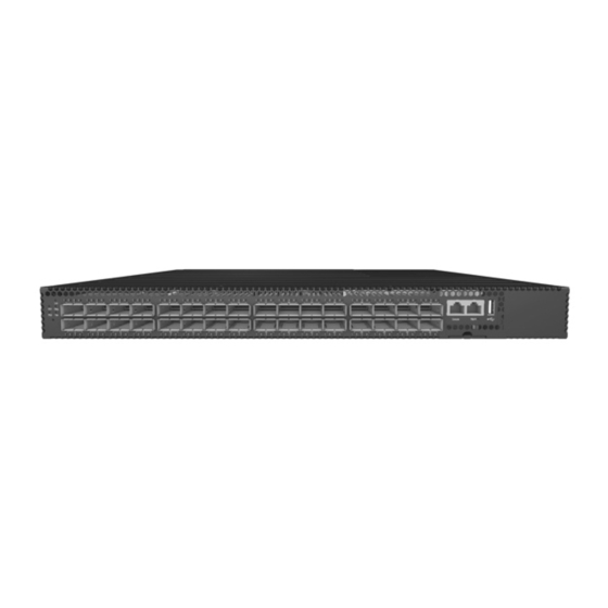
32-Port 40G Data Center Switch
HP Altoline 6712 32QSFP+ x86 Switch Series
1. Unpack the Switch and Check Contents
Rack Mounting Kit—two brackets and eight screws
Power Cord—Country-specific power cord(s)
Console Cable—RJ-45 to DB-9
Documentation—Quick Start Guide (this document)
and Safety and Regulatory Information
Note:
The switch has the Open Network Installer
Environment (ONIE) software pre-loaded, but no switch
software image pre-loaded.
Caution:
The switch includes plug-in power supply and
fan tray modules that are installed into its chassis. All
installed modules must have a matching airflow direction.
That is, all modules must have a front-to-back (F2B) airflow
direction, or all modules must have a back-to-front (B2F)
airflow direction. The airflow direction of fan tray modules
is indicated by text printed on the modules.
2. Mount the Switch
1
Attach the brackets to the switch.
2
Use the screws supplied with the rack to secure the switch in
the rack.
Caution:
Installing the switch in a rack requires two
people. One person should position the switch in the rack,
while the other secures it using the rack screws.
HP Altoline 6712 32QSFP+
x86 Switch Series
40G Data Center Switch
1
2
3. Connect Power
1
2
1
Install one or two universal AC PSUs in the switch that have
the same airflow direction as the installed fan trays.
Note:
The airflow direction of fan tray modules is indicated
by text printed on the modules.
2
Connect an external AC power source to the modules.
3
Use the included power cable ties to secure the power cord
connections to the switch.
4. Verify Switch Operation
1
1
Verify basic switch operation by checking the system LEDs.
When operating normally, the PS1/PS2, Diag, and Fan LEDs
should all be on green.
5. Perform Initial System Boot
1
If the network operating system (NOS) installer is located on
a network server, first connect the RJ-45 Management
(Mgmt) port to the network using Category 5, 5e or better
twisted-pair cable. (Not required if the NOS installer is
located on attached storage.)
2
Boot the switch. Wait for the ONIE software to locate and
execute the NOS installer, and then wait for the installer to
load the NOS software image.
Subsequent switch boots will bypass ONIE and directly run
the NOS software.
Note:
Refer to NOS installer and NOS documentation for
details on software location options and set up for ONIE.
– 1 –
E042015-CS-R01
Advertisement

Related Manuals for HP Altoline 6712 32QSFP+ Series


Summary of Contents for HP Altoline 6712 32QSFP+ Series
- Page 1 Q ui c k Sta r t G u id e 32-Port 40G Data Center Switch HP Altoline 6712 32QSFP+ x86 Switch Series 1. Unpack the Switch and Check Contents 3. Connect Power HP Altoline 6712 32QSFP+ x86 Switch Series 40G Data Center Switch Rack Mounting Kit—two brackets and eight screws...
- Page 2 Quick Start Guide 6. Connect Network Cables Hardware Specifications Chassis Size (WxDxH) 438.4 x 515 x 43.5 mm (17.26 x 20.28 x 1.71 inch) Weight 9.65 kg (21.27 lb), with two installed PSUs Temperature Operating: 0° C to 40° C (32° F to 104° F) Storage: -40°...
- Page 3 7.6 cm (3inches) for cooling. Hewlett-Packard Company 3000 Hanover Street, Palo Alto, California, 94304U.S.A. For additional safety and regulatory information, and switch recycling information, refer to the safety and regulatory documentation on the HP website at www.hp.com/support/Safety-Compliance-EnterpriseProducts Power Cords Argentina 8121-0729...
- Page 4 “make” files contained in the product and used to build the product along with instructions on modifying and building the product are available from HP. This offer is valid to anyone in receipt of this information and shall expire three years following the date of the final distribution or support of this product version by Hewlett-Packard Company.