Table of Contents
Advertisement
Quick Links
READ THIS MANUAL CAREFULLY!
It contains important safety information.
LIRE ATTENTIVEMENT CE MANUEL!
Il comprend d'importantes informations de sécurité.
¡LEA ESTE MANUAL ATENTAMENTE!
Contiene indicaciones importantes acerca de la seguridad.
MANUEL DU PROPRIÉTAIRE
MANUAL DEL PROPIETARIO
OWNER'S MANUAL
YFM700R
BCX-F8199-60
Advertisement
Table of Contents
Troubleshooting

Related Manuals for Yamaha YFM700R


Summary of Contents for Yamaha YFM700R
- Page 1 READ THIS MANUAL CAREFULLY! It contains important safety information. LIRE ATTENTIVEMENT CE MANUEL! Il comprend d’importantes informations de sécurité. ¡LEA ESTE MANUAL ATENTAMENTE! Contiene indicaciones importantes acerca de la seguridad. OWNER’S MANUAL MANUEL DU PROPRIÉTAIRE MANUAL DEL PROPIETARIO YFM700R BCX-F8199-60...
- Page 2 Original instructions Notice originale Manual original PRINTED IN USA 2019.05-0.4×1 CR (E,F,S)
- Page 3 READ THIS MANUAL CAREFULLY! It contains important safety information. OWNER’S MANUAL YFM700R WARNING This ATV should not be ridden by anyone under 16 years of age. BCX-F8199-60-E0...
- Page 4 EBU28981 Read this manual carefully before operating this vehicle. This manual should stay with this ve- hicle if it is sold.
- Page 5 INTRODUCTION EBU17323 Congratulations on your purchase of the Yamaha YFM700R. This ATV represents the result of many years of Yamaha experience in the production of fine sporting, touring, and pacesetting racing machines. With the purchase of this Yamaha, you can now appreciate the high degree of craftsmanship and reliability that have made Yamaha a leader in these fields.
- Page 6 EBU17331 IMPORTANT MANUAL INFORMATION EBU17344 FAILURE TO FOLLOW THE WARNINGS CONTAINED IN THIS MANUAL CAN RESULT IN SERIOUS IN- JURY OR DEATH. Particularly important information is distinguished in this manual by the following notations: This is the safety alert symbol. It is used to alert you to potential per- sonal injury hazards.
- Page 7 Please check your local riding laws and regulations before operating this ATV. EBU17411 YFM700R OWNER’S MANUAL ©2020 by Yamaha Motor Co., Ltd. 1st edition, March 2019 All rights reserved. Any reprinting or unauthorized use without the written permission of Yamaha Motor Co., Ltd.
-
Page 8: Table Of Contents
EBU17421 TABLE OF CONTENTS VEHICLE IDENTIFICATION ......1-1 Parking brake lever ........5-7 Identification numbers ........1-1 Shift pedal........... 5-8 Reverse knob “REV”........5-9 LOCATION OF THE WARNING AND Fuel tank cap ..........5-9 SPECIFICATION LABELS ......2-1 Fuel ............5-10 Seat ............5-12 SAFETY INFORMATION ........3-1 Front shock absorbers (For models equipped with only adjustable spring... - Page 9 Throttle lever ..........6-5 RIDING OVER ROUGH TERRAIN..... 8-20 Drive chain ..........6-5 SLIDING AND SKIDDING ......8-20 Tires ............6-5 WHAT TO DO IF........8-21 Chassis fasteners........6-7 Instruments, lights and switches ....6-7 PERIODIC MAINTENANCE AND ADJUSTMENT ..........9-1 OPERATION ...........
- Page 10 Checking the front brake lever free play ...9-35 Troubleshooting........9-55 Checking the brake pedal height ....9-35 Troubleshooting charts......9-56 Adjusting the parking brake free play ..9-36 Brake light switches ........9-37 CLEANING AND STORAGE......10-1 Adjusting the clutch lever free play ...9-38 Cleaning............
-
Page 11: Vehicle Identification
EBU38860 VEHICLE IDENTIFICATION EBU28205 Identification numbers Record the vehicle identification number and model label information in the spaces provided below. VEHICLE IDENTIFICATION NUMBER: MODEL LABEL INFORMATION: 1. Vehicle identification number EBU26053 Model label The model label is affixed at the location shown. EBU26032 Vehicle identification number The vehicle identification number is stamped into... - Page 12 1. Model label Your specific model can be identified by checking the model type code found on the model label. * * * * - * * * 1. Model type code 2. Production code 3. Color code...
-
Page 13: Location Of The Warning And Specification Labels
Read and understand all of the labels on your ATV. These labels contain important information for safe and proper operation. Never remove any labels from your ATV. If a label becomes difficult to read or comes off, request a re- placement label from your Yamaha dealer. - Page 14 YAMAHA MOTOR CO., LTD. SHIZUOKA JAPAN YAMAHA 4GB-2155A-00 B16-F811S-00 1HP-F2259-21 B4F-F817K-00 YAMAHA 1HP-F811R-00...
- Page 15 YAMAHA 3C2-F816P-00 YAMAHA 1P0-F816R-00 27.5 kPa 27.5 kPa 0.275 kgf/cm² 0.275 kgf/cm² 4.0 psi 4.0 psi 1PE-F816M-M0...
- Page 16 Familiarize yourself with the following pictograms and read the explanatory text, then make sure to check the pictograms that apply to your model. Read the Owner’s manual. Use from 16 years old. Operating this ATV if you are under the age of 16 increases your chance of severe injury or death.
- Page 17 This unit contains high-pressure nitrogen Measure the tire pressure when the tires are gas. cold. Mishandling can cause an explosion. Do not incinerate, puncture or open. EN228 fuel identification mark. Adjust the tire pressure. Gasoline of ethanol 5% or less can be used. Improper tire pressure can cause loss of control.
-
Page 18: Safety Information
EBU17432 SAFETY INFORMATION SAFETY INFORMATION Never allow a child under age 16 to operate an EBU26686 ATV without adult supervision, and never allow AN ATV IS NOT A TOY AND CAN BE HAZARD- continued use of an ATV by a child if he or she OUS TO OPERATE. - Page 19 Never operate at speeds too fast for your skills Never operate the ATV on hills too steep for the or the riding conditions. Always go at a speed ATV or for your abilities. Practice on smaller hills that is proper for the terrain, visibility, operating before attempting larger hills.
- Page 20 Never operate an ATV in fast flowing water or in technique described in this manual on level ground. Avoid crossing the side of a steep hill if water deeper than that recommended in this possible. manual. Remember that wet brakes may have ...
- Page 21 Never maintain an ATV without proper knowl- vehicle. If the vehicle is in safe operating con- edge. Contact an authorized ATV dealer to in- dition and you can safely operate it, restart it form you on basic ATV maintenance. Certain and ride gently back to camp or other known maintenance can only be carried out by certified location where you can receive medical at-...
- Page 22 While you may find aftermarket products similar in of the operator and may limit control ability, design and quality to genuine Yamaha accesso- therefore, such accessories are not recom- ries, recognize that some aftermarket accessories mended.
- Page 23 Do not run engine in poorly ventilated or par- gerous loss of lights or engine power. Also, the battery tends to discharge more quickly if elec- tially enclosed areas such as barns, garages, trical accessories are added. or carports. ...
-
Page 24: Description
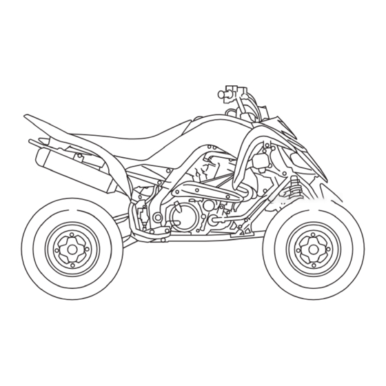
EBU17681 DESCRIPTION EBU17691 EBU17701 Left view Right view 3 4 5 6 7 10 9 1. Engine oil tank 1. Muffler 2. Coolant reservoir 2. Spark arrester 3. Fuel tank cap 3. Air filter 4. Idle adjusting screw 4. Rear brake fluid reservoir 5. -
Page 25: Controls And Instruments
EBU17715 Controls and instruments 1. Clutch lever 2. Parking brake lever 3. Main switch 4. Front brake fluid reservoir 5. Brake lever 6. Throttle lever 7. Reverse knob 8. Handlebar switches... -
Page 26: Instrument And Control Functions
EBU17739 INSTRUMENT AND CONTROL FUNCTIONS EBU29913 EBU26699 Main switch Indicator lights and warning lights 1. Main switch 1. Fuel level warning light “ ” 2. Engine trouble warning light “ ” “ ” (on) 3. Coolant temperature warning light “ ”... - Page 27 “ ” (on), or if the warning The electrical circuit of the warning light can be light remains on, have a Yamaha dealer check the checked by setting the engine stop switch to “ ”...
-
Page 28: Self-Diagnosis Device
This warning light comes on or flashes when an To prevent engine damage, be sure to consult electrical circuit monitoring the engine is not work- a Yamaha dealer as soon as possible if this oc- ing correctly. When this occurs, have a Yamaha curs. -
Page 29: Throttle Lever
starter will not have enough power to crank the EBU18081 Engine stop switch “ ” engine. If this should happen, remove the bat- Set this switch to “ ” before starting the engine. tery and recharge it. (See page 9-47.) The engine stop switch controls the ignition and stops the engine when it is running. -
Page 30: Speed Limiter
the adjusting screw in direction (b). Do not EBU18325 Speed limiter turn the adjusting screw out more than 12 mm (0.47 in) or the throttle cable could be damaged. Always make sure the throttle lever free play is adjusted to 2.0–4.0 mm (0.08– 0.16 in). -
Page 31: Brake Lever
The clutch lever is located on the left side of the For models equipped with an adjustable brake handlebar. To disengage the clutch, pull the clutch lever lever toward the handlebar grip. To engage the clutch, release the lever. The lever should be pulled rapidly and released slowly for smooth clutch operation. -
Page 32: Brake Pedal
EBU18434 Brake pedal 1. Parking brake lever (locked position) 1. Brake pedal The brake pedal is located on the right side of the ATV. To apply the rear brake, push down on the brake pedal. EBU18521 Parking brake lever Use the parking brake before starting the engine or parking the ATV, especially on a slope. -
Page 33: Shift Pedal
EWB00221 EBU18542 Shift pedal WARNING Always set the parking brake before starting the engine. The ATV could start moving un- expectedly if the parking brake is not ap- plied. This could cause loss of control or a collision. Always be sure you have released the park- ing brake before you begin to ride. -
Page 34: Reverse Knob "Rev
EBU18643 EBU37980 Reverse knob “REV” Fuel tank cap 1. Reverse knob “REV” 1. Fuel tank cap The reverse knob is used when shifting into re- Remove the fuel tank cap by turning it counter- verse. (See page 7-4.) clockwise. EWB02522 WARNING Gasoline and gasoline vapors are extremely flammable. -
Page 35: Fuel
of sparks, open flames, or other sources of 3. Wipe up any spilled fuel immediately. NOTICE: Immediately wipe off spilled fuel ignition such as the pilot lights of water heat- ers and clothes dryers. with a clean, dry, soft cloth, since fuel may 2. - Page 36 About the recommended fuel Recommended fuel: This model’s engine has been designed to use Regular unleaded gasoline only regular unleaded gasoline. The research octane Fuel tank capacity: number should be 95 or higher. If knocking or 11 L (2.9 US gal, 2.4 Imp.gal) pinging occurs, try a gasoline of a different brand Fuel reserve amount: or higher octane.
-
Page 37: Seat
To install the seat EBU29892 Seat To remove the seat 1. Slot 2. Projection 3. Seat holder 1. Seat lock lever Fit the slot in the seat onto the projection on the Push the seat lock lever backward and pull up the fuel tank, insert the projection on the front of the seat at the rear. -
Page 38: Front Shock Absorbers (For Models Equipped With Only Adjustable Spring Preload)
2. Position indicator cident. Adjust the spring preload as follows. A special wrench can be obtained at a Yamaha Turn the spring preload adjusting ring in direction dealer to make this adjustment. (a) to increase the spring preload and thereby... -
Page 39: Front Shock Absorbers (For Models Equipped With Adjustable Spring Preload And Damping Force)
Cylinder damage will result in poor damping performance. Do not dispose of a damaged or worn out shock absorber assembly yourself. Take the shock absorber assembly to a Yamaha deal- 1. Special wrench er for any service. Spring preload setting:... - Page 40 Notes on adjusting the suspension A special wrench can be obtained at a Yamaha dealer to make the spring preload adjustment. When adjusting the damping force settings, turn the adjuster in direction (a) until it stops, and then count the turns or clicks in direction (b).
- Page 41 The spring preload setting is determined by measuring distance A, shown in the illustration. The shorter distance A is, the greater the spring preload. The longer distance A is, the lesser the spring preload. Each complete turn of the adjusting nut chang- es distance A by 1.5 mm (0.06 in).
- Page 42 Compression damping force Fast compression damping force Turn the fast compression damping force adjust- ing bolt in direction (a) to increase the fast com- pression damping force. Turn in direction (b) to decrease the fast compression damping force. 1. Rebound damping force adjusting screw Rebound damping force settings: Minimum (soft): 30 click(s) in direction (b)
- Page 43 Fast compression damping force settings: Minimum (soft): 2 turn(s) out from the fully turned in posi- tion Standard: 1.5 turn(s) out from the fully turned in po- sition Maximum (hard): Adjusting bolt fully turned in Slow compression damping force 1. Slow compression damping force adjusting screw Turn the slow compression damping force adjust- ing screw in direction (a) to increase the slow com- Slow compression damping force settings:...
-
Page 44: Rear Shock Absorber (For Models Equipped With Only Adjustable Spring Preload)
3. Special wrench er’s weight and the riding conditions. ECB01091 NOTICE A special wrench can be obtained at a Yamaha Never turn the adjusting mechanism beyond dealer to make this adjustment. the minimum and maximum settings. Adjust the spring preload as follows. - Page 45 The spring preload setting is determined by measuring distance A, shown in the illustration. The shorter distance A is, the higher the spring preload; the longer distance A is, the lower the spring preload. With each complete turn of the adjusting nut, distance A is changed by 1.5 mm (0.06 in).
-
Page 46: Rear Shock Absorber (For Models Equipped With Adjustable Spring Preload And Damping Force)
Do not dispose of a damaged or worn out Notes on adjusting the suspension shock absorber assembly yourself. Take the A special wrench can be obtained at a Yamaha shock absorber assembly to a Yamaha deal- dealer to make the spring preload adjustment. - Page 47 Each complete turn of the adjusting nut chang- 2. Turn the spring preload adjusting nut in direc- tion (a) to increase the spring preload and es distance A by 1.5 mm (0.06 in). thereby harden the suspension. Turn in direc- tion (b) to decrease the spring preload and Spring preload setting: thereby soften the suspension.
- Page 48 3. Tighten the locknut to the specified torque. Rebound damping force settings: NOTICE: Always tighten the locknut Minimum (soft): against the adjusting nut, and then tighten 30 click(s) in direction (b) it to the specified torque. [ECB00082] Standard: 18 click(s) in direction (b) Tightening torque: Maximum (hard): Locknut:...
- Page 49 Fast compression damping force settings: Slow compression damping force settings: Minimum (soft): Minimum (soft): 2 turn(s) out from the fully turned in posi- 18 click(s) in direction (b) tion Standard: Standard: 10 click(s) in direction (b) 1.25 turn(s) out from the fully turned in Maximum (hard): position 1 click(s) in direction (b)
- Page 50 Do not dispose of a damaged or worn out shock absorber assembly yourself. Take the shock absorber assembly to a Yamaha deal- er for any service. 5-25...
-
Page 51: Pre-Operation Checks
Do not operate the vehicle if you find any problem. If a problem cannot be corrected by the procedures provided in this manual, have the vehicle inspected by a Yamaha dealer. Before using this vehicle, check the following points:... - Page 52 ITEM ROUTINE PAGE • Check operation. If soft or spongy, have Yamaha dealer bleed hy- draulic system. • Check brake pads for wear, and replace if necessary. Front brake 6-4, 9-30, 9-31, 9-35 • Check brake fluid level in reservoir, and add specified brake fluid to specified level if necessary.
- Page 53 ITEM ROUTINE PAGE • Make sure that operation is smooth. Lubricate lever pivoting points Brake and clutch levers 9-43 if necessary. Chassis fasteners • Make sure that all nuts, bolts and screws are properly tightened. Instruments, lights and • Check operation, and correct if necessary. switches...
-
Page 54: Fuel
Yamaha dealer check the brake sys- EBU19713 Front and rear brakes tem. Brake lever and brake pedal Check that there is no free play in the brake le- ver. If there is free play, have a Yamaha dealer check the brake system. -
Page 55: Throttle Lever
Check the operation of the throttle lever. It must also cause the tire to dislodge from the rim un- open smoothly and spring back to the idle position der severe riding conditions. [EWB02542] when released. Have a Yamaha dealer correct if necessary. Recommended tire pressure: Front EBU19771 27.5 kPa (0.275 kgf/cm², 4.0 psi) - Page 56 After extensive tests, only the tires list- equipment with your vehicle. (See page 9-2.) ed below are approved for this model by Yamaha. When using the tire pressure gauge, make two measurements and use the second reading as grit in the gauge or tire valve could have caused the first reading to be incorrect.
-
Page 57: Chassis Fasteners
EBU19841 Front: Chassis fasteners Manufacturer/model: Make sure that all nuts, bolts and screws are MAXXIS/MS13 properly tightened. Size: AT22 x 7-10 EBU19851 Instruments, lights and switches Rear: Manufacturer/model: Check that all instruments, lights and switches are MAXXIS/M976Y working properly. Correct if necessary. Size: AT20 x 10-9 Aftermarket tires and rims... -
Page 58: Operation
3. Shift the transmission into neutral. The neutral vent any loss of control, which could cause an indicator light should come on, if it does not accident or injury. come on, have a Yamaha dealer check the electrical circuit. EBU29954 Starting the engine... -
Page 59: Shifting
If the engine fails to start, release the start switch, then push it again. Pause a few seconds before the next attempt. Each cranking should be as short as possible to preserve battery energy. Do not crank the engine more than 10 seconds on each attempt. - Page 60 4. Open the throttle gradually and at the same shifting can cause the tires to lose traction, reduc- time, release the clutch lever slowly. ing control and increasing the possibility of an ac- WARNING! Opening the throttle abruptly cident. or releasing the clutch lever too quickly EWB00712 WARNING could make the ATV wheelie, which would...
-
Page 61: Operating The Reverse Knob And Driving In Reverse
When in reverse, the reverse indicator light should transmission may be damaged. come on. If the indicator light does not come on, have a Yamaha dealer check the electrical circuit. 1. Bring the ATV to a complete stop, apply the clutch lever, and then shift the transmission 4. -
Page 62: Engine Break-In
There is never a more important period in the life Yamaha dealer check the ATV. of your engine than the first 320 km (200 mi) or 20 hours of operation. For this reason, you should fol- EBU26762 low the engine break-in instructions carefully. -
Page 63: Parking On A Slope
Yamaha for use on your ATV. Many companies with no connection to Yamaha manufacture parts and accessories or offer other modifications for Yamaha vehicles. Yamaha is not in a position to test the products that these aftermarket compa- nies produce. Therefore, Yamaha can neither en-... - Page 64 Yamaha or modifications not specifically bulky object attached to the handlebars which recommended by Yamaha, even if sold and in- could make steering difficult, an accessory that stalled by a Yamaha dealer. limits your ability to move around on the seat, or one that limits your view.
- Page 65 judgment as the stability and handling of an ATV practice not to exceed 2nd gear whenever you can be changed. When adding accessories, keep are carrying heavier loads or when towing a the following points in mind: trailer. Never exceed the weight limits shown. An over- ...
-
Page 66: Riding Your Atv
EBU21142 RIDING YOUR ATV... -
Page 67: Getting To Know Your Atv
RIDE WITH CARE AND GOOD JUDGMENT EBU21619 Get training if you are inexperienced. GETTING TO KNOW YOUR ATV EWB01382 This ATV is intended for recreational use by expe- WARNING rienced operators only. This section, Riding your Do not operate this ATV or allow anyone else ATV, provides general ATV riding instructions for to operate it without proper instruction. - Page 68 the time to learn the basic techniques well before This ATV is designed to carry the operator only attempting more difficult maneuvers. Become fa- – passengers prohibited. miliar with this ATV at slow speeds first, even if you The long seat is to allow the operator to shift posi- are an experienced operator.
- Page 69 Approved motorcycle helmet that fits properly Eye protection (goggles, helmet face shield, or protective eyewear) Over-the-ankle boots, gloves, long-sleeved shirt or jacket, and long pants An approved helmet and other personal protective equipment can reduce the severity of injuries in an accident.
- Page 70 fully opening, even when the throttle lever is pushed to the maximum. Turning in the adjusting screw limits the maximum engine power available and decreases the maximum speed of the ATV. Turning in the adjusting screw decreases top speed, and turning it out increases top speed. (See page 5-5.) Pre-operation checks Always inspect your ATV each time you use it to...
- Page 71 Do not exceed the maximum loading limits During operation for the vehicle (see “MAXIMUM LOADING Always keep your feet on the footrests during op- LIMIT” below or vehicle labeling). eration; otherwise, they may contact the rear Make sure the load does not interfere with wheels.
- Page 72 ATV should during operation or after leaving the ATV, do not be genuine Yamaha or equivalent components let brush, grass and other materials collect under designed for use on this ATV and should be in- the vehicle, near the muffler or exhaust pipe, or stalled and used according to instructions.
-
Page 73: Be Careful Where You Ride
after operating in areas where combustible mate- BE CAREFUL WHERE YOU RIDE rials may have collected. Do not idle or park the This ATV is designed for use on unpaved surfaces vehicle in long dry grass or other dry ground cov- only. - Page 74 Watch carefully for other vehicles. Make sure you have enough time to react to hidden rocks, know your country’s laws and regulations before bumps, or holes. Go slowly and be extra care- you ride on unpaved public streets or roads. Do ful when operating on unfamiliar terrain.
- Page 75 terrain could cause loss of traction or ATV con- trol, which could result in an accident, includ- ing an overturn. [EWB01542] Do not ride in areas posted “no trespassing”. Do not ride on private property without getting permission. When riding in an area where you might not easily be seen, such as desert terrain, mount a caution flag on the ATV.
-
Page 76: Turning Your Atv
NOTICE: Do not shift gears without Select a large, flat, unpaved area to become famil- trol. [EWB02632] iar with your ATV. Make sure that this area is free releasing the throttle. Damage to the engine or of obstacles and other riders. You should practice drive train may occur. - Page 77 To achieve maximum traction on unpaved surfac- es, the two rear wheels turn together at the same speed. Therefore, unless the wheel on the inside of the turn is allowed to slip or lose some traction, the ATV will resist turning. A special turning tech- nique must be used to allow the ATV to make turns quickly and easily.
-
Page 78: Climbing Uphill
Shift your weight forward. Once you have learned this technique, you should Never open the throttle suddenly or make be able to perform it at higher speeds or in tighter curves. sudden gear changes. The ATV could flip Improper riding procedures such as abrupt throt- over backwards. - Page 79 Do not attempt to climb hills until you have mas- tered basic maneuvers on flat ground. Always check the terrain carefully before attempting any hill. In all cases avoid inclines with slippery or loose surfaces, or obstacles that might cause you to lose control.
- Page 80 It is important when climbing a hill to make sure If you start to roll backwards, DO NOT apply the that your weight is transferred forward on the ATV. rear brake, and apply the front brake gradually. This can be accomplished by leaning forward and, The ATV could easily tip over backwards.
-
Page 81: Riding Downhill
Never operate the ATV on hills too steep for the ATV or for your abilities. The ATV can overturn more easily on extremely steep hills than on level surfaces or small hills. Shift your weight backward and to the up side of the hill. -
Page 82: Crossing A Slope
Whenever possible, ride your ATV straight down- CROSSING A SLOPE hill. Avoid sharp angles which could allow the ATV EWB01633 WARNING to tip or roll over. Carefully choose your path and ride no faster than you will be able to react to ob- Improperly crossing hills or turning on hills stacles which may appear. -
Page 83: Crossing Through Shallow Water
As you travel across a slope, lean your body in the CROSSING THROUGH SHALLOW WATER uphill direction. It may be necessary to correct the EWB01642 WARNING steering when riding on loose surfaces by pointing the front wheels slightly uphill. When riding on Operating this vehicle through deep or fast- slopes, be sure not to make sharp turns either up flowing water can lead to loss of control or an... - Page 84 After riding your ATV in water, be sure to drain the Test your brakes after leaving the water. If neces- trapped water by removing the check hose at the sary, apply them several times to let friction dry bottom of the air filter case. NOTICE: Undrained out the linings.
-
Page 85: Riding Over Rough Terrain
accident. Be sure to keep your feet firmly mounted on the footrests at all times. Avoid jumping the ATV as loss of control and damage to the ATV may result. SLIDING AND SKIDDING EWB01663 WARNING Skidding or sliding improperly may cause you to lose control of this ATV. -
Page 86: What To Do If
To reduce the tendency for the front wheels to slide in loose or slippery conditions, positioning your weight over the front wheels will sometimes help. With practice, over a period of time, skill at con- trolled sliding can be developed. The terrain should be chosen carefully before attempting such maneuvers, since both stability and control If the rear wheels of your ATV start to slide side-... - Page 87 If your ATV is traversing a sloping surface: WHAT TO DO... If your ATV doesn’t turn when you want it to: Be sure to ride with your weight positioned to- Bring the ATV to a stop and practice the turning wards the uphill side of the ATV to maintain maneuvers again.
-
Page 88: Periodic Maintenance And Adjustment
The intervals given in the periodic maintenance vice or while using the vehicle. If you are not fa- charts should be considered as a general guide miliar with vehicle service, have a Yamaha under normal riding conditions. However, DE- dealer perform the service. -
Page 89: Owner's Manual And Tool Kit
If you do not have the tools or experience required Be sure to put the Owner’s Manual in the plastic for a particular job, have a Yamaha dealer perform bag and to always carry it as well as the tool kit it for you. -
Page 90: Periodic Maintenance Chart: Emission Control System
For odometer or hour meter-equipped vehicles, follow the month maintenance interval if the ATV isn’t ridden for the stated mileage or engine operating hours. Items marked with an asterisk should be performed by a Yamaha dealer as they require special tools, data and technical skills. - Page 91 INITIAL EVERY month Whichev- CHECK OR MAINTENANCE ITEM er comes 1300 2500 2500 5000 km (mi) first (200) (800) (1600) (1600) (3200) hours • Check for leakage and replace gasket(s) if neces- sary. √ √ √ Exhaust system • Check for looseness and tighten all screw clamps and joints if necessary.
-
Page 92: Periodic Maintenance Chart: General Maintenance And Lubrication
For odometer or hour meter-equipped vehicles, follow the month maintenance interval if the ATV isn’t ridden for the stated mileage or engine operating hours. Items marked with an asterisk should be performed by a Yamaha dealer as they require special tools, data and technical skills. - Page 93 INITIAL EVERY month Whichev- CHECK OR MAINTENANCE ITEM er comes 1300 2500 2500 5000 km (mi) first (200) (800) (1600) (1600) (3200) hours • Check for cracks or other damage, and replace if √ √ √ √ necessary. Brake hoses •...
- Page 94 INITIAL EVERY month Whichev- CHECK OR MAINTENANCE ITEM er comes 1300 2500 2500 5000 km (mi) first (200) (800) (1600) (1600) (3200) hours √ √ √ Drive chain roller • Check for wear and replace if necessary. • Make sure that all nuts, bolts, and screws are √...
- Page 95 INITIAL EVERY month Whichev- CHECK OR MAINTENANCE ITEM er comes 1300 2500 2500 5000 km (mi) first (200) (800) (1600) (1600) (3200) hours • Check coolant level and ATV for coolant leakage, √ √ √ √ √ and correct if necessary. Cooling system •...
- Page 96 Hydraulic brake service • Regularly check and, if necessary, correct the brake fluid level. • Every two years replace the internal components of the brake master cylinders and calipers, and change the brake fluid. • Replace the brake hoses every four years and if cracked or damaged.
-
Page 97: Removing And Installing The Panel
EBU23081 Removing and installing the panel The panel shown needs to be removed to perform some of the maintenance jobs described in this chapter. Refer to this section each time the panel needs to be removed and installed. 1. Panel A 2. - Page 98 (the ideal color when the ATV is ridden normally). If the spark plug shows a distinctly different color, the engine could be operating improperly. Do not attempt to diagnose such problems yourself. In- stead, have a Yamaha dealer check the ATV. 9-11...
- Page 99 2. Check the spark plug for electrode erosion To install the spark plug and excessive carbon or other deposits, and 1. Clean the surface of the spark plug gasket replace it if necessary. and its mating surface, and then wipe off any grime from the spark plug threads.
-
Page 100: Engine Oil And Oil Filter Element
EBU2678C Engine oil and oil filter element The engine oil should be between the minimum The engine oil level should be checked before and maximum level marks. each ride. In addition, the oil must be changed and the oil filter element replaced at the intervals spec- ified in the periodic maintenance and lubrication chart. - Page 101 Be sure the engine oil is at the correct lev- 4. Remove the crankcase engine oil filler bolt el, otherwise engine damage may result. and its O-ring, and then remove the crank- case engine oil drain bolt and its gasket. [ECB00852] When adding oil, be careful not to overfill the en- gine oil tank;...
- Page 102 1. Crankcase engine oil drain bolt 1. Engine oil tank drain bolt 2. Gasket 2. Gasket 5. Remove the engine oil tank filler cap, and then remove the engine oil tank drain bolt and Skip steps 6–9 if the oil filter element is not being its gasket.
- Page 103 1. Oil filter element cover 1. Oil filter element 2. Bolt 2. O-ring 7. Remove the oil filter element and the O-rings. 8. Install a new oil filter element and new O- rings. Make sure that the O-rings are properly seated. 9.
- Page 104 10. Install the crankcase engine oil drain bolt, the 14. Remove the engine oil tank filler cap, and engine oil tank drain bolt and their new gas- then gradually fill the oil tank with the remain- ket, and then tighten the bolts to the specified ing oil quantity while regularly checking the oil torques.
-
Page 105: Why Yamalube
EBU38620 EBU23472 Why Yamalube Coolant YAMALUBE oil is a Genuine YAMAHA Part born of The coolant level should be checked regularly. In the engineers’ passion and belief that engine oil is addition, the coolant must be changed at the in- an important liquid engine component. - Page 106 0.25 L (0.26 US qt, 0.22 Imp.qt) Radiator (including all routes): 1.68 L (1.78 US qt, 1.48 Imp.qt) If genuine Yamaha coolant is not available, use an ethylene glycol antifreeze containing corrosion in- hibitors for aluminum engines and mix with dis- tilled water at a 1:1 ratio.
- Page 107 If water has been added to the coolant, have a Yamaha dealer check the antifreeze content of the coolant as soon as possible, otherwise the effective- ness of the coolant will be reduced.
- Page 108 5. Remove the coolant reservoir cap. 6. Disconnect the coolant reservoir hose on the coolant reservoir side, and then drain the coolant from the coolant reservoir. 1. Coolant drain bolt 2. Gasket 4. Remove the radiator cap. 1. Coolant reservoir cap 2.
-
Page 109: Cleaning The Air Filter Element
9. Connect the coolant reservoir hose. 10. Pour the recommended coolant into the res- There is a check hose at the bottom of the air filter ervoir to the maximum level mark, and then case. If dust or water collects in this hose, empty install the reservoir cap. - Page 110 1. Air filter element 1. Air filter case cover 2. Washer 2. Air filter case cover holder 3. Wing bolt 4. Fully loosen the wing bolt. 6. Remove the wing bolt and washer from the air 5. Remove the air filter element together with filter element.
- Page 111 10. Check the sponge material and replace it if 2. Air filter element frame damaged. 11. Apply Yamaha foam air filter oil or other qual- 8. Wash the sponge material gently but thor- ity foam air filter oil to the sponge material.
- Page 112 1. Air filter element seat 1. Washer 14. Install the washer onto the air filter element 15. Insert the air filter element into the air filter frame, and then insert the wing bolt into the case, and then tighten the wing bolt. hole in the air filter element frame.
-
Page 113: Cleaning The Spark Arrester
17. Install the seat. The air filter element should be cleaned every 20– 40 hours. It should be cleaned and lubricated more often if the ATV is operated in extremely dusty areas. Each time the air filter element main- tenance is performed, check the air inlet of the air filter case for obstructions. - Page 114 1. Bolt 1. Tailpipe 2. Retainer 2. Spark arrester 3. Tailpipe 4. Install the gasket, tailpipe, and retainer and 4. Gasket align the bolt holes. 3. Tap the tailpipe lightly, and then use a wire 5. Install the bolts and tighten them to the spec- brush to remove any carbon deposits from ified torque.
-
Page 115: Adjusting The Engine Idling Speed
3. Check the engine idling speed and, if neces- Tightening torque: sary, adjust it to specification by turning the Tailpipe cover bolt: idle adjusting screw. To increase the engine 8 N·m (0.8 kgf·m, 5.9 lb·ft) idling speed, turn the idle adjusting screw in direction (a), and to decrease it, turn the EWB02342 screw in direction (b). -
Page 116: Adjusting The Throttle Lever Free Play
1. Rubber cover prevent this from occurring, the valve clearance 2. Throttle lever free play adjusting bolt must be adjusted by a Yamaha dealer at the inter- 3. Locknut vals specified in the periodic maintenance and lu- 4. Throttle lever free play brication chart. -
Page 117: Adjusting The Reverse Lock Release Cable
If a brake pad has worn to the point and adjusted at the intervals specified in the peri- that the wear indicator grooves have almost dis- odic maintenance and lubrication chart. appeared, have a Yamaha dealer replace the brake pads as a set. EBU29602 Brakes Replacement of brake components requires pro- fessional knowledge. -
Page 118: Checking The Brake Fluid Level
If a brake pad has worn to the point Front brake (For models not equipped with an that the wear indicator grooves have almost dis- adjustable brake lever) appeared, have a Yamaha dealer replace the brake pads as a set. 1. Minimum level mark 1. Wear indicator groove... - Page 119 (For models equipped with an adjustable brake Rear brake lever) 1. Minimum level mark 1. Minimum level mark To check the rear brake fluid level, remove the seat. (See page 5-12.) To access the rear brake fluid reservoir for replen- ishing: 1.
- Page 120 1. Quick fastener screw 1. Cowling 2. Bolt 2. Brake fluid reservoir cap 2. Pull the cowling slightly outward as shown. 3. After replenishing, place the cowling in the original position, and then install the bolt and quick fastener screw. Specified brake fluid: DOT 4 EWB02721...
-
Page 121: Changing The Brake Fluid
If the brake fluid level goes down sud- mance. denly, have a Yamaha dealer check the cause be- Clean the filler cap before removing. Use fore further riding. only DOT 4 brake fluid from a sealed contain-... -
Page 122: Checking The Front Brake Lever Free Play
Brake pedal height: There should be no free play at the brake lever 15.3 mm (0.60 in) end. If there is free play, have a Yamaha dealer in- spect the brake system. Periodically check the brake pedal height. If the brake pedal is not positioned as specified, have a Yamaha dealer adjust it. -
Page 123: Adjusting The Parking Brake Free Play
1. Release the parking brake by moving the If the cable length cannot be adjusted to specifi- parking brake lever to the right. cation, consult a Yamaha dealer. 2. Fully loosen the locknut and the adjusting bolt at the rear brake caliper. -
Page 124: Brake Light Switches
[ECB00522] switch should be adjusted by a Yamaha dealer. Turn the rear brake light switch adjusting nut while Tightening torque: holding the brake light switch in place. To make... -
Page 125: Adjusting The Clutch Lever Free Play
3. To increase the clutch lever free play, turn the EBU29753 Adjusting the clutch lever free play adjusting bolt at the clutch lever in direction (a), and to decrease it, turn the bolt in direc- tion (b). If the specified clutch lever free play could be ob- tained as described above, skip steps 4–7. -
Page 126: Drive Chain Slack
Drive chain slack: sition. 25.0–35.0 mm (0.98–1.38 in) If the specified free play cannot be obtained as de- scribed above or if the clutch does not operate correctly, have a Yamaha dealer check the internal clutch mechanism. 9-39... - Page 127 4. Hole To adjust the drive chain slack 1. Park the ATV on a level surface. A rod can be obtained at a Yamaha dealer to make 2. Loosen the rear wheel axle pinch bolts. this adjustment. 3. Insert a rod of a diameter of 8 mm (0.3 in) and a length of 10 cm (4 in) into one of the holes in 4.
-
Page 128: Lubricating The Drive Chain
prevent this from occurring, keep the drive EBU24883 Lubricating the drive chain chain slack within the specified limits. The drive chain must be cleaned and lubricated at [ECB00543] the intervals specified in the periodic maintenance 6. Pull the rod out, and then tighten the rear axle and lubrication chart, otherwise it will quickly wear pinch bolts to the specified torque in the or- out, especially when riding in dusty or wet areas. -
Page 129: Checking And Lubricating The Cables
If a cable is damaged or does not move smoothly, have a Yamaha dealer check or replace Recommended lubricant: Yamaha cable lubricant or other suitable cable lubricant EWB02582 WARNING Inspect cables frequently and replace if damaged. Corrosion can result when the ca- 1. -
Page 130: Checking And Lubricating The Brake And Clutch Levers
Recommended lubricants: maintenance and lubrication chart. If there is play Brake lever: in a wheel hub or if a wheel does not turn smooth- Silicone grease ly, have a Yamaha dealer check the wheel hub Clutch lever: bearings. Lithium-soap-based grease EBUM0171... -
Page 131: Lubricating The Swingarm Pivots
Lubricating the rear suspension relay arm and connecting arm pivoting The swingarm pivots must be lubricated by a Yamaha dealer at the intervals specified in the pe- points riodic maintenance and lubrication chart. The rear suspension relay arm and connecting... -
Page 132: Lubricating The Upper And Lower Arm Pivots
For parts equipped with a grease nipple, use a grease gun. EBU25035 Lubricating the upper and lower arm pivots The upper and lower arm pivots must be lubricat- ed at the intervals specified in the periodic main- tenance and lubrication chart. 1. -
Page 133: Lubricating The Steering Shaft
For parts equipped with a grease nipple, use a grease gun. EBU25095 Lubricating the steering shaft The steering shaft must be lubricated by a Yamaha dealer at the intervals specified in the pe- riodic maintenance and lubrication chart. Recommended lubricant: Lithium-soap-based grease 9-46... -
Page 134: Battery
KEEP OUT OF REACH OF CHILDREN. hands after handling. It is recommended to have the battery serviced by a Yamaha dealer. To remove the battery 1. Remove the seat. (See page 5-12.) 2. Remove the battery holding plate (together with the battery cover) by removing the quick fastener screws and the bolts. - Page 135 1. Negative battery lead (black) 1. Bolt 2. Battery 2. Battery holding plate 3. Positive battery lead (red) 3. Battery cover 4. Quick fastener screw 4. Pull the battery out of its compartment. ECB00622 3. Disconnect the negative battery lead first, NOTICE then the positive battery lead by removing Never attempt to open the battery or remove...
- Page 136 2. Connect the positive battery lead first, then ECB00933 NOTICE connect the negative battery lead by installing their bolt. NOTICE: When installing the bat- To charge a VRLA (valve-regulated lead-acid) tery, the main switch must be off, and the battery, a special battery charger is required. Using a conventional battery charger will dam- positive lead must be connected before age the battery.
-
Page 137: Replacing A Fuse
EBU34663 Replacing a fuse 1. Battery holding plate 2. Battery box 1. Main fuse 4. Install the battery holding plate with the bat- 2. Spare main fuse tery cover by installing the bolts and the quick fastener screws. 5. Install the seat. (See page 5-12.) ... - Page 138 4. Turn on the main switch and start the engine. fuse. 5. If the fuse immediately blows again, have a Yamaha dealer check the vehicle. 1. Turn off all electrical systems. (See page 5-1.) 6. Install the seat. 2. Remove the seat. (See page 5-12.)
-
Page 139: Replacing A Headlight Bulb
EBU30165 Replacing a headlight bulb If a headlight bulb burns out, replace it as follows. 1. Remove the headlight unit by removing the bolt and pulling the headlight unit outward as shown. 1. Bulb cover 3. Remove the socket by pushing it in and turn- ing it counterclockwise, and then remove the burnt-out bulb. -
Page 140: Adjusting A Headlight Beam
Thoroughly clean off 8. Adjust the headlight beam if necessary. any dirt and fingerprints using a cloth moistened with alcohol or thinner. EBU25562 [ECB00653] Adjusting a headlight beam ECB00691 NOTICE It is advisable to have a Yamaha dealer make this adjustment. 9-53... -
Page 141: Brake/Tail Light
1. Install the wheel with the arrow mark pointing If the brake/tail light does not come on, have a in the forward rotating direction of the wheel, Yamaha dealer check it. and then install the wheel nuts. EBU25653 Removing a wheel 1. -
Page 142: Troubleshooting
The following troubleshooting charts represent quick and easy procedures for checking these vi- tal systems yourself. However, should your ATV require any repair, take it to a Yamaha dealer, 1. Arrow mark whose skilled technicians have the necessary 2. Forward rotating direction tools, experience, and know-how to service the 3. -
Page 143: Troubleshooting Charts
Remove the spark plug and check the electrodes. The engine does not start. Have a Yamaha dealer check the ATV. Check the compression. 4. Compression The engine does not start. There is compression. - Page 144 Start the engine. If the engine overheats again, have a The coolant level Yamaha dealer check and repair the cooling system. is OK. Tap water can be used in an emergency. Change to the recommended coolant as soon as possible.
-
Page 145: Cleaning And Storage
EBU25861 CLEANING AND STORAGE ter pressure may cause water seepage EBU25903 Cleaning and deterioration of wheel bearings, Frequent, thorough cleaning of your ATV will not brakes, transmission seals and electrical only enhance its appearance but will improve its devices. Many expensive repair bills have general performance and extend the useful life of resulted from improper high-pressure de- many components. -
Page 146: Storage
abrasives which may mar the paint or protec- 3. Fill up the fuel tank and add fuel stabilizer (Fu- tive finish. When finished cleaning, start the el Med Rx if available), and then run the en- engine and let it idle for several minutes. gine for 5 minutes to distribute the treated fuel. - Page 147 6. Put the frame on stands or blocks to raise all wheels off the ground. (Alternatively, turn the wheels each month to prevent the tires from degrading in one spot.) 7. Cover the muffler outlet with a plastic bag to prevent moisture from entering it.
-
Page 148: Specifications
EBU25964 SPECIFICATIONS Dimensions: Uncertainty of measurement: 3.0 dB(A) Overall length: A-weighted sound power level: 1845 mm (72.6 in) 97.0 dB(A) at 3125 r/min Overall width: Uncertainty of measurement: 1155 mm (45.5 in) 3.0 dB(A) Overall height: Vibration on seat (EN1032, ISO5008): 1115 mm (43.9 in) 0.7 m/s²... - Page 149 Starting system: With oil filter removal: Electric starter 1.85 L (1.96 US qt, 1.63 Imp.qt) Lubrication system: Coolant quantity: Dry sump Radiator (including all routes): Engine oil: 1.68 L (1.78 US qt, 1.48 Imp.qt) Recommended brand: Coolant reservoir (up to the maximum level mark): 0.25 L (0.26 US qt, 0.22 Imp.qt) Air filter: Air filter element:...
- Page 150 Drivetrain: Manufacturer/model: MAXXIS/M976Y Primary reduction ratio: Tire air pressure (measured on cold tires): 2.265 (77/34) Secondary reduction ratio: Vehicle load: 2.714 (38/14) 0.0–100.0 kg (0–220 lb) Final drive: Recommended: Chain Front: Clutch type: 27.5 kPa (0.275 kgf/cm², 4.0 psi) Wet, multiple-disc Rear: Transmission type: 27.5 kPa (0.275 kgf/cm², 4.0 psi)
- Page 151 Front suspension: Lights: Type: Headlight: Double wishbone T19L, 30.0 W/30.0 W Spring: Brake/tail light: Coil spring Shock absorber: Neutral indicator light: Gas-hydraulic damper Wheel travel: Fuel level warning light: 230 mm (9.1 in) Rear suspension: Reverse indicator light: Type: Coolant temperature warning light: Swingarm (link suspension) Spring: Engine trouble warning light:...
- Page 152 EBU30403 Noise and vibration levels statement (for Eu- rope) The figures quoted are emission levels and are not necessarily safe working levels. Whilst there is a correlation between the emission and exposure levels, this cannot be used reliably to determine whether or not further precautions are required.
-
Page 153: Index
INDEX Drive chain slack ............9-39 Accessories and loading ..........7-6 Air filter element, cleaning ........... 9-22 Engine break-in .............. 7-5 Engine idling speed ............. 9-28 Engine oil ............... 6-4 Battery ................. 9-47 Engine oil and oil filter element ........9-13 Brake and clutch levers, checking and lubricating .. - Page 154 Model label ..............1-1 Shock absorbers, front (For models equipped with only adjustable spring preload) .........5-13 Spark arrester, cleaning ..........9-26 Neutral indicator light .............5-1 Spark plug, checking ........... 9-10 Specifications .............. 11-1 Owner’s manual and tool kit ..........9-2 Speed limiter ..............5-5 Start switch ..............
- Page 156 EBU26173 WARNING Improper ATV use can result in SEVERE INJURY or DEATH. NEVER USE ALWAYS USE NEVER USE NEVER CARRY AN APPROVED PASSENGERS WITH DRUGS ON PAVED HELMET AND OR ALCOHOL ROADS PROTECTIVE GEAR NEVER ALWAYS operate: • without proper training or instruction. •...