Table of Contents
Advertisement
Quick Links
SB-WA720PP
SB-WA720GCP
SB-WA520GN
Please revise the original parts list in the Service Manual to conform to the change(s) shown herein.
If new part numbers are shown, be sure to use then ordering parts.
Reason for Change
*The circled item indicates the reason. If no marking, see the Notes in the bottom column.
O 1. Improve performance
2. Change of material or dimension
O 3. To meet approved specification
4. Standardization
O 5. Addition
O 6. Deletion
7. Correction
8. Other
Interchangeability Code
**The circled item indicates the interchangeability. If no marking, see the Notes in the bottom column.
Parts
Set Production
A Original
Early
New
Late
B Original
Early
New
Late
O C Original
Early
New
Late
D Original
Early
New
Late
O E Other
Part Number
Model No.
Ref.
No.
SB-WA720PP-S H500
H503
SB-WA720GCP-
S500
S
SB-WA520GN-S Q511
Q517
[M] indicates parts that are supplied by PAVCSG.
Original or new parts may be used in early or late production set.
Use original parts until exhausted, then stock new parts.
Original parts may be used in early production sets only. New parts may be used in early
or late production sets. Use original parts where possible, then stock new parts.
New parts only may be used in early or late production sets.
Stock new parts.
Original parts may be used in early production sets only. New parts may be used in late
production sets only. Stock both original and new parts.
Original Part No.
New Part No.
K1YF15000004
--
K1YF15000004
R8140255
K0AFZA000005
KTC2026
B1BACG000009
KTC2026
B1BACG000009
Notes Part Name &
Descriptions
--
6,E
15P WIRE
5,C
15P WIRE
3,C
VOLTAGE
SELECTOR
1,C
TRANSISTOR CHANGE
1,C
TRANSISTOR CHANGE
© 2004 Panasonic AVC Networks Singapore Pte.
Ltd. (RCB Registration Number: 197701580H) All
rights
reserved.
distribution is a violation of law.
ORDER NO. MD0407361P7
Remarks
DELETE
HOLDER
[M]
ADD [M]
HOLDER
CHANGE
[M]
[M]
[M]
Unauthorized
copying
and
A6
Advertisement
Table of Contents

Related Manuals for Panasonic SB-WA720PP


Summary of Contents for Panasonic SB-WA720PP
- Page 1 KTC2026 B1BACG000009 TRANSISTOR CHANGE Q517 KTC2026 B1BACG000009 TRANSISTOR CHANGE [M] indicates parts that are supplied by PAVCSG. © 2004 Panasonic AVC Networks Singapore Pte. Ltd. (RCB Registration Number: 197701580H) All rights reserved. Unauthorized copying distribution is a violation of law.
- Page 2 SB-WA720PP / SB-WA720GCP / SB-WA520GN File this Parts Change Notice with your copy of the Service Manual for : Model No. SB-WA720PP-S ORDER NO. MD0401014C1 Model No. SB-WA720GCP-S ORDER NO. MD0404163C3 Model No. SB-WA520GN-S ORDER NO. MD0403116C3 T.I No. 26326 (For Factory Reference only).
-
Page 3: Active Subwoofer System
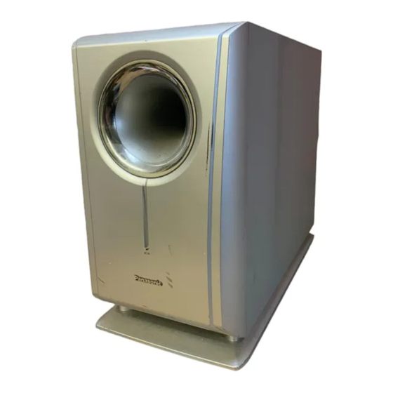
ORDER NO. MD0401014C1 Active Subwoofer System SB-WA720PP Colour (S)...Silver Type SPECIFICATIONS Specification... -
Page 4: Safety Precautions
Music Center: SA-HT720 (PC) System : SC-HT720 (PC) Satellite Speakers: SB-HT720 (P) Active Subwoofer: SB-WA720 (PP) 2004 Panasonic AVC Networks Singapore Pte. Ltd. All rights reserved. Unauthorized copying and distribution is a violation of law. 1. Safety Precautions 1.1. GENERAL GUIDELINES 1. -
Page 5: Leakage Current Cold Check
2. After servicing, see to it that all the protective devices such as insulation barriers, insulation papers shields are properly installed. 3. After servicing, make the following leakage current checks to prevent the customer from being exposed to shock hazards. (This “Safety Precaution”... -
Page 6: Handling The Lead-Free Solder
1.1.2. LEAKAGE CURRENT HOT CHECK (See Figure 1.) 1. Plug the AC cord directly into the AC outlet. Do not use an isolation transformer for this check. 2. Connect a 1.5k , 10 watts resistor, in parallel with a 0.15 capacitors, between each exposed metallic part on the set and a good earth ground such as a water pipe, as shown in Figure 1. -
Page 7: Protection Circuitry
Disconnect AC power, discharge Power Supply Capacitors C546, C547, C548, C549 through a , 1 W resistor to ground. DO NOT SHORT-CIRCUIT DIRECTLY (with a screwdriver blade, for instance), as this may destroy solid state devices. After repairs are completed, restore power gradually using a variac, to avoid overcurrent. Current consumption at AC 120V, 60Hz in NO SIGNAL mode should be ~500 mA . -
Page 8: Disassembly Procedure
Notes : - To prevent damage to circuitry, never short-circuit positive (+) and negative (-) speaker wires. - Be sure to connect only positive (Copper) wires to positive (+) terminals and negative (Silver) wires to negative (-) terminals. 6. Disassembly Procedure “ATTENTION SERVICER”... -
Page 9: Disassembly Flow Chart
Contents - Disassembly of the Speaker Unit - Main Component Replacement Procedures 6.1. Disassembly flow chart The following chart is the procedure for disassembling the casing and inside parts for internal inspection when carrying out the servicing. To assemble the unit, reverse the steps shown in the chart below. 6.2. - Page 10 Step 3: Remove all the screws from the bottom of the speaker unit. Step 4: Remove the screws from the rear panel’s speaker unit guide. Step 5: Remove the screws from the subwoofer.
- Page 11 Step 6: Remove 2 screws from the Power Amp unit. Step 7: Pull out the Power Amp unit slightly as shown. Step 8: Release the connector CN506 then pull out the entire Power Amp unit.
- Page 12 Steps 9 & 10: Remove all the screws. Step 11: Release the connector CN507 to remove the rear panel. - Checking for the Power and AC Inlet P.C.B. Step 12: Remove the screws from the AC Inlet P.C.B.
- Page 13 Steps 13 & 14: Remove the screws. Step 15: Place the Power P.C.B. and the AC Inlet P.C.B. as shown for checking. - Checking for the Transformer P.C.B. Step 16: Remove the screws.
- Page 14 Step 17: Place the P.C.B. as shown for checking. 6.3. Main Component Replacement Procedures 6.3.1. Replacement of the Power IC and Transistor Step 1: Desolder the Power IC and Transistor terminals. Step 2: Remove the screws from the IC501.
-
Page 15: Connection Of The Speaker Wiring
Step 3: Remove the screw. Step 4: Replacement of the Power IC and Transistor. 7. Connection of the Speaker Wiring 8. Block Diagram 9. Schematic Diagram (All schematic diagrams may be modified at any time with the development of the new technology) Note: - The voltage value and waveforms are the reference voltage of this... - Page 16 Components identified by mark have special characteristics important for safety. Furthermore, special parts which have purposes of fire-retardant (resistors), high-quality sound (capacitors), low-noise (resistors), etc. are used. When replacing any of components, be sure to use only manufacturer's specified parts shown in the parts list. Caution ! IC, LSI and VLSI are sensitive to static electricity.
- Page 17 Furthermore, special parts which have purposes of fire-retardent (resistors), high-quality sound (capacitors), low noise (resistors), etc are used. When replacing any of these components, be sure to use only manufacturer’s specified parts shown in the parts list. - The parenthesized indications in the Remarks columns specify the areas or colour.
- Page 18 13.1.2. Cabinet Parts List...
-
Page 19: Electrical Parts List
Ref. No. Part No. Part Name & Description Remarks CABINET AND CHASSIS RFKHBWA720PP SUBWOOFER ASS’Y RMVX0077-J SPEAKER UNIT GUARD RMQX0088-J EVA PACKING RGKX0255-SJ STAND ORNAMENT RGRX0033A-HJ REAR PANEL REM0072-3 SHE187-6J PCB SUPPORT RMN0203 PCB HOLDER RMRX0047-J LED HOLDER RKAX0018-KJ LEG CUSHION RMC0158-S TR-FIXTURE XTW3+15T... - Page 20 Ref. No. Part No. Part Name & Description Remarks Q553 2SD0592ARA TRANSISTOR Q554 KTA1267GRTA TRANSISTOR Q555 2SD0592ARA TRANSISTOR Q556 KTA1267GRTA TRANSISTOR Q557 2SD0592ARA TRANSISTOR DIODES D500 B0AACK000004 DIODE D501 B0JAPG000019 DIODE D502 B0JAPG000019 DIODE D503 MA2C700A0F DIODE D504 B0AACK000004 DIODE D508 B0AACK000004 DIODE...
- Page 21 Ref. No. Part No. Part Name & Description Remarks COMPONENT COMBINATION Z501 ERZV10V511CS ZENER SPEAKER L0AA17A00003 WOOFER RELAY RLY501 RSY0040M-0 PRIMARY RELAY FUSES K5D502AQ0004 FUSE FUSE HOLDERS FC501 EYF52BC FUSE HOLDER FC502 EYF52BC FUSE HOLDER FUSE PROTECTOR K5G502AA0002 5A FUSE PROTECTOR HOLDERS H500 K1YF15000004...
- Page 22 Ref. No. Part No. Part Name & Description Remarks R500 ERC12UGK335D 3.3M 1/2W R501 ERDS2TJ472T 4.7K 1/4W R502 ERDS2TJ472T 4.7K 1/4W R503 ERDS2TJ153T 15K 1/4W R504 ERDS2TJ153T 15K 1/4W R505 ERDS2TJ153T 15K 1/4W R506 ERDS2TJ153T 15K 1/4W R507 ERDS2TJ392T 3.9K 1/4W R508 ERDS2TJ392T 3.9K 1/4W...
- Page 23 Ref. No. Part No. Part Name & Description Remarks R562 ERDS2TJ472T 4.7K 1/4W R563 ERDS2TJ332T 3.3K 1/4W R564 ERDS2TJ224T 220K 1/4W R565 ERDS1FVJ392T 3.9K 1/2W R566 ERG2SJ220E 22 2W R567 ERDS1FVJ152T 1.5K 1/2W R568 ERDS2TJ151T 150 1/4W R569 ERDS1FVJ392T 3.9K 1/2W R570 ERDS2TJ103T 10K 1/4W...
- Page 24 Ref. No. Part No. Part Name & Description Remarks C506 ECBT1H102KB5 1000P 50V C507 ECBT1H180JC5 18P 50V C508 ECBT1H180JC5 18P 50V C509 ECBT1H220JC5 22P 50V C510 ECBT1H220JC5 22P 50V C511 ECBT1H220JC5 22P 50V C512 ECBT1H220JC5 22P 50V C513 F1D1H473A012 0.047 50V C514 ECEA0JKA101B 100 6.3V...
-
Page 25: Packing Materials & Accessories Parts List
Ref. No. Part No. Part Name & Description Remarks C575 ECBT1H103KB5 0.01 50V C576 RCE1HKN100BG 10P 50V C577 ECEA1CKA100B 10 16V C578 ECBT1H103KB5 0.01 50V C579 ECBT1H103KB5 0.01 50V C580 ECEA1HKA100B 10 50V C581 ECA1CM102B 1000 16V C647 ECA1HM101B 100 50V 13.3. - Page 26 AC INLET P.C.B (REPX0430A) CAUTION RISK OF ELECTRIC SHOCK AC VOLTAGE LINE. PLEASE DO NOT TOUCH THIS P.C.B FC501 FC502 (BLU) (BRW) F1 125V 5A T502(SUB TRANSFORMER) JK500 Q516 L500 J500 RLY501 C555 J501 R589 Q519 AC IN R578 C557 C581 120V J502...
-
Page 27: Schematic Diagram
SCHEMATIC DIAGRAM-1 : MAIN SIGNAL LINE : -B SIGNAL LINE POWER CIRCUIT : +B SIGNAL LINE IC501 C551 IC501 0.01 RSN311W64B-P POWER HIC E501 K4CZ01000027 R501 R513 4.7K R502 C507 18P 4.7K R514 C508 18P R524 120K D501-D502 R506 B0JAPG000019 R516 R526 C510 22P... - Page 28 SCHEMATIC DIAGRAM-2 : MAIN SIGNAL LINE : -B SIGNAL LINE POWER CIRCUIT : +B SIGNAL LINE R597 C564 R594 1200P Q513,Q514 R592 KTC3199GRTA R403 100K C565 DC DETECT SWITCH Q514 R599 R591 R593 Q513 6.8K 470K R571 C568 R572 C562 IC502 0.01 3.3K...
-
Page 29: Transformer Circuit
SCHEMATIC DIAGRAM-3 : -B SIGNAL LINE : +B SIGNAL LINE C555 R589 35V4.7 Q516 R578 KRC102MTA SYNC SWITCH CN502 R580 PCONT Q517 POWER CIRCUIT R587 D528 KTC2026 2.7K (CP502) ON SYNC B0EAKM000122 VOLTAGE REGULATOR SCHEMATIC SYS6V DIAGRAM-2 C559 HELP 0.01 C556 R588 0.01... - Page 30 CN501 TO MAIN UNIT CN503 7..1 CP502 CENTER SPEAKER JK502 SURROUND RIGHT SPEAKER LED P.C.B. SURROUND CN507 LEFT SPEAKER H505B/ FRONT RIGHT W505 SPEAKER SPEAKER FRONT LEFT JK501 SPEAKER WOOFER H505A/W505 SOLDER SIDE SOLDER SIDE POWER P.C.B.
- Page 31 IC501 RSN311W64B-P POWER HIC POWER CONTROL CIRCUIT POWER CONTROL/PROTECTION CIRCUIT 12(11) (25) (19) D501 D502 Q506 TO MAIN INTERFACE BLOCK SWITCH (JK700) OF SA-HT500GC-S, Q505 (JK300) OF SA-HT700GCS/GC-S SWITCHING SL(R)/SURRL(R) FILTER JK501(JK502) SURROUND SPEAKER CCH/CENTRE FILTER JK502 CENTRE SPEAKER FILTER SUBWOOFER FL(R)/FRONTL(R) FILTER...
- Page 32 C0AABB000055 B1GCCFJJ0015 RSN311W64B-P KTA1267GRTA KTC3199GRTA 2SD0592ARA KRC102MTA KTC2026 MA2C700A0F B0FBAM000009 B0AACK000004 B0BA9R600002 B0BA01900005 KTA1046 Cathode Anode B0BA6R600008 SLI325URCT31 B0EAKM000122 B0JAPG000019 B0EAKM000117 B0BA5R100013 B0BA01200008 Cathode Cathode Anode Cathode Cathode Anode Anode Anode...
- Page 33 POWER P.C.B(REPX0430A) CAUTION RISK OF ELECTRIC SHOCK AC VOLTAGE LINE. PLEASE DO NOT TOUCH THIS P.C.B J570 CN501 J528 J581 R543 R544 CP502 E500 R539 TO MAIN UNIT R540 D508 Q556 Q513 R583 J567 Q558 R542 J504 R566 R541 R605 J533 R582 Q514...
- Page 34 Q557 D562 Q556 Q552 R583 C570 CN503 R566 R605 J505 C580 J586 Q554 Q555 R582 Q501 R607 R606 J513 Q502 R558 D560 D555 D559 Q520 Q553 D557 R564 R581 R402 J587 D558 J544 D599 J588 J543 J553 J578 D598 J554 J555 J569 J556...