Table of Contents
Advertisement
Quick Links
W V
C P 4
-
7 0
(Lens: Option)
please read these instructions carefully and save this manual for future use.
C P 4
7 0
CAUTION
RISK OF ELECTRIC
SHOCK DO NOT OPEN
CAUTION: TO REDUCE THE RISK OF ELECTRIC SHOCK,
DO NOT REMOVE COVER (OR BACK).
NO USER-SERVICEABLE PARTS INSIDE. REFER SER-
VICING TO QUALIFIED SERVICE PERSONNEL.
The lightning flash with arrow-
head symbol, within an equilat-
eral triangle, is interned to alert
the user to the presence of
uninsulated "dangerous volt-
age" within the product's enclo-
sure that may be of sufficient
magnitude to constitute a risk
of electric shock to persons.
The exclamation point within
an equilateral triangle is intend-
ed to alert the user to the pres-
ence of important operating
and maintenance (servicing)
instructions in the literature
accompanying the appliance.
We declare under our sole responsibility that the product
to which this declaration relates is in conformity with the
standards or other normative documents following the
provisions of Directives EEC/73/23 and EEC/89/336.
Vi deklarerar härmed värt fulla ansvar för att den produkt
till vilken denna deklaration hänvisar är i överensstäm-
melse med standarddokument, eller andra normativa
dokument som framstölls i Direktiv 73/23/EEC och 89/
336/EEC.
Ilmoitamme yksinomaisella vastuullamme, että tuote, jota
tämä ilmoitus koskee, noudattaa seuraavia standardeja
tai muita ohjeellisia asiakirjoja, jotka noudattavat direkti-
ivien 73/23/EEC ia 89/336/EEC. säädöksiä.
WARNING:
To reduce the risk of fire or electric shock, do not expose this appliance to rain or moisture.
PREFACE
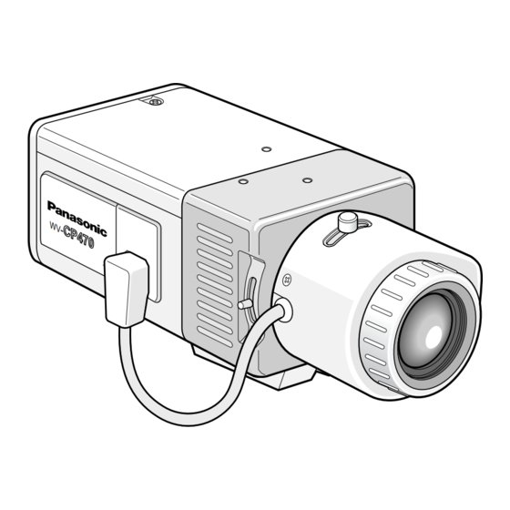
Panasonic's WV-CP470 (WV-CP474E) series colour digital camera introduces a new level of
high picture quality and high resolution through the use of a 1/3-inch interline transfer CCD
image sensor having 753 horizontal pixels (picture elements), and digital signal processing
LSIs. This model offers cutting-edge technology for advanced video surveillance.
PRECAUTIONS
1. Do not attempt to disassemble the camera.
To prevent electric shock, do not remove screws or covers.
There are no user-serviceable parts inside. Ask qualified service personnel for servic-
ing.
2. Handle the camera with care.
Do not abuse the camera. Avoid striking, shaking, etc. The camera could be damaged
by improper handling or storage.
3. The following installation should be made by qualified service personnel or system
installers.
4. Do not use strong or abrasive detergents when cleaning the camera body.
Use a dry cloth to clean the camera when dirty. When the dirt is hard to remove, use a
mild detergent and wipe gently. Then wipe off the remaining detergent with a dry cloth.
5. Clean the CCD faceplate with care.
Do not clean the CCD with strong or abrasive detergents. Use lens tissue or a cotton
tipped applicator and ethanol.
Before attempting to connect or operate this product,
Colour CCTV Cameras
Operating Instructions
Model No.
WV-CP474E
N0102-1042
V8QA5955BN
Vi erklærer oss alene ansvarlige for at produktet som
denne erklæringen gjelder for, er i overensstemmelse
med følgende normer eller andre normgivende doku-
menter som fælger bestemmelsene i direktiven 73/23/
EEC og 89/336/EEC.
Wij verklaren als enige aansprakelijke, dat het product
waarop deze verklaring betrekking heeft, voldoet aan de
volgende normen of andere normatiefve dokumenten,
overeenkomstig de bepalingen van Richtlijnen 73/23/
EEC en 89/336/EEC.
Vi erklærer os eneansvarlige for, at dette produkt, som
denne deklaration omhandler, er i overensstemmelse
med den følgende standarder eller andre normative
dokumenter i følge bestemmelserne i direktivene 73/23/
EEC og 89/336/EEC.
FOR YOUR SAFETY PLEASE READ THE FOLLOWING
TEXT CAREFULLY.
WARNING: This apparatus must be earthed.
The wires in this mains lead are coloured in accordance with
the following code.
Green-and-yellow:
Blue:
Brown:
As the colours of the wire in the mains lead of this appli-
ance may not correspond with the coloured markings identify-
ing the terminals in your plug, proceed as follows.
The wire which is coloured green-and-yellow must be
connected to the terminal in the plug which is marked with the
letter E or by the earth symbol I or coloured green or
green-and-yellow.
The wire which is coloured blue must be connected to
the terminal in the plug which is marked with the letter N or
coloured black.
The wire which is coloured brown must be connected to
the terminal in the plug which is marked with the letter L or
coloured red.
The serial number of this product may be found
on the top of the unit.
You should note the serial number of this unit
in the space provided and retain this instruction
as a permanent record of your purchase to aid
identification in the event of theft.
Model No.
Serial No.
WV-CP470
Printed in Japan
N 19
IMPORTANT
Earth
Neutral
Live
Advertisement
Table of Contents

Related Manuals for Panasonic WV-CP474E


Summary of Contents for Panasonic WV-CP474E
- Page 1 To reduce the risk of fire or electric shock, do not expose this appliance to rain or moisture. PREFACE Panasonic's WV-CP470 (WV-CP474E) series colour digital camera introduces a new level of high picture quality and high resolution through the use of a 1/3-inch interline transfer CCD image sensor having 753 horizontal pixels (picture elements), and digital signal processing LSIs.
-
Page 2: Major Operating Controls And Their Functions
Use the camera at temperatures within –10 °C to +50 °C (14 °F to 122 °F), and humidity below 90 %. The input power source is 220 V to 240 V AC 50 Hz for WV-CP470 and DC 12 V/AC 24 V for WV-CP474E. FEATURES 1. -
Page 3: Video Cable
B. WV-CP474E (12 V DC/24 V AC) The WV-CP474E has an AC/DC compatible input terminal. The 12 V DC or 24 V AC power supply cord can be connected to this terminal. The camera detects the power source auto- matically. -
Page 4: Installation Of Camera
MOUNTING LENS/FOCUS ADJUSTMENT Installation of Auto Iris Lens Connector Install the lens connector (YFE4191J100) when using a video drive ALC lens. (1) Cut the iris control cable at the edge of the lens connector to remove the existing lens connector and then remove the outer cable cover as shown in the figure below. The pin assignment of the lens connector is as follows: Pin 1: Power source;... - Page 5 SETUP 1. CAMERA SETUP MENU This camera utilizes an on-screen user setup menu. • Opening the Setup Menu Press and hold down I for 2 seconds or Highlighted ** CAM SET UP ** more. CAMERA ID ALC/ELC The CAM SET UP menu appears on the SHUTTER ON(DNR-H) monitor as shown in the figure.
-
Page 6: Setting Procedures
SETTING PROCEDURES 1. Camera Identification (CAMERA ID) Setting You can use the camera identification (CAMERA ID) to assign a name to the camera. The camera ID consists of up to 16 alphanumeric characters. The camera ID display can be switched on or off on the monitor screen. To edit the CAMERA ID 1. - Page 7 SETTING PROCEDURES 2-2. ALC Mode with SUPER-D2 OFF and ELC Mode Note: If ELC is selected, set MASK SET according to this procedure. 1. Move the cursor to SUPER-D2 and select OFF. (When you select ELC, ** ALC CONT ** SUPER-D2 is not available.) The MASK BACK LIGHT COMP SET appears on the menu.
- Page 8 6. Synchronization Setting (SYNC) You can select internal sync (INT) mode or line-lock (LL) mode. Additionally, this model accepts the VBS signal (composite colour video or blackburst signal) and VS signal (B/W composite video or composite sync signal). The VD2 signal (multiplexed vertical drive sig- nal) with the composite video output signal from external equipment such as a matrix switcher is also acceptable.
-
Page 9: White Balance Setting (White Bal)
5. Supply the video output signal of the camera to be adjusted and the refer- ** SYNC ** ence gen-lock input signal to a dual- H PHASE ..I trace oscilloscope. 6. Set the oscilloscope to the horizontal rate and expand the horizontal sync portion on the oscilloscope. - Page 10 8. Repeat the procedures above to obtain a satisfactory setting. Notes: • When the camera is not used in a Panasonic Intelligent CCTV System, select OFF. Otherwise, video equipment may malfunction because of the alarm signal misinterpreta- tion for a time code signal.
- Page 11 10-5 BW This function lets you automatically switch from colour to black-and-white pictures in low light conditions such as at night. 1. Move the cursor to BW. 2. Select AUTO1, AUTO2, EXT, ON or OFF using L or M. AUTO1: The camera selects black and white mode if the picture is dark, or colour mode if the picture is bright enough.
-
Page 12: Specifications
Power Source and WV-CP470: 220 V to 240 V AC 50 Hz, 5.1 W Power Consumption: WV-CP474E: 24 V AC 50 Hz, 4.5 W 12 V DC, 480 mA Dimensions (without lens): 70 mm (W) x 55 mm (H) x 118 mm (D) 2-5/8”...