
Related Manuals for Panasonic AG-AC30/PJ


Summary of Contents for Panasonic AG-AC30/PJ
- Page 1 ORDER NO. BSD1608A24CE Memory Card Camera-Recorder AG-AC30/PJ/PB/EJ Model No. © Panasonic Corporation 2016 Unauthorized copy- ing and distribution is a violation of law.
-
Page 2: Table Of Contents
TABLE OF CONTENTS PAGE 1 Safety Precautions -----------------------------------------------2 2 Informtion for your Safety----------------------------------------3 3 How to Replace the Lithium Battery---------------------------9 4 Specifications ---------------------------------------------------- 10 5 Location of Controls and Components ------------------ 12 6 Service Mode ----------------------------------------------------- 15 6.1. Model/Destination Settings ---------------------------- 16 6.2. -
Page 3: Safety Precautions
SAFETY PRECAUTIONS GENERAL GUIDELINES ELECTROSTATICALLY SENSITIVE (ES) DEVICES 1. When servicing, observe the original lead dress. If a Some semiconductor (solid state) devices can be damaged short circuit is found, replace all parts, which have been easily by static electricity. Such components commonly are over-heated or damaged by the short circuit. - Page 4 Model No. AG-AC30PJ/PB...
- Page 8 Model No. AG-AC30EJ...
-
Page 10: How To Replace The Lithium Battery
How to Replace the Lithium Battery Replacement Procedure 1. Remove the SIDE R OPERATION P.C.B.. (Refer to Disassembly Procedures.) 2. Remove the Lithium battery (Ref. No. “B6901” at foil side of SIDE R OPERATION P.C.B.) and then replace it into new one. NOTE: This Lithium battery is a critical component. -
Page 11: Specifications
4 Specifications The following specification is for AG-AC30PJ/PB. Some specifications may differ depending on model suffix. - Page 13 The following specification is for AG-A30EJ. Some specifications may differ depending on model suffix. The page number in this chapter does not show the page number of this service manual.
-
Page 15: Location Of Controls And Components
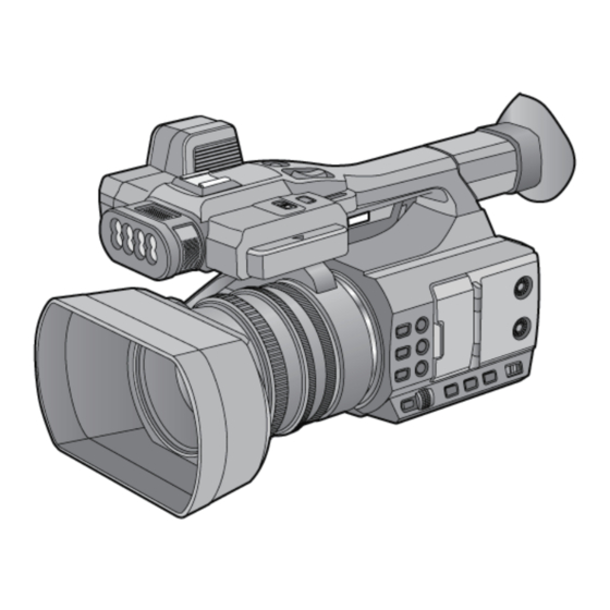
5 Location of Controls and Components The following description is for AG-AC30. Some descriptions may differ depending on model suffix. The page number in this chapter does not show the page number of this service manual. -
Page 18: Service Mode
6 Service Mode Indication method of the service menu 1. Set the Power switch to ON, and turn to ON. 2. While pressing the “MENU”button to “FOCUS ASSIST”button and “Zoom lever” (or “Sub zoom lever”) to W side for more than 3 seconds until the top screen of the Service Mode Menu being displayed. -
Page 19: Model/Destination Settings
6.1. Model/Destination Settings Touch the [ 2 ] of LCD, select model/destination settings. Operation specifications [01] PV100GC [02] PV100GK [03] PV100GW [04] AC30EJ [05] AC30PJ [06] AC30PB Function description • Change the Model/Destination Display the lists of model/distination which the unit can be changed, if a shipment setup is finished. Therefore in some cases, the model/destination that is currently set is only displayed. -
Page 20: Lock Search And Error History Indication
6.2. Lock Search and Error History Indication Touch the [ 4 ] of LCD, select lock search and error history indication. Operation specifications Indication contents • Lock search history indication of camera Display the camera system error code for three histories saved in EEPROM. •... -
Page 21: Power On Self Check Result Display
6.3. Power ON Self Check Result Display Touch the [ 5 ] of LCD, select Power ON self check result display. Operation specifications Indication contents • Power ON self check result display Function to diagnose correct function of the device and interface between devices result display. Display the following communication test result. -
Page 22: Adjustment Function For The Service
6.4. Adjustment function for the Service Touch the [14] of LCD, select the adjustment function for the service. Operation Specifications (until before the start of the adjustment) Function description The service adjustment do setup and adjustment of the following items required in the field service. For a detailed content, such as the adjustment procedure, refer to “9 Measurements and Adjustments”. -
Page 23: Restore The Backed Up Adjustment Data
6.5. Restore the backed up adjustment data Touch the [15] of LCD, select restoring the backed up adjustment data from SD card to the unit. Operation Specifications Function description Restore the adjustment data to new or repaired Main P.C.B. from SD card that the data backed up from original Main P.C.B. before repairs or replacement. -
Page 24: Touch Panel Calibration
6.6. Touch Panel Calibration Touch the [16] of LCD, select the calibration of touch panel. Operation Specifications Function description Calibrate the touch positions of the touch panel. End method of operation • Set the power switch to OFF to turn the unit off. - Page 25 6-7. Hour Meter Reset On the screen in the service mode “10”, Hour Meter or Error information that is displayed in the service mode “4” can be reset. ERROR&HOUR : All Hour Meter and Error Information reset ERROR INFO : All Error Information clear HOUR METER : All Hour Meter reset : Total power-on time reset...
- Page 26 Touch [SET] of LCD. HOUR METER RESET ADJUST DATA RESTORE [ ZOOM.M: 106999 ] Is being Reset : SET Please Wait.. CANCEL : BAK < > > < Reset completed HOUR METER RESET SELECT MENU > [16] ZOOM. M [17] ZOOM.
-
Page 27: Maintencance Parts
7. Maintenance 7-1. Maintenance Parts 7-1-1. Maintenance Schedule Part Name Part No. Replacement Lens Unit* SXW0300 Every 100,000 number of times (ZOOM) (3 Zoom Motors and 3 For the he removal procedure, Zoom Lens Gears) refer to the disassembly procedure. Zoom Lever Unit SYQ0797 Every 100,000 number of times (ZOOM.M) - Page 28 Touch “4” on the service mode menu screen. YES/NO selection screen is displayed, then touch “YES” to display the INFORMATION screen. Touch the [4] of LCD. FF003014 001300 12 17C4 DCBA FF003014 001300 12 17C4 DCBA EXIT AC30EJ(2.0) 50Hz SD(W) EXIT AC30EJ(2.0) 50Hz SD(W) Top Screen of the service mode menu.
- Page 29 03 . INFORMATION ZOOM : Total number of ZOOM Motor operation [ HourMeter ] ZOOM. M : The total number of times of Grip Zoom lever ZOOM : 000808 operation ZOOM. M : 000872 ZOOM. S : The total number of times of Sub Zoom lever ZOOM.
- Page 30 Touch the [>] of LCD. 06 . INFORMATION [ AM Info ] ErrorCount : Total Error count ErrorCount WarningCount : Total Warning count WarningCount : 40 HighFlyWrite : Not used HighFlyWrite Play(SD) Err : Play SD Card error count Play(SD) Err Play(ESD) Err : Not used Play(ESD) Err...
-
Page 31: Firmware Update
Do not power down or pull card while upgrading. or part writing condition and the restart is not made. However software can not be updated, please contact Panasonic Service Engineering. < External Power > The update can not be executed while the camera is operating on battery power. Please use the AC adapter. - Page 32 < Update procedure > 1. Turn the power on. Set the MODE SW to RECORDING side. 2. Insert the SD memory card into the SD memory card slot 1. 3. Press the MENU button to display the setting menu. SD MEMORY CARD SLOT 1 SD Memory card ( Contact side ) 4.
- Page 33 NOTE: When the version is the same or when the version of the update file on the SD card is lower, the message “No need to update.” is displayed. MAINTENANCE MAINTENANCE VERSION VERSION UPDATE UPDATE No need to update. HOUR METER HOUR METER RETURN EXIT...
- Page 34 8. The LCD screen darkens when shifting to the update processing, and the Status indicator goes OFF. During updating software, Status indicator is OFF. The message does not display on the screen. During updating software, In updating succeed, Status indicator is OFF. Status indicator lights.
- Page 35 < How to recover from irregular situations while updating > Solutions are introduced against both Card Plug-Out and Power Interruption troubles to execute the update again. Process Card Plug-Out Power Interruption Data Readout from SD Card Error Message (CHECK CARD) The camera recorder starts up normally.
-
Page 36: Disassembly And Assembly Instructions
8 Disassembly and Assembly Instructions 8.1. Disassembly Flow Chart for the Unit This is a disassembling chart. When assembling, perform this chart conversely. -
Page 37: Pcb Location
8.2. PCB Location... -
Page 38: Disassembly Procedure For The Unit
8.3. Disassembly Procedure for the Item Fig. Removal LED Light P.C.B. (Fig. D13) Screw (V) × 1 Unit Locking tab × 2 LED Light Cover Screw (W) × 2 Item Fig. Removal Mic Case A Lens Hood Unit, (Fig. D1) Lens Hood Unit Flex Lens Mask... - Page 39 Item Fig. Removal Item Fig. Removal 17 Side R Operation (Fig. D26) Screw (q) × 3 28 EVF Unit (Fig. D42) Locking tab × 2 P.C.B. Screw (r) × 9 Handle Case R FP6902 (Flex) Locking tab × 4 Locking tab × 1 EVF Wire Guide Kurupon Ass’y (Fig.
- Page 40 8.3.1. Removal of the Lens Hood Unit, Lens Mask (Fig. D2) 8.3.2. Removal of the Grip Ass’y (Fig. D1) (Fig. D3)
- Page 41 (Fig. D4) 8.3.3. Removal of the Zoom Lever Unit, Power SS Unit, Grip Unit (Fig. D5) (Fig. D6)
- Page 42 8.3.4. Removal of the Side Case L Unit (Fig. D8) (Fig. D7)
- Page 43 8.3.5. Removal of the XLR Rear P.C.B. Unit, AV Jack P.C.B., DC/Remote Jack P.C.B. (Fig. D10) (Fig. D9)
- Page 44 8.3.6. Removal of the Sub Radiation Plate Unit (Fig. D11) (Fig. D12)
- Page 45 8.3.7. Removal of the LED Light P.C.B. 8.3.8. Removal of the XLR Front Unit (Fig. D14) (Fig. D13)
- Page 46 8.3.9. Removal of the Handle Case T Unit, HA Top Angle Unit (Fig. D16) 8.3.10. Removal of the Handle Operation P.C.B. (Fig. D17) (Fig. D15)
- Page 47 8.3.12. Removal of the Handle Slide Unit, LCD unit, LCD Case T, LCD Hinge Unit (Fig. D18) 8.3.11. Removal of the Handle Slide Ass’y (Fig. D19) (Fig. D20)
- Page 48 8.3.13. Removal of the Microphone (Fig. D21) (Fig. D22)
- Page 49 8.3.14. Removal of the Handle Case L Unit 8.3.15. Removal of the ND Case (Fig. D24) (Fig. D23)
- Page 50 8.3.16. Removal of the Side Case R Ass’y 8.3.17. Removal of the Side R Operation P.C.B. (Fig. D25) (Fig. D26)
- Page 51 8.3.18. Removal of the Dial P.C.B., Kuru- 8.3.19. Removal of the MF Unit pon Unit (Fig. D28) (Fig. D27)
- Page 52 8.3.20. Removal of the Lens Relay P.C.B. (Fig. D29) 8.3.21. Removal of the Ring LED P.C.B., Ring LED Unit (Fig. D30) (Fig. D31)
- Page 53 8.3.22. Removal of the Main P.C.B. (Fig. D33) 8.3.23. Removal of the Handle Unit (Fig. D34) (Fig. D32)
- Page 54 (Fig. D37) (Fig. D35) 8.3.25. Removal of the Main Radiation 8.3.24. Removal of the Camera Lens Unit Plate, SD Holder P.C.B. (Fig. D36) (Fig. D38)
- Page 55 8.3.26. Removal of the Battery Catcher P.C.B. (Fig. D39) (Fig. D40)
- Page 56 8.3.27. Removal of the Speaker 8.3.28. Removal of the EVF Unit (Fig. D42) (Fig. D41)
- Page 57 (Fig. D43)
-
Page 58: Measurements And Adjustments
9 Measurements and Adjustments 9.1. Electric Adjustment • An exclusive jig are necessary for electric adjustment. • Connection and location method of the main unit and an exclusive adjustment jig as follows. Figure of connection Figure of image when adjustment... - Page 59 Part Number of jig 1. Basic Jig Item Contents AC adaptor Bandled with camcorder AC Cable Bandled with camcorder 2. Optical Jig for Camera Adjustment Item Part number Remarks Light box VFK1164TDVLB/RFKZ0523* Need external power supply: 12V ± 0.1V /1.8A or over Collimator with focus chart VFK1164TCM02/VFK1164TCM03 Same as DSC...
- Page 60 [Level Shot Adjutment Chart]...
- Page 61 9.1.1. About Light Box When using VFK1164TDVLB Light Box If using VFK1164TDVLB Light Box, remove the lens connection ring by loosing thumbscrew and three hexagon screws. * RFKZ0523 Light Box has no lens connection ring. How to remove the Front Hood In order to utilize maximum of the diffusing surface of light box, some adjustment items need the distance between diffusing surface of light box and camera body becomes several cent-meters.
- Page 62 9.1.2. Adjustment Items Adjustment item as follows.
- Page 63 9.1.3. Adjustment Procedure All adjustments except “Touch Panel Calibration” and “Factory Setting” performs using “14 Adjustment function for the service” in service mode menu. “Touch Panel Calibration” is performed using 16 of service mode menu and “Factory Setting” is performed using 1 of service mode menu.
- Page 64 [Adjustment Procedure] Adjustments and settings are performed following order: 1. Model setting 2. Filename setting for backup to SD card 3. Backing up adjustment data to SD card 4. Checking switches 5. Zoom Lever adjustment 6. Camera adjustment (Iris, Gyro, OIS, Missing pixels) 7.
-
Page 73: Factory Setting
10 Factory Setting 10.1. How To Turn On The Factory Settings? 1. Set the power switch to ON, and turn to ON. 2. While pressing the “MENU”button to “FOCUS ASSIST”button and “Zoom lever” (or “Sub zoom lever”) to W side for more than 3 seconds until the top screen of the Service Mode Menu being displayed. -
Page 74: What Is The Factory Settings
10.2. What Is The Factory Settings? The factory settings clean up and/or refresh the following settings. 1. Setting Values of menu. 2. Clear the time and date setting. 3. Initialize the Zoom position. (set to wide-angle end) The shipment setting position of switches and lever: (After the factory settings, set the switches and lever as following table.) Name Setting position... -
Page 75: Block Diagram
11 Block Diagram 11.1. Overall Block Diagram : VIDEO SIGNAL NOTE LENS(F1.8-3.6 20x) IC3404 : AUDIO SIGNAL NAND FLASH ROM/ ZOOM/ MOS IMAGE 1Gbit : CLK or CONTROL LINE FOCUS IRIS SENSOR MOTOR/ IC3408 GATE IC LCD UNIT X3402 (72MHz) IC601 SUB LVDS:TX IC701,706,763... -
Page 76: Camera Circuit Block Diagram
11.2. Camera Circuit Block Diagram IC3401 CAMERA LENS UNIT (VENUS ENGINE) RL3401 LVDS CK P SENS LVDSCAP K26 LVDS RXCBM RL3402 LVDS CK M SENS LVDSCAM LVDS RXCBP LVDS A P SENS LVDS0P LVDS RX4M LVDS A M SENS LVDS0M LVDS RX4P RL3403 LVDS B P... -
Page 77: System Control Circuit Block Diagram
11.3. System Control Circuit Block Diagram IC3401 KURUPON UNIT LCD UNIT (VENUS ENGINE) FP905 CMD DIAL FP6937 AD TPY RIGHT X RIGHT AD0 IN8 CMD DIAL F0 GPIO161 CMD DIAL F0 AD TPX BOT Y BOT AD0 IN9 KURUPON TOUCH PANEL KURUPON AD TPY LEFT X LEFT... -
Page 78: Video/Audio Signal Process(1) Circuit Block Diagram
11.4. Video/Audio Signal Process(1) Circuit Block Diagram Please check the Fuse Resistor when an output voltage does not output. FUSE RESISTOR: PW DDR1.2V PW DDR1.2V (R6003) PW HIB3.3V QR3414 QR3416 QR3415 IC3414 (RESET) DDR POW ON H (To IC1431/1441/1452-3) PW HIB3.3V IC3404 (NAND FLASH ROM/1G-bit) PW HDM5V... -
Page 79: Video/Audio Signal Process(2) Circuit Block Diagram
11.5. Video/Audio Signal Process(2) Circuit Block Diagram IC3401 (VENUS ENGINE) FL6005 LCD LVDS0P D0 P LVDS TX0P Y3 D0 N LCD LVDS0N LVDS TX0M Y4 FL6006 LCD LVDSCLKP CLK P LVDS TXCP CLK N LCD LVDSCLKN LVDS TXCM FL6007 LCD LVDS1P D1 P LVDS TX1P AA1 LCD UNIT... -
Page 80: Video/Audio Signal Process(3) Circuit Block Diagram
11.6. Video/Audio Signal Process(3) Circuit Block Diagram IC3701 (AVIO) IC3401 PMAD0 PMHP HP DET L IC3702 (VENUS ENGINE) MICIN0L (To IC3401-F18) (SINGLE CLOCK GENERATOR) SVDD CHARGE PUMP JK4001 (HEADPHONES) CH3408 RL3701 PMAD0 or PMAD1 MICIN0R PMAD1 CLK27 M CLKIN CLKOUT INPUT OUTPUT GAIN... -
Page 81: Lens Drive Circuit Block Diagram
11.7. Lens Drive Circuit Block Diagram IC3401 FP6402 (VENUS ENGINE) 2G ZLEDCONT 2G ZABS 2GZABS LEN GPIO155 3G ZLEDCONT 3G ZABS 3GZABS LEN GPIO156 4G ZLEDCONT LEDCONT LEN GPIO129 4G ZABS 4GZABS LEN 2GZOOM 3GZOOM 4GZOOM GPIO157 TOUT LENS TEMP AD2 IN1 CL3401 CH733... -
Page 82: Power Supply(1) Circuit Block Diagram
11.8. Power Supply(1) Circuit Block Diagram Please check the Fuse Rsistor when an output CH1001 voltage does not output. Q1521 FUSE RESISTOR: PW +B (R1001/R1601/R1704/R1801/R1901/R2300) CH1311 CH1002 IC PROTECTOR: PW 5V CH1413 (IP6301/IP6851) QR1521 Q1501 PW HDM5V FL6851 CH1411 JK6853 Q1523 IP6851 PW MIC5V... -
Page 83: Power Supply(2) Circuit Block Diagram
11.9. Power Supply(2) Circuit Block Diagram Please check the Fuse Resistor when an output voltage does not output. CH1414 PW REMO5V FUSE RESISTOR: CH1412 (R1293) PW 5V PW VBUS PW +B PW GYRO3V R PW 5V Q1413 PW MRGYRO3V IC1414 STBY NOISE BOOT... -
Page 84: Wiring Connection Diagram
12 Wiring Connection Diagram 12.1. Interconnection Diagram FP6402 MF UNIT FOCUS RING AV JACK P.C.B. FP6401 FMR GND FMR GND (COMPONENT SIDE) 3G ZBN ZOOM RING 3G ZAP DC BATT WIRE 3G ZBP 3G ZAN : (FOIL SIDE) 3G ZLED CONT 3G ZABS DC/REMOTE JACK P.C.B. - Page 87 Audio ADC (Main P.C.B.) L 4601 G1C100K A 0115 PW_R E G3V PW_R E G1R 8V A UD_GND C4651 D_GND CH4602 6.3V C4611 100P C4603 S_A UDA DC_CS G_CH1_MUX OUT S_A V IO_SCK 6.3V S_A V IO_DT C4652 C4612 CH4601 CH4603 CH4604 C4601...
- Page 88 PW_A UD10R 5V PW_A UD9V PW_A UD9V PW_A UD9V PW_A UD9V PW_A UD9V PW_A UD4R 5V _1 Audio MUX (Main P.C.B.) C0DB GY Y 02835 R 4525 R 4529 R 4533 100K 100K 100K A UD_GND A UD_GND A UD_GND A UD_GND X L R 1_MIC_N CH1_INT L _N...
- Page 89 PW_SPK 3R 2V L 3702 G1C4R 7MA 0073 PW_R E G3V PW_R E G1R 8V CH3701 CH3702 CH3703 S_A V IO_CS S_A V IO_SCK A UD_GND2 S_A V IO_DT R 3701 E _A V IO_R ST D_GND 42 41 R L 3706 R L 3707 R L 3705 R L 3704 R L 3703...
- Page 90 Q1521 R 1522 B 1CHR D000092 T O POWE R FR OM SD_HOL DE R E R J6B WFR 033V PW_A DP_+ PW_+B D1521 B 0JCPE 000038 Q1501 R 1521 R 1571 $[15] POWE R _CT L 1 B 1CHQD000012 100K QR 1541 R 1541...
- Page 91 T O POWE R R 607 PW_L CD1R 8V T X Fig5 IC601 R X 601 $[D1H8R 0040016] C1CB 00002847 T O V IDE O B US20_E V FY 0 B US20_E V FY 1 B US20_E V FY 2 B US20_E V FY 3 B US20_E V FY 4 T O E V F...
- Page 92 LED Light Drive (Main P.C.B.) C3004 C3005 F1J1H225A 928 F1J1H225A 928 50V 2R 2[22] 50V 2R 2[22] 16V 10uF[22] F1J1C1060001 R 3008 T O HA NDL E _OP T O POWE R C3003 (PW=1mm) (PW=1mm) PW_L E D_NOR E G L E D_L IGHT _A G1C100MA 0461 (PW=1mm)
- Page 93 Lens Drive (Main P.C.B.) R OL L GY R O C753 R 761 G_GY R OR IC761 C0A B GA 000035 V CC L PF V DD IC751 V SS E WT S9R CL 11 C766 V R E F A R 765 R 766 27K [D]...
- Page 94 [HDMI JA CK ] JK 6001 A UDIO_MUX K 1FY 119E 0025 T O SD_HOL DE R T O HA NDL E T O V IDE O G_INT MICL _P X L R 1_MIC_N R 6002 HPDT CT G_INT MICL _N CH1_INT L _N Main connection (Main P.C.B.) L B 6005...
- Page 95 MOS connection (Main P.C.B.) T O V IDE O SE NS_L V DSCA P SE NS_L V DSCA M SE NS_L V DS0P SE NS_L V DS0M SE NS_L V DS1P SE NS_L V DS1M SE NS_L V DS2P SE NS_L V DS2M T O MOS_PCB SE NS_L V DS3P FP301...
- Page 96 CH1001 Q1901 CH1901 B 1CHR D000092 T O L E D T O CHA R GE _R T C R 1901 D1JB R 084A 023 PW_+B PW_L E D_NOR E G CH1701 B 1CHR D000092 L 1701 D1704 L 1702 Q1701 G1C100MA 0569 B 0E CK M000038...
- Page 97 T O SD_HOL D PW_SD1_3R 2V Q3303 T O POWE R B 1A DGE 000014 PW_SD3R 2V R 3309 C3305 IC3301 0.01u T O V IDE O C0DB GY Y 00779 SD1_P_ON_L T O SD_HOL D/V IDE O R 3313 V IN V OUT PW_SD1_3218V...
- Page 98 T O POWE R R 3435 $[18] PW_DDR 1R 8V PW_DDR 1R 8V 350mA PW_DDR 1R 2V PW_DDR 1R 2V R 3403 $[18] PW_R E G1R 8V PW_R E G1R 8V R 3408 $[18] PW_A NA 1R 8V PW_A NA 1R 8V POWE R (1.8V ) R 3404 POWE R...
- Page 99 Lens Relay (Lens Relay P.C.B.) T O L E NS(Z198K 5) T O MA IN FP6402 FP6401 K 1MY 51B A 0667 K 1MY 51A A 0199 4GZA N_L E N 4GZA N_L E N 4G ZA N 4G ZA N 4GZB P_L E N 4GZB P_L E N 4G ZB P...
- Page 100 XLR Rear 2 (XLR Rear P.C.B. Unit) L 4201 L B 4201 C4207 B 1A DB L 000010 B 1A B B L 000006 J0JCC0000276 G1C100MA 0495 F2JZZ1R 00004 Q4202 Q4203 PW_48V G_X L R 2_2 PW_48V _FL T PW_48V _FL T C4205 F1G2A 471A 001 L B 4202...
- Page 101 IC4403 C0DB GY Y 02835 X L R 2_4R 5V X L R 2_9V X L R 2_9V X L R 2_9V X L R 2_9V C4404 PW_A UD10R 5V R 4410 DA 3J101F0L D4401 R 4437 MIC_GND MIC_GND MIC_GND MIC_GND G_X L R 2_L INE _N [R OHM] B 1GDCFY Y 0087=DT A 044E E B T L...
- Page 102 Ring LED (Ring LED P.C.B.) T O MA IN FP6551 K 1MN06A 00065 D_GND R ING_B _L E D D_GND D_GND R ING_R _L E D D_GND D6552 D6551 B 3A E B 0000139 B 3A A B 0000343 B L UE L E D R E D L E D R L 6551 R L 6552...
- Page 103 SD Holder (SD Holder P.C.B.) PW_SD1_3218V CA R D_SD1L E D R 3910 E _CA R D_SD1PR O R 3911 E _CA R D_SD1DE T R 3912 $[18] R 3908 C3903 Q3901 $[B 1A DK B 000015] C3925 C3905 PP3901 R 3909 R 3913 $[22]...
- Page 104 IC4303 C0DB GY Y 02835 X L R 1_4R 5V X L R 1_9V X L R 1_9V X L R 1_9V X L R 1_9V C4304 T O MIC X L R 1_9V _MIC PW_A UD10R 5V R 4310 DA 3J101F0L D4301 R 4337...
- Page 105 MIC (Handle Operation P.C.B.) MIC4R 5V MIC2R 5V MIC4R 3V B 1A B CF000271 Q4801 X L R 1_9V _MIC PW_MIC5V 4700 R 4827 MIC_GND MIC_GND [R ch R ear] [R ch Front] MIC_GND MIC_GND MIC_GND M IC_GND MIC_GND MIC_GND MIC4R 3V MIC4R 3V MIC2R 5V...
- Page 106 T O MA IN T O MONIT OR PS6719 FP6714 K 1K Y 10A A 0805 K 1MY 30B A 0633 S_CL K _L CD S_CL K _L CD S_CS_L CD S_CS_L CD S_DO_L CD S_DO_L CD E _L CD_R ST D_GND E _L CD_R ST D_GND...
- Page 107 LED Light (LED Light P.C.B.) L E D_L IGHT _2 CL 6502 L E D_L IGHT _1 CL 6501 (NICHIA ) (NICHIA ) D6504 D6508 B 3A FB 0000842 B 3A FB 0000842 (NICHIA ) (NICHIA ) D6503 D6507 B 3A FB 0000842 B 3A FB 0000842 (NICHIA ) (NICHIA )
- Page 108 Dial (Dial P.C.B.) T O CA M_OP T O K UR UPON FP6936 FP6937 K 1MN06A 00065 K 1MY 04B A 0641 DIA L _CMD_F0 CMD_DIA L _F0 D_GND K UR UPON K UR UPON D_GND CMD_DIA L _F1 CMD_DIA L _F1 D_GND E T 6931 $[K 4CZ01000046]...
- Page 109 Side R Operation (Side R Operation P.C.B.) [A UDIO V R 1] [A UDIO V R 2] PW_R E G1R 8V R L 6901 R L 6902 [INPUT 1 SE L E CT ] A UDIO_V R 1 A UDIO_V R 2 PW_R E G3V R X 6905 [INPUT 2 SE L E CT ]...
- Page 110 Battery Catcher (Battery Catcher P.C.B.) MA R K :6 IP6301 B A T T E R Y CA T CHE R P6301 K 5H6321A 0011 JK 6301 K 1K A 02B 00247 K 4ZZ04000049 B A T T _+ B A T T _- D4E DY 1310001 V A 6301 D4E DY 1310001...
- Page 111 DC/Remote Jack (DC/Remote Jack P.C.B.) R 6860 R 6875 1800[D] 18K [D] R 6869 R 6866 [FOCUS/IR IS] T O A V _JA CK C6859 PS6851 B 1HFCFA 00050 R 6857 0.1u K 1K B 20A A 0094 JK 6851 Q6804 K 2HC106B 0010 PW_R E G3V...
- Page 112 AV Jack (AV Jack P.C.B.) R L 4001 T O DC_WIR E D_R E MO PP4001 R L 4002 K 1K Y 20A A 0347 PW_R E G3V PW_R E G3V [HE A DPHONE ] PW_R E G3V D_GND HPCOM D_GND D_GND L B 4006...
- Page 137 Exploded Views B160 B159 B124 B158 B125 B123 B162 B163 B164 B155 B154 B157 B127 B156 B169 B166 B168 B167 B165 B172 B170 B171 B151 B196 SPL-1...
- Page 138 B106 B105 B102 B101 B104 B103 B108 B107 53-1 B114 B113 B111 B112 B116 B115 SPL-2...
- Page 139 65-1 65-2 B176 B177 SPL-3...
- Page 140 B183 B184 B181 B182 181-1 181-2 B147 B146 B185 B193 B191 B192 B190 B142 B141 B138 B139 B134 B140 B132 B133 B131 B137 B135 B136 B144 B145 131-1 SPL-4...
- Page 141 Components identified with the mark have the special characteristics for safety. When replacing any of these components, use only the same type. (EJ only) (EJ only) (Japan only) (PB only) (PJ only) 322-1 322-2 323-3 323-2 323-1 SPL-5...
- Page 142 FRAME ASSEMBLY & PACKING PARTS LIST Ref. No. Part No. Part Name & Description Remark SEP0832AA MAIN P.C.B. SEP0816AA LENS RELAY P.C.B. SEP0818AA XLR REAR P.C.B. UNIT SEP0831AA RING LED P.C.B. SEP0817AA SD HOLDER P.C.B. SEP0819AA HANDLE OPERATION P.C.B. SEP0826AA DIAL P.C.B.
- Page 143 FRAME ASSEMBLY & PACKING PARTS LIST Ref. No. Part No. Part Name & Description Remark VMP8492 SHOE ANGLE VGU9988 REC BUTTON SYK1613 SIDE CASE R UNIT 131-1 VKA0397 SET LEG CUSHION K0RE00300042 JOG DIAL UNIT K0RE00300044 VGU0K96 AUDIO VR KNOB VGU0K96 AUDIO VR KNOB VGQ1A44...
- Page 144 FRAME ASSEMBLY & PACKING PARTS LIST Ref. No. Part No. Part Name & Description Remark SPN0540 CUSHION(TOP) VPF1486 PROTECT BAG SPN0541 CUSHION(BOTTOM) SPG0840 PACKING CASE 337-1 SPG0841 PACKING CASE(T) 1 For AJ-AC30PJ/EJ SYA0073 LENS CAP SYA0071 DIFFUSION FILTER SYA0072 COLOR CONVERSION FILTER SCREW LIST Ref.
- Page 145 SCREW LIST Ref. No. Part No. Part Name & Description Remark XQN2+B8FJK SCREW XQN2+B8FJK SCREW XQN2+B8FJK SCREW XQN2+B8FJK SCREW XQN2+B8FJK SCREW XQN2+B8FJK SCREW XQN2+B8FJK SCREW XQN2+B6FJK SCREW XQN2+BJ12FJK SCREW XQN2+BJ6FJK SCREW XQN2+BJ6FJK SCREW XQN2+BJ6FJK SCREW XQN2+BJ6FJK SCREW XQN2+BJ8FJK SCREW XQN2+B8FJK SCREW XQN2+BJ8FJK SCREW...
- Page 146 SCREW LIST Ref. No. Part No. Part Name & Description Remark B122 XQS2+A12FN SCREW B123 XQS2+A12FN SCREW B124 XQS2+A12FN SCREW B125 XQN2+BJ6FJK SCREW B131 XQN2+BJ8FN SCREW B132 XQN2+BJ8FN SCREW B133 XQN2+BJ8FN SCREW B134 XQN2+BJ5FJK SCREW B135 XQN2+BJ5FJK SCREW B136 XQN2+BJ5FJK SCREW B137 XQN2+BJ5FJK...
- Page 147 ELECTRICAL REPLACEMENT PARTS LIST Ref. No. Part No. Part Name & Description Remark SEP0832AA MAIN P.C.B. SEP0816AA LENS RELAY P.C.B. SEP0818AA XLR REAR P.C.B. UNIT SEP0831AA RING LED P.C.B. SEP0817AA SD HOLDER P.C.B. SEP0819AA HANDLE OPERATION P.C.B. SEP0826AA DIAL P.C.B. SEP0825AA SIDE R OPERATION P.C.B.