Advertisement
Quick Links
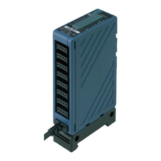
Simple Wire-saving Unit for Leak Detection Sensor
(NPN output type)
EX-FC1
Thank you very much for purchasing Panasonic products.
Please read this Instruction Manual carefully and thoroughly for the correct
and optimum use of this product.
Kindly keep this manual in a convenient place for quick reference.
In case of using sensing devices for prevention of accidents etc. which
damage a human life or properties, be sure to construct the system so
that all of the machinery operates to the safety side. This product itself
does not posses control functions needed for accident prevention or
safety maintenance.
1
OUTLINE
● This is the simple wire-saving unit which can be connected with max. 8
leak detection sensors (NPN output type).
● Even if only one leak detection sensor (NPN output type) is connected to
this product, the output is gained when leak is detected or the sensor is
mounted improperly.
● Since the exclusive snap male connector (SL-CP1) is used for connec-
tion, wire-saving can be easily made.
2
PART DESCRIPTION
2
1
3
4
Designation
Normal indicator
Lights up when sensors are connected to each channel
1
(Green × 8)
and the connection setting switch is set to ON.
Lights up when leak is detected by any sensor con-
Error indicator
nected or any sensor is mounted improperly.
2
(Red × 8)
For details, refer to "
SWITCH."
Output indicator
3
Lights up when the output relay is ON (Normal).
(Orange)
Set the switch to ON when the leak detection sensor is
Connection setting
4
connected, set to OFF when the leak detection sensor
switch
is not connected.
5
Connector
Connect the leak detection sensors (NPN output type).
INSTRUCTION MANUAL
MJE-EXFC1 No.0062-57V
5
Function
CONNECTION SETTING
SEN TRONIC
056 222 38 18
AG
3
MOUNTING
● When mounting the unit, be sure to use the unit mounting base
(MS-SL-2) (accessory).
● When installing the unit mounting base to the unit, insert the base
aligned with the grooves of the unit and move until the unit stopper is
locked.
1. Insert aligned with the
groove of the unit.
Grooves
● Two installation positions are available for the unit mounting base so that
the unit direction can be changed. Install the base at one of them.
Mounting position 1
Unit
Unit mounting base
Din rail stopper
● In case of using a DIN rail or the
mounting bracket (MS-DIN-3)
(optional).
1. Fit the rear part of the unit mount-
ing base on a 35mm width DIN rail
or the mounting bracket (MS-DIN-3)
(optional).
2. Press down the front part of the
unit mounting base on the 35mm
width DIN rail and fit the front part
of the base on the DIN rail.
* For removal, insert a flathead
screwdriver into the DIN rail stop-
per and pull towards yourself.
● In case of using screws
• Mount using M4 pan head screws
with a tightening torque of 0.8N·m
or less. However, in case of side
mounting, make sure to mount the
unit such that the unit stopper faces
front.
I/O CIRCUIT DIAGRAM (for 1 channel)
4
Terminal No.
12 to 24V DC±10%
IN
*1
No
connection
0V
Sensor side
Note: Since the output does not incorporate a short-circuit protection circuit, make sure to use
this product within the specification and take care against wrong wiring.
* 1
NPN transistor open collector or no-voltage contact
mailbox@sentronic.com
www.sentronic.com
2. Make the unit stopper
locked.
Unit stopper
Mounting position 2
Unit
Unit mounting base
DIN rail stopper
DIN rail stopper
2
1
35mm width DIN rail or the mounting
bracket (MS-DIN-3) (Optional)
Flathead screwdriver
DIN rail stopper
Unit
Unit stopper
Unit mounting
base
Color code
(Brown) 12 to 24V DC±10%
(White) OUT
Relay contact
(1a contact)
(Black) OUT
(Blue) 0V
Internal circuit
Users' circuit
or
M4 pan head screw
Please arrange
separately.
Advertisement

Related Manuals for Panasonic EX-FC1


Summary of Contents for Panasonic EX-FC1
- Page 1 2. Make the unit stopper groove of the unit. locked. MJE-EXFC1 No.0062-57V Thank you very much for purchasing Panasonic products. Please read this Instruction Manual carefully and thoroughly for the correct Grooves and optimum use of this product. Kindly keep this manual in a convenient place for quick reference.
- Page 2 8 points connected, insert it into the connector SL-CP1 (Accessory) -10 to +60ºC (No dew condensation or icing allowed) of the EX-FC1 reliably till it stops. Ambient temperature Storage: -20 to +70ºC Ambient humidity 35 to 85% RH, Storage: 35 to 85% RH...