Advertisement
Quick Links
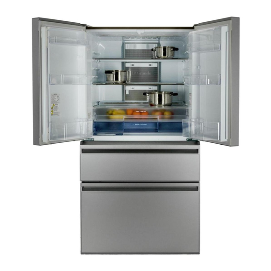
HOME REFRIGERATORS
SERVICE MANUAL
MR-LXR68EM-GSL-R
Models
MR-LXR68EM-GBK-R
R..........Russia
CONTENTS
1. SPECIFICATIONS.......................................................................................................................
2. OUTLINES AND DIMENSIONS..................................................................................................
3. WIRING DIAGRAM.............................................................................................................
4. REFRIGERANT CIRCUIT...........................................................................................................
5. NAME OF PARTS......................................................................................................
6. TROUBLE SHOOTING.....................................................................................
6.1 FUNCTION OF OPERATION PANEL.....................................................................
6.2 FLOW CHART OF SELF-CHECK...............................................................
6.3 BLOCK DIAGRAM OF PRINTED CIRCUIT BOARD..........................................
6.4 AUTO ICE-MAKER..........................................................................................
6.5 FLOW CHART OF TROUBLE CRITERION............................................
6.6 TROUBLE CRITERION OF MAIN PARTS..........................................
6.7 TEST POINT DIAGRAM OF MAIN CONTROL BOARD......................
7. DISASSEMBLY INSTRUCTIONS.............................................................
8. PART LISTS.............................................................................................
Changes for the Better
2018
NO. SM-RE-1822
1
3
4
6
7
9
9
22
25
25
28
35
40
41
46
Advertisement

Related Manuals for Mitsubishi Electric MR-LXR68EM-GSL-R


Summary of Contents for Mitsubishi Electric MR-LXR68EM-GSL-R
- Page 1 Changes for the Better 2018 HOME REFRIGERATORS SERVICE MANUAL NO. SM-RE-1822 MR-LXR68EM-GSL-R Models MR-LXR68EM-GBK-R CONTENTS 1. SPECIFICATIONS........................2. OUTLINES AND DIMENSIONS....................3. WIRING DIAGRAM……………....................4. REFRIGERANT CIRCUIT…………….................... 5. NAME OF PARTS...................... 6. TROUBLE SHOOTING…………………………………………………………………………. 6.1 FUNCTION OF OPERATION PANEL…………………………………………………………… 6.2 FLOW CHART OF SELF-CHECK………………………………………………………...
- Page 3 SPECIFICATIONS 1-1 SPECIFICATIONS MR-LXR68EM-R Power supply 220 V 50Hz Total capacity (AS Gross) 630 (R : 333 V : 117 F : 180) 1798 x 900 x 735 Dimensions (HXWXD) Cabinet Acrylic resin coated steel Food liner ABS resin Cabinet Foamed cyclopenthane Refrigerator door Foamed cyclopenthane...
- Page 4 1-2 ELECTRICAL PARTS SPECIFICATION MR-LXR68EM-R Model EEI91E13DWH Power supply 220 V, 50Hz Rated input 37 (1620 rpm) Compressor Starting current 6 (current limiter) Rated current 0.86 (1620 rpm) 16.72 Winding resistance (A.T. 20 Ω Model MM3-71CCY Motor protector Ambient temperature Sec.
- Page 5 OUTLINES AND DIMENSIONS MR-LXR68EM-R Unit : mm Required Space For Installation...
- Page 6 WIRING DIAGRAM (SKELETON WIRING DIAGRAM) MR-LXR68EM-R...
- Page 7 MR-LXR68EM-R (ACTUAL WIRING DIAGRAM)
- Page 8 REFRIGERANT CIRCUIT MR-LXR68EM-R...
- Page 9 NAMES OF PARTS MR-LXR68EM-R...
- Page 11 TROUBLESHOOTING 6.1) FUNCTION OF OPERATION PANEL (1) Function of normal operation Touching will cause the operable icons to light up. To save power, all displays other than are usually turned off (it turns off if there is no operation for about 30 seconds). Home Icon Child safety lock When turning ON or OFF settings, touch one of these.
- Page 12 (2) Demonstration mode for shop display 1. Setting - Within 1 minute after power supply turns on, touch the simultaneously for 5 seconds with the door of the refrigerator compartment opened. * When the setting is complete, 2 short beeps sound is heard and is displayed.
- Page 13 (5) Fine adjustment of temperature (6) Service Diagnostics Function 1) Out Line - The chart in next page shows the outline of service check function. - “Service diagnostics function entry” needs to be set in order to perform each check mode. - After the service check function entry,”...
- Page 14 Note : After one of the check modes starts, the mode continues operating even if the door gets closed. (Open the door when releasing the check mode.) * Refer to the following sections about the operation procedure and the display of each check mode. - In order to release “service diagnostics function entry,”...
- Page 15 2) Compressor rotational speed change mode 1. Setting • With the freezer compartment door open, touch simultaneously for 3 seconds until 2 short beeps sound. will blinks. • With the freezer compartment door open, touch to select blinking • With the freezer compartment door open, touch for 3 seconds until 2 short beeps sound.
- Page 16 4 Changing the rotational speed After setting this mode, the rotational speed of the compressor changes every time when is touched. The ones place and tens place of the rotational speed(rps) are displayed separately. (Basically the compressor starts operation at level 10, however, it may be different depending on models, or as a result of specification change.) <Change of rotational speed>...
- Page 17 3) Damper Operation Mode 1 Setting • With the freezer compartment door open, touch simultaneously for 3 seconds until 2 short beeps sound. will blinks. • With the freezer compartment door open, touch to select blinking • With the freezer compartment door open, touch for 3 seconds until 2 short beeps sound.
- Page 18 4 Opening and closing dampers 3 : freezer) (2) To open the damper, light up by touching . To close the damper, turn off by touching again. **Damper operation indicators on the left represents the current state and on the right represents the next state of the damper operation. - Both buttons indicate that the damper is open when they are lit, and they indicate that the damper is closed when they are not lit.
- Page 19 4) Thermistor temperature check mode 1 Setting • With the freezer compartment door open, touch simultaneously for 3 seconds until 2 short beeps sound. will blinks. • With the freezer compartment door open, touch to select the blinking • With the freezer compartment door open, touch for 3 seconds until 2 short beeps sound.
- Page 20 c) Ones place of the thermistor temperature - Display of corresponds to the values 8, 4, 2 and 1 respectively. The sum of the values corresponding to the lit indicators is the ones place of thermistor temperature. Display Corresponding values d) Plus and minus sign(±) of the thermistor temperature - Plus and minus sign(±) of the thermistor temperature are represented by Display...
- Page 21 5) Setting adjustment mode The temperature of each compartment and the energization rate of the heaters can be adjusted by touching the buttons on the operation panel. There are two modes. In the “setting adjustment mode”, the setting temperature of the compartment is adjustable.
- Page 22 2. Select the adjustment level of the set temperature by touching Each touch of changes the adjustment level of the set temperature along with a short beep. There are 5 adjustment levels of set temperature, and the selected level is displayed. Temperature adjustment display Adjustment level Change of the set temperature...
- Page 23 Door Alarm System : Door alarm has been installed so that one will not forget to close the door. • The alarm beeps in the following cases: 1. Any of the doors is left open. 2. The freezer fan motor or the box fan motor(At machine room) has a failure. Alarm sound pattern 2.
- Page 24 6.2 ) FLOW CHART OF SELF-CHECK (1) Troubleshooting with self-check This refrigerator has self-check feature to clarify and indicate where & what the trouble is.You can perform operation checks and identify malfunction of electric or electronic parts.Error history is recorded and can be displayed by the refrigerator. Self - check Operate the ice-making test.
- Page 25 (2) Timing in self-check * Trouble of Defrost heater : Self-check is conducted after defrosting. (Make sure to check the display before unplugging the power cord because it is automatically reset once the power cord is unplugged.) * Trouble of Ice maker : Touch for 5 seconds to operate the automatic ice maker.
- Page 26 Display Corrective Display Error code Trouble Detecting method Check point Control measures Tens place Ones place 1. Connector CN9S on control board, Repair the • When the motor damper for refrigerator compartment REFRIGERATOR 2-pin wire to wire connector contact failure. is open, the motor damper for chilled Trouble of There is a short or open circuit in the refrigerator...
- Page 27 6.3) BLOCK DIAGRAM OF PRINTED CIRCUIT BOARD For 340 V DC system For 240 V AC system For 5 V DC system - Compressor - Defrost heater - Freezer compartment thermistor - Water pipe heater - Refrigerator compartment thermistor For 12V DC system - Vegetable compartment heater - Defrost thermistor - Freezer fan motor...
- Page 28 (3) Operation by ice making test Touch The sensor lever The ice tray is The water pump Completion 5 seconds detects the amount turned over and motor operates. When error code still occur, of ice. return. please do inspection check for the ice-maker gear box, The sensor lever once The ice tray turns over...
- Page 29 (5) Troubleshooting for automatic ice maker - There is a possibility of a failure on the ice making gear box, deficiency in cooling performance, or detection of full ice level in the ice storage box. 1. Check inside of the ice storage box. - Ice cubes are not stored flatly ->...
- Page 30 6.5) FLOWCHART OF TROUBLE CRITERION Excessive cooling No cooling, poor cooling Is the temperature of Set the temperature Is the temperature of Set the temperature refrigerator compartment, set refrigerator compartment, set Keep the food away Only food around the air Open the refrigerator Proceed to "...
- Page 31 Excessive cooling No cooling, poor cooling Is it setting to Do setting to set to Do setting to set ? Open the refrigerator Only food around the air Proceed to " [6] The Keep the food away compartment door and press the freezer fan motor outlet gets frozen.
- Page 32 Poor cooling Is the set temperature of freezer compartment, set to Set the temperature to Proceed to " [6] The freezer fan Does cool air blow from air outlet when opening the refrigerator motor does not work " compartment door and press the both two side of door switch ? Check the freezer compartment thermistor.
- Page 33 Inverter-related indication “Compressor does not operate” Error Abnormality Possible cause Symptom Corrective measures code Trouble of • There is any The com- Replace the control board. inverter circuit trouble in the pressor circuit which does not detects phase rotate. current of com- pressor.
- Page 34 Inverter-related indication “Compressor does not operate” Error Abnormality Possible cause Symptom Corrective measures code 1. Locate the trouble and decide on the measures. • Failed wiring • Poor connection The compres- • Decide the measures by checking the followings. continuity of connectors sor cannot be (1) Poor connector connections.
- Page 35 Poor cooling Short-circuit the terminal no. 1 and 2 of the compulsory Check the following and explain the defrosting terminals (CN7M) on the control board to actuate Yes (heats up) result: half-open door, gap between the compulsory defrosting function and check whether the gaskets, the amount of ice.
- Page 36 Excessive cooling / Food frozen (1) Confirm about Thermistor / Vegetable heater / Control P.C. board(Refcon assy) Replace the display Error code operation board.(This After ice making test operation, does the Check the resistance for the A.T. 18 display A.T. thermistor was error code 13(Refrigerator thermistor) / error thermistor which locate at included inside display...
- Page 37 6.6) TROUBLE CRITERION OF MAIN PARTS Components/ Parts Mounted Check Method and Criterion Position Part Name Compressor in EEI91E13DWH Model the machine Rated input 37 (1620 rpm) chamber at the Starting current rear side of 0.86 (1620 rpm) Rated current the frame (For only 1 minute after start up) Normal...
- Page 38 Components/ Check Method and Criterion Parts Mounted Position Part Name In the fan grille of the 12537JE-13P-BU-F2 Model freezer compartment. DC brushless Type Measure the resistance with a tester.(Ambient temperature:Room temperature 15 C ~ 25 Normal Abnormal (faulty) Between 3 - 1 (GND and Between 3-1 : open( ) or Freezer fan Vcc): About 25k...
- Page 39 Components/ Parts Mounted Check Method and Criterion Part Name Position (Defrost thermistor) Measure the resistance with a tester according to the following graph. Evaporator (Thermistor resistance values against temperature) (Chilled thermistor) Resistance measured under the ambient temperature from -50 C to +50 On the lower part of 1.
- Page 40 Components/ Check Method and Criterion Parts Mounted Position Part Name Measure the resistance with a tester. At the left bottom of Black vegetable Normal Abnormal (faulty) compartment Black 500~1500 Water supply Open () pipe heater (20~30ºC) Rated input The heater turns on with the energization rate adjusted according to Operation method each setting for the R &...
- Page 41 Components/ Check Method and Criterion Parts Mounted Position Part Name On the ceiling of the refrigerator compartment(Upper side) and on It lights up while the refrigerator compartment door is open. (If the Interior LED lighting door stays open for 60 minutes in a row, the LED automatically goes the control panel (Lower side) duration out.
- Page 43 DISASSEMBLY INSTRUCTIONS MR-LXR68EM-R Plug out before work. Check the automatic ice-maker by pressing ice making stop switch. In assembling & disassembling parts use several kind of screws and rivets. Do not mistake to use them. Rivet 4 x12 Stainless steel 4 x12 (Black) With metal washer OPERATING PROCEDURE PHOTOS...
- Page 44 OPERATING PROCEDURE PHOTOS Part inside the refrigerator compartment Glass shelf R assy (1) Remove interior parts from the refrigerator compartment : Glass shelf R assy(2pcs), Glass top plate assy, Chilled case door, Slide chilled case (up), Slide chilled case(low) (See photo 5) Chilled Partition C case...
- Page 45 OPERATING PROCEDURE PHOTOS Vegetable case cover (4) Remove 6 screws and you can take vegetable case Screw cover out.(See photo 10-1, 10-2) Water pump motor Water pump motor Water pump motor Photo 10-1 (5) Remove 2 screws Water pipe(upper and cut the lead side) Screw wire for take out...
- Page 46 OPERATING PROCEDURE PHOTOS Drip tray Catch No.1(For Fan grille evaporator) (9) Remove left and right side screw (2 screws per each side.) (See photo 14) Catch No.2(For heater roof) Heater roof,Defrost heater Groove No.3(For (10) Lift up the evaporator from catch no.1.(See photo 15) defrost heater) (11) Peel off the tape that fixes lead wires on the side wall of Photo 15...
- Page 47 OPERATING PROCEDURE ロ ロ ロ ロ ロ ロ ロ ロ ロ Dryer Compressor Drain pan Outer fan motor Charge pipe ロ ロ ロ (Low pressure side) Charge pipe (High pressure side)
- Page 48 PARTS LIST DOOR PARTS MR-LXR68EM-R...
- Page 49 DOOR PARTS Q'TY/UNIT PRICE/PIECE MR-LXR68EM-R PART NO. RoHS PART NAMES SPEC (US$-FCA) KIEBK5704 <G> HINGE ATTACH UP Without magnet gasket RL, rotational heater KIEBK5009 <G> DOOR RL board assembly, display pcb assy set, lead KIEBK6009 <G> wire cover with hinge up KIEBK5180 <G>...
- Page 50 BODY PARTS MR-LXR68EM-R...
- Page 51 BODY PARTS Q'TY/UNIT PRICE/PIECE PART NO. RoHS PART NAMES SPEC (US$-FCA) MR-LXR68EM-R KIEBK5326 <G> ELECT COVER ASSY KIEBK5858 <G> CONTROL PANEL ASSY Include all of electrical part and plastic part. KIEZ87807 <G> CONNECTOR BOX KIEBK5802 <G> DUCT V ASSY KIEBK5818 <G>...
- Page 52 ACCESSORY PARTS MR-LXR68EM-R...
- Page 53 ACCESSORY PARTS Q'TY/UNIT PRICE/PIECE PART NO. RoHS PART NAMES SPEC (US$-FCA) MR-LXR68EM-R KIEBK5429 <G> GLASS SHELF R ASSY KIEBK5479 <G> GLASS TOP PLATE ASSY KIEBK5413 <G> SLIDE CHILLED CASE (UP) KIEBK6413 <G> SLIDE CHILLED CASE (LOW) KIEBK5418 <G> CHILLED CASE DOOR KIEBK4409 <G>...
- Page 54 ELECTRICAL AND UNIT PARTS MR-LXR68EM-R...
- Page 55 ELECTRICAL & UNIT PARTS Q'TY/UNIT PRICE/PIECE PART NO. RoHS PART NAMES SPEC MR-LXR68EM-R (US$-FCA) 1 KIEBQ5339 <G> REFCON ASSY 2 KIEBK5363 <G> LED COVER TOP ASSY 3 KIEHJ3313 <G> THERMISTOR (R) 4 KIEBL3354 <G> PLUG CORD ASSY 5 KIEZ87365 <G> WATER PUMP MOTOR 6 KIEV94312 <G>...
- Page 56 PACKING PARTS MR-LXR68EM-R NO STEP ON C.F.B TOP COVER TOP CUSHION SIDE CUSHION ASSY PAPER ANGLE C.F.B BOX ASSY PACKING COVER C.F.B PALLET BOTTOM CUSHION...
- Page 57 PACKING PARTS Q'TY/UNIT PRICE/PIECE MR-LXR68EM-R PART NO. RoHS PART NAMES SPEC (US$-FCA) KIEBQ5970 <G> C.F.B BOX ASSY KIEBQ6970 <G> KIEBQ5979 <G> TOP CUSHION ASSY KIEV94973 <G> PACKING COVER KIEBK5978 <G> BOTTOM CUSHION KIEBK5974 <G> C.F.B PALLET ASSY KIEBQ5975 <G> C.F.B TOP COVER KIEBQ5971 <G>...
- Page 58 KANG YONG ELECTRIC PUBLIC COMPANY LIMITED. 67 Moo 11, Bangna-Trad Road Km.20, Bangplee, Samutprakarn 10540 Thailand. TEL : 0-2337-2900 FAX : 0-2337-2954 Printing Date : January 2019 i tsub i sh i -kye.com http:www.m e-mail: information@kye.meap.com...