
Related Manuals for Motorola XPR 4300


Summary of Contents for Motorola XPR 4300
- Page 1 XPR 4300/4350/4500/4550 zTitle Page Mobile Radio Installation Manual Motorola, Inc. 8000 West Sunrise Boulevard 6816812H01 Fort Lauderdale, Florida 33322...
-
Page 2: Foreword
No duplication or distribution of this document or any portion thereof shall take place without the express written permission of Motorola. No part of this manual may be reproduced, distributed, or transmitted in any form or by any means, electronic or mechanical, for any purpose without the express written permission of Motorola. -
Page 3: Installation Requirements For Compliance With Radio Frequency (Rf) Energy Exposure Safety Standards
Product Safety and RF Exposure booklet enclosed with each radio (Motorola Publication part number 68P81095C99) to ensure compliance with Radio Frequency (RF) energy exposure limits. For a list of Motorola-approved antennas and other accessories, visit the following web site which lists approved accessories for your radio model: http://www.motorola.com/governmentandenterprise. - Page 4 This Page Intentionally Left Blank...
-
Page 5: Table Of Contents
Mobile Radio Description....................... 1-1 1.1.1 Dimensions ........................1-1 1.2.1 Dash Mount Configuration ....................1-2 Base/Control Stations ........................1-2 Tools Required for XPR 4300/4350/4500/4550 Installations............1-3 Chapter 2 Standard Configurations ............ 2-1 Planning the Installation......................... 2-1 Radio Mounting..........................2-4 2.2.2 Locking Kit (Optional) ....................... 2-6 2.2.2.1... - Page 6 Basic Ordering Information ......................A-1 Motorola Online ..........................A-1 Mail Orders ............................ A-1 Fax Orders............................. A-2 Parts Identification ......................... A-2 Product Customer Service......................A-2 Glossary ..................Glossary-1 Index .....................Index-1 Related Publications XPR 4300/4350/4500/4550 Digital Mobile Radio Basic Service Manual ........6816816H01 March 23, 2006 6816812H01...
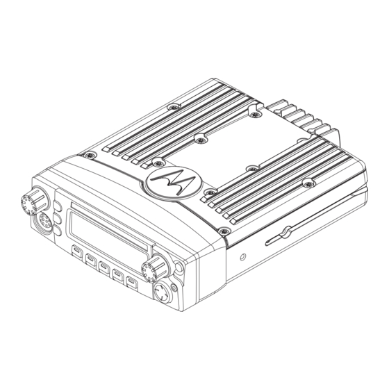
- Page 7 List of Figures List of Figures Figure 1-1. Front View of Dash Mount Transceiver Trunnion..............1-1 Figure 1-2. Side View of Dash Mount Transceiver Trunnion ..............1-1 Figure 1-3. Dash Mount Configuration ....................1-2 Figure 1-4. Remote Mount Configuration, with 110W transceiver............1-2 Figure 2-1.
-
Page 8: Mobile Radio Model Numbering Scheme
viii Mobile Radio Model Numbering Scheme Mobile Radio Model Numbering Scheme Typical Model Number: Position: Position 1 - Type of Unit M = Mobile Position 12 - Positions 2 & 3 - Model Series Unique Model Variations Model - XPR Series N = North America Position 4 - Frequency Band (Standard Package) -
Page 9: Commercial Warranty
Product Accessories One (1) Year Motorola, at its option, will at no charge either repair the Product (with new or reconditioned parts), replace it (with a new or reconditioned Product), or refund the purchase price of the Product during the warranty period provided it is returned in accordance with the terms of this warranty. Replaced parts or boards are warranted for the balance of the original applicable warranty period. -
Page 10: State Law Rights
Warranty service will be provided by Motorola through one of its authorized warranty service locations. If you first contact the company which sold you the Product, it can facilitate your obtaining warranty service. You can also call Motorola at 1-888-567-7347 US/Canada. -
Page 11: Patent And Software Provisions
A. that MOTOROLA will be notified promptly in writing by such purchaser of any notice of such claim; B. that MOTOROLA will have sole control of the defense of such suit and all negotiations for its settlement or compromise; and C. - Page 12 Commercial Warranty Notes March 23, 2006 6816812H01...
-
Page 13: Chapter 1 Introduction
Chapter 1 Introduction This manual covers the installation procedures for XPR 4300/4350/4500/4550 mobile and motorcycle radios with O5 control heads and accessories required to complete the radio system. The radio system consists of a control head, radio, antenna, microphone, speaker, cabling, and accessories. -
Page 14: Dash Mount Configuration
1.2.1 Dash Mount Configuration In the dash mounting version of the XPR 4300/4350/4500/4550, the control head is mounted on the front of the transceiver housing. Electrical connection between the two takes place within the radio via a flexible circuit board between the connectors on the front of the transceiver and at the back of the control head. -
Page 15: Tools Required For Xpr 4300/4350/4500/4550 Installations
Introduction: Tools Required for XPR 4300/4350/4500/4550 Installations Tools Required for XPR 4300/4350/4500/4550 Installations Tool Part Number 11/32 hex driver — RF cable tool HLN6695_ Regular slot screwdriver of — Phillips #2 Pin removal tool 6680163F01 1/4 hex driver — 6816812H01... - Page 16 Introduction This Page Is Intentionally Left Blank March 23, 2006 6816812H01...
-
Page 17: Chapter 2 Standard Configurations
The installation of this device should be completed by an authorized servicer or installer. 2.1.1 Installation Examples Your mobile two-way radio offers various methods of installation, including dash or remote mount. Except for 110W radios, all versions of the XPR 4300/4350/4500/4550 can be either dash or remote mounted (see Figure 2-1 through Figure 2-2). -
Page 18: Figure 2-3. Radio Installation (Dash Mount) With Transceiver
Standard Configurations: Planning the Installation 2.1.2 Wiring Diagrams Figure 2-3 shows the wiring diagrams for all the possible configurations. The title under each figure identifies the O5 control head configurations. Identify which of these figures shows the configuration that you are installing, and use the diagram when planning the installation. FUSE BATTERY RED LEAD... -
Page 19: Figure 2-4. Pin Configuration
Standard Configurations: Planning the Installation Figure 2-4. Pin Configuration 6816812H01 March 23, 2006... -
Page 20: Radio Mounting
Standard Configurations: Radio Mounting Radio Mounting CAUTION: DO NOT mount the radio on a plastic dashboard without first reinforcing the dashboard; the weight of the radio may crack or break the dashboard. CAUTION: DO NOT mount the radio on a flat or concave surface C a u t i o n where the radio could be partially submersed in water. -
Page 21: Figure 2-6. Transmission Hump Trunnion Mounting
Standard Configurations: Radio Mounting 2.2.1 Dash Mount with Trunnion 1. Select the location to mount your radio on the transmission hump (see Figure 2-6) or under the dash (see Figure 2-7). When mounting the trunnion on the transmission hump take care the transmission housing is not affected. -
Page 22: Locking Kit (Optional)
Standard Configurations: Power Cable 2.2.2 Locking Kit (Optional) 2.2.2.1 All Radios If an optional locking kit is used (shown in Figure 2-8), position the lock bottom housing on the trunnion before installing the radio mounting screws. Then slip the top lock housing on and remove the key. - Page 23 Standard Configurations: Power Cable 6816812H01 March 23, 2006...
-
Page 24: Ignition Sense Cable
Standard Configurations: Ignition Sense Cable Ignition Sense Cable Motorola supplies an ignition sense cable and recommends that it be used with every mobile installation. The ignition sense cable allows the radio to be turned on and off with the vehicle ignition switch, and allows the radio to “remember”... -
Page 25: Mini-Uhf Connection
The mini-UHF connector tool (Motorola part number HLN6695_) is designed to securely tighten the antenna plug–radio jack connection without damaging either the plug or the jack. -
Page 26: Speaker
2-10 Standard Configurations: Speaker 7. Give a final tug, by hand, to the collar, and retighten by hand as firmly as possible. 8. Slip the mini-UHF connector tool over the coaxial cable, using the gap between the tool’s legs (see Figure 2-31). -
Page 27: Figure 2-32. Speaker Mounting
Standard Configurations: Speaker 2-11 Trunnion Bracket Dashboard Firewall MAEPF-25764-O Figure 2-32. Speaker Mounting 6816812H01 March 23, 2006... -
Page 28: Microphone Hang-Up Clip
2-12 Standard Configurations: Microphone Hang-Up Clip Microphone Hang-Up Clip 2.7.1 Standard Hang-Up Clip The hang-up clip must be within reach of the operator(s). Measure this distance before actually mounting the bracket. Since the bracket has a positive-detent action, the microphone can be mounted in any position. -
Page 29: Chapter 3 Options And Accessories Installation
For dash-mounted configurations, the accessories must be installed through the accessory connector assembly that is located on the rear of the radio, adjacent to the power connector. Motorola-approved accessories are supplied with male terminals crimped to a 20-gauge wire specifically designed to fit the plug of the accessory connector assembly. -
Page 30: Mdc Emergency Pushbutton Or Footswitch Installation
Options and Accessories Installation: Dash-Mount Accessory Installation Insert the male terminal into the accessory connector assembly in the appropriate location and connect the accessory connector assembly in the rear accessory port (see Figure 3-8). Do not use other generic terminals in the plug. Generic terminals can cause electrical intermittencies and may cause damage to the plug. -
Page 31: Horn And Lights (External Alarm) Relay
Options and Accessories Installation: Dash-Mount Accessory Installation 3.2.2 Horn and Lights (External Alarm) Relay For installations that use the horn/lights option, select a suitable location for mounting (normally under the dash) and, referring to Figure 3-3, perform the following procedure: 1. -
Page 32: Table 3-1. Rear Accessory Jack Pin Functions
APCO accessories. The DC impedance is 660 ohms and the AC impedance is 560 ohms. Table 2-1 in Chapter 2 for wiring options. Note: Please see the XPR 4300/4350/4500/4550 Basic Service manual (Motorola publication part number 6816816H01) for more detailed descriptions of these pins. March 23, 2006... -
Page 33: Appendix A Replacement Parts Ordering
Crystal orders should specify the crystal type number, crystal and carrier frequency, and the model number in which the part is used. The XPR 4300/4350/4500/4550 Digital Mobile Radio Basic Service Manual (Motorola publication part number 6816816H01) includes complete parts lists and parts numbers. -
Page 34: Fax Orders
Replacement Parts Ordering: Telephone Orders Telephone Orders Radio Products and Services Division* (United States and Canada) 7:00 AM to 7:00 PM (Central Standard Time) Monday through Friday (Chicago, U.S.A.) 1-800-422-4210 1-847-538-8023 (International Orders) U.S. Federal Government Markets Division (USFGMD) 1-800-826-1913 Federal Government Parts - Credit Cards Only 8:30 AM to 5:00 PM (Eastern Standard Time) Fax Orders Radio Products and Services Division*... -
Page 35: Glossary
Glossary Glossary This glossary contains an alphabetical listing of terms and their definitions that are applicable to ASTRO portable and mobile subscriber radio products. Term Definition See analog-to-digital conversion. Abacus IC A custom integrated circuit providing a digital receiver intermediate frequency (IF) backend. - Page 36 Glossary-2 Term Definition See Customer Programming Software. Customer Software with a graphical user interface containing the feature set of an Programming ASTRO radio. Software See digital-to-analog conversion. See digital-to-analog converter. default A pre-defined set of parameters. digital Refers to data that is stored or transmitted as a sequence of discrete symbols from a finite set;...
- Page 37 Glossary-3 Term Definition firmware Code executed by an embedded processor such as the Host or DSP in a subscriber radio. This type of code is typically resident in non-volatile memory and as such is more difficult to change than code executed from RAM.
- Page 38 Data transmitted on the control channel from the central controller to the word subscriber unit. over-molded pad- A Motorola custom IC package, distinguished by the presence of solder array carrier balls on the bottom pads. March 23, 2006 6816812H01...
- Page 39 Glossary-5 Term Definition over-the-air rekeying Allows the dispatcher to remotely reprogram the encryption keys in the radio. Power amplifier. paging One-way communication that alerts the receiver to retrieve a message. Patriot IC A dual-core processor that contains an MCU and a DSP in one IC package.
- Page 40 Glossary-6 Term Definition real-time clock A module that keeps track of elapsed time even when a computer is turned off. receiver Electronic device that amplifies RF signals. A receiver separates the audio signal from the RF carrier, amplifies it, and converts it back to the original sound waves.
- Page 41 Glossary-7 Term Definition signal An electrically transmitted electromagnetic wave. Signal Qualifier An operating mode in which the radio is muted, but still continues to mode analyze receive data to determine RX signal type. softpot See software potentiometer. software Computer programs, procedures, rules, documentation, and data pertaining to the operation of a system.
- Page 42 Glossary-8 Term Definition Transmit. UART See also Universal Asynchronous Receiver Transmitter. Ultra-High Frequency. Universal A microchip with programming that controls a computer's interface to its Asynchronous attached serial devices. Receiver Transmitter Universal Serial Bus An external bus standard that supports data transfer rates of 12 Mbps. See Universal Serial Bus.
-
Page 43: Index
Index Index installation examples ..........2-1 radio dimensions ........... 1-1 trunnion ..............2-5 Numerics 100W radios emergency footswitch ........3-1, 3-2 configurations ............1-2 emergency pushbutton ........3-1, 3-2 external alarm see also Horn relay or Light relay accessories connector assembly ..........3-1 installing footswitch, emergency ........3-1, 3-2 dash mount ............3-1 emergency pushbutton ........3-1... - Page 44 Index-2 orange lead ............... 2-8 speaker ordering replacement parts ........A-1 connecting ............2-12 mounting ............ 2-10, 2-11 parts, ordering replacement ........A-1 tools, required ............1-3 functions ..............3-4 trunnion ground ..............3-1 below dash mounting ..........2-5 removal tool ............1-3 bracket for speaker ..........