Table of Contents
Advertisement
Quick Links
Advertisement
Table of Contents

Related Manuals for D-Link DGS-2000 Series


Summary of Contents for D-Link DGS-2000 Series
-
Page 2: Table Of Contents
Table of Contents D-Link DGS-2000 Series Ethernet Switch User Manual Table of Contents Table of Contents ............................. i About This Guide ............................. 1 Terms/Usage ..............................1 Copyright and Trademarks ..........................1 Product Introduction ........................... 2 DGS-2000-10 ..............................3 Front Panel ..............................3 Rear Panel .............................. -
Page 3: Table Of Contents
Table of Contents D-Link DGS-2000 Series Ethernet Switch User Manual Using Web-based Management ........................23 Supported Web Browsers ........................23 Connecting to the Switch .......................... 23 Login Web-based Management ....................... 23 Smart Wizard ............................... 24 Web-based Management ..........................24 D-Link Network Assistant ..........................24 Web-based Switch Configuration ...................... - Page 4 Table of Contents D-Link DGS-2000 Series Ethernet Switch User Manual System > System Log Configuration > System Log Settings ..............42 System > System Log Configuration > System Log Server ..............42 System > Time Profile ..........................43 System > Power Saving ........................... 43 System >...
- Page 5 Table of Contents D-Link DGS-2000 Series Ethernet Switch User Manual Configuration > DDM > DDM Vendor Info ....................76 Configuration > DULD > DULD Port Settings ..................76 Configuration > Multicast Forwarding & Filtering > Multicast Forwarding ..........76 Configuration > Multicast Forwarding & Filtering > Multicast Filter Mode ..........77 Configuration >...
- Page 6 Table of Contents D-Link DGS-2000 Series Ethernet Switch User Manual Monitoring > Errors > Received (RX) ..................... 104 Monitoring > Errors > Transmitted (TX)....................105 Monitoring > Cable Diagnostics ......................106 Monitoring > System Log ........................107 Monitoring > Browse ARP Table ......................107 Monitoring >...
- Page 7 Table of Contents D-Link DGS-2000 Series Ethernet Switch User Manual D-Link Green Technology ..................錯誤! 尚未定義書籤。 Appendix C – Rack mount Instructions ....................136...
-
Page 8: About This Guide
About This Guide D-Link DGS-2000 Series Ethernet Switch User Manual About This Guide This guide provides instructions to install the D-Link DGS-2000 series Ethernet Switch, and to configure Web-based Management step-by-step. Note: The model you have purchased may appear slightly different from the illustrations shown in the document. -
Page 9: Product Introduction
D-Link Green Technology includes a number of innovations to reduce energy consumption on DGS-2000 series such as shutting down a port, or turning off some LED indicators, or adjusting the power usage according to the Ethernet cable connected to it. -
Page 10: Dgs-2000-10
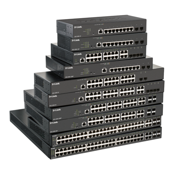
1 Product Introduction D-Link DGS-2000 Series Ethernet Switch User Manual the switches with other third-party devices for management in an SNMP-enabled environment. D-Link DGS- 2000 Series Ethernet Switches provides easy-to-use graphic interface and facilitates the operation efficiency. DGS-2000-10 8-Port 10/100/1000Mbps, plus 2 SFP Ports (100/1000Mbps) Ethernet switch. -
Page 11: Dgs-2000-10P
1 Product Introduction D-Link DGS-2000 Series Ethernet Switch User Manual DGS-2000-10P 8-Port 10/100/1000Mbps, plus 2 SFP Ports (100/1000Mbps) Ethernet PoE switch. Front Panel Figure 1.3 – DGS-2000-10P Front Panel The front panel of the DGS-2000-10P switch consists out of the following: •... -
Page 12: Rear Panel
1 Product Introduction D-Link DGS-2000 Series Ethernet Switch User Manual DNA3.x.x.x)) to download the image or call D-Link Technical Support for further help. Rear Panel Figure 1.4 – DGS-2000-10P Rear Panel Power: Connect the supplied AC power cable to this port. -
Page 13: Rear Panel
équivalent. NOTE: Once user enter in loader mode, you can use DNA tool (standalone version 2.0.2.4 only (No support by Chrome DNA3.x.x.x)) to download the image or call D-Link Technical Support for further help. Rear Panel Figure 1.6 –... -
Page 14: Rear Panel
UL,tension DC3.3V, classe laser NOTE: Once user enter in loader mode, you can use DNA tool (standalone version 2.0.2.4 only (No support by Chrome DNA3.x.x.x)) to download the image or call D-Link Technical Support for further help. Rear Panel Figure 1.8 –... -
Page 15: Rear Panel
UL,tension DC3.3V, classe laser NOTE: Once user enter in loader mode, you can use DNA tool (standalone version 2.0.2.4 only (No support by Chrome DNA3.x.x.x)) to download the image or call D-Link Technical Support for further help. Rear Panel Figure 1.10 –... -
Page 16: Rear Panel
UL,tension DC3.3V, classe laser NOTE: Once user enter in loader mode, you can use DNA tool (standalone version 2.0.2.4 only (No support by Chrome DNA3.x.x.x)) to download the image or call D-Link Technical Support for further help. Rear Panel Figure 1.12 –... -
Page 17: Rear Panel
équivalent. NOTE: Once user enter in loader mode, you can use DNA tool (standalone version 2.0.2.4 only (No support by Chrome DNA3.x.x.x)) to download the image or call D-Link Technical Support for further help. Rear Panel Figure 1.14 –... -
Page 18: Rear Panel
équivalent. NOTE: Once user enter in loader mode, you can use DNA tool (standalone version 2.0.2.4 only (No support by Chrome DNA3.x.x.x)) to download the image or call D-Link Technical Support for further help. Rear Panel Figure 1.16 –... -
Page 19: Front Panel
UL,tension DC3.3V, classe laser NOTE: Once user enter in loader mode, you can use DNA tool (standalone version 2.0.2.4 only (No support by Chrome DNA3.x.x.x)) to download the image or call D-Link Technical Support for further help. Rear Panel Figure 1.18 –... - Page 20 équivalent. NOTE: Once user enter in loader mode, you can use DNA tool (standalone version 2.0.2.4 only (No support by Chrome DNA3.x.x.x)) to download the image or call D-Link Technical Support for further help.
-
Page 21: Rear Panel
LED Indicators The Switch supports LED indicators for Power, Fan, and Link/Act for each port. The following shows the LED indicators for the DGS-2000 series Ethernet Switch along with an explanation of each indicator. Figure 1.21 –LED Indicators on DGS-2000 series... - Page 22 1 Product Introduction D-Link DGS-2000 Series Ethernet Switch User Manual Light off No link. Green Solid Light Power feeding. PoE Mode Amber Solid Light Error Condition. Solid Off No Power feeding. When there is a secure 1000Mbps Solid Ethernet connection (or link) at any Green of the ports.
-
Page 23: Hardware Installation
2 Hardware Installation D-Link DGS-2000 Series Ethernet Switch User Manual Hardware Installation This chapter provides unpacking and installation information for the D-Link DGS-2000 Series Ethernet Switch. Safety Cautions To reduce the risk of bodily injury, electrical shock, fire and damage to the equipment, observe the following precautions: •... -
Page 24: Step 1: Unpacking
2 Hardware Installation D-Link DGS-2000 Series Ethernet Switch User Manual • When connecting or disconnecting power to hot-pluggable power supplies, if offered with your system, observe the following guidelines: Install the power supply before connecting the power cable to the power supply. -
Page 25: Step 3: Plugging In The Ac Power Cord With Power Cord Clip
2 Hardware Installation D-Link DGS-2000 Series Ethernet Switch User Manual Figure 2.2 – Attach the mounting brackets to the Switch Then, use the screws provided with the equipment rack to mount the switch in the rack. Figure 2.3 – Mount the Switch in the rack or chassis... - Page 26 2 Hardware Installation D-Link DGS-2000 Series Ethernet Switch User Manual Figure 2.4 – Insert Tie Wrap to the Switch B) Plug the AC power cord into the power socket of the Switch. Figure 2.5 – Connect the power cord to the Switch C) Slide the Retainer through the Tie Wrap until the end of the cord.
- Page 27 2 Hardware Installation D-Link DGS-2000 Series Ethernet Switch User Manual D) Circle the tie of the Retainer around the power cord and into the locker of the Retainer. Figure 2.7 – Circle around the power cord E) Fasten the tie of the Retainer until the power cord is secured.
-
Page 28: Power Failure
As a precaution, the switch should be unplugged in case of power failure. When power is resumed, plug the switch back in. Grounding the Switch This section describes how to connect the DGS-2000 Series Switch to ground. You must complete this procedure before powering your switch. Required Tools and Equipment •... - Page 29 2 Hardware Installation D-Link DGS-2000 Series Ethernet Switch User Manual Le cordon d'alimentation de l'équipement doit être branché sur une prise de courant dotée d'une connexion à la terre.
-
Page 30: Getting Started
Getting Started This chapter introduces the management interface of D-Link DGS-2000 Series Ethernet Switch. Management Options The D-Link DGS-2000 Series Ethernet Switch can be managed through any port on the device by using the Web-based Management. Each switch must be assigned its own IP Address, which is used for communication with Web-Based Management or a SNMP network manager. -
Page 31: Smart Wizard
D-Link Network Assistant D-Link Network Assistant (DNA) is a program that is used to discover switches which are in the same layer 2 network segment as your PC. You can download the DNA utility from http://tools.dlink.com/intro/dna/. Please... -
Page 32: Web-Based Switch Configuration
Logout button first, then it will be seen as an abnormal exit and the login session will still be occupied. Finally, by clicking on the D-Link logo at the upper-left corner of the screen you will be redirected to the local D-Link website. -
Page 33: Tool Bar > Save Menu
4 Web-based Switch Configuration D-Link DGS-2000 Series Ethernet Switch User Manual Tool Bar > Save Menu The Save Menu provides Save Configuration and Save Log functions. Figure 4.2 – Save Menu Save Configuration Select to save the entire configuration changes to configuration ID 1 or 2 you have made to the device to switch’s non-volatile RAM. -
Page 34: Configuration Backup And Restore
4 Web-based Switch Configuration D-Link DGS-2000 Series Ethernet Switch User Manual Figure 4.7 – Tool Menu > Reboot Device Configuration Backup and Restore Allow the current configuration settings to be saved to a file (not including the password), and if necessary, you can restore configuration settings from this file. -
Page 35: Firmware Backup And Upgrade
4 Web-based Switch Configuration D-Link DGS-2000 Series Ethernet Switch User Manual Firmware Backup and Upgrade Allow for the firmware to be saved, or for an existing firmware file to be uploaded to the Switch. Two methods can be selected: HTTP or TFTP. -
Page 36: Tool Bar > Online Help
Tool Bar > Online Help The Online Help provides two ways of online support: D-Link Support Site will lead you to the D-Link website where you can find online resources such as updated firmware images; User Guide can offer an immediate reference for the feature definition or configuration guide. -
Page 37: System > System Settings
4 Web-based Switch Configuration D-Link DGS-2000 Series Ethernet Switch User Manual SNMP Status: Click Settings to link to SNMP > SNMP > SNMP Global Settings. Default is disabled. 802.1X Status: Click Settings to link to AAA > 802.1X > 802.1X Settings. Default is disabled. -
Page 38: System > Port Settings
4 Web-based Switch Configuration D-Link DGS-2000 Series Ethernet Switch User Manual server automatically on next boot up. To accomplish this, the DHCP server must deliver the TFTP server IP address and configuration file name information in the DHCP reply packet. The TFTP server must be up and running and store the necessary configuration file in its base directory when the request is received from the Switch. -
Page 39: System > Port Description
4 Web-based Switch Configuration D-Link DGS-2000 Series Ethernet Switch User Manual This switch provides a configurable MDI/MDIX function for users. The switches can be set as an MDI port in order to connect to other hubs or switches without an Ethernet crossover cable. -
Page 40: System > Ipv6 Setting > Ipv6 System Settings
4 Web-based Switch Configuration D-Link DGS-2000 Series Ethernet Switch User Manual Figure 4.21 – System > IP Interface Settings Interface Name: Specifies the name of IP interface. VLAN Name: Specifies the VLAN name of IP interface. IPv4 Address: Specifies the IPv4 address for the interface. -
Page 41: System > Snmp Settings > Snmp Global State
4 Web-based Switch Configuration D-Link DGS-2000 Series Ethernet Switch User Manual Neighbor IPv6 Address: Specifies the neighbor IPv6 address. Link Layer MAC Address: Specifies the link layer MAC address. Click Apply to make the configurations take effect. To search for all the current interfaces on the Switch, go to the second Interface Name field in the middle part of the window, tick the All check box. -
Page 42: System > Snmp Settings > Snmp Group Table
4 Web-based Switch Configuration D-Link DGS-2000 Series Ethernet Switch User Manual Priv-Protocol/Password: Specify either no authorization or DES 56-bit encryption and then enter a password for SNMPv3 encryption in the right column. Click Apply to create a new SNMP user account, and click Delete to remove any existing data. -
Page 43: System > Snmp Settings > Snmp Community Table
4 Web-based Switch Configuration D-Link DGS-2000 Series Ethernet Switch User Manual View Name: Name of the view, up to 32 characters. Subtree OID: The Object Identifier (OID) Subtree for the view. The OID identifies an object tree (MIB tree) that will be included or excluded from access by an SNMP manager. -
Page 44: System > Snmp Settings > Snmp Trap Settings
4 Web-based Switch Configuration D-Link DGS-2000 Series Ethernet Switch User Manual Figure 4.30 – System > SNMP Settings > SNMP Engine ID System > SNMP Settings > SNMP Trap Settings The SNMP Trap Settings page provide user to Specify whether the device can send SNMP notifications. -
Page 45: System > Mac Address Aging Time
4 Web-based Switch Configuration D-Link DGS-2000 Series Ethernet Switch User Manual Figure 4.32– System > User Accounts System > MAC Address Aging Time The MAC Address Aging Time page specifies the length of time a learned MAC Address will remain in the forwarding table without being accessed (that is, how long a learned MAC address is allowed to remain idle). -
Page 46: System > Web Settings
4 Web-based Switch Configuration D-Link DGS-2000 Series Ethernet Switch User Manual Figure 4.35 – System > PPPoE Circult ID Insertion Settings PPPoE Circuit ID Insertion State: Enable or disable the PPPoE circuit insertion state, and Click Apply to make the configurations take effect. -
Page 47: System > Ssh Settings
Click Apply to make the configurations take effect. System > D-Link Discover Protocol Settings For the D-Link Discovery Protocol (DDP) supported device, this page is an option for user to disable DDP or configure the DDP packet report timer. D-Link Discover Protocol State: The default setting is Disabled. -
Page 48: System > Trace Route
4 Web-based Switch Configuration D-Link DGS-2000 Series Ethernet Switch User Manual Figure 4.40 – System > Ping Test Target IP address allows both IPv4 and IPv6 addresses format. The time of ping can be configured in Repeat Pinging filed; Infinite and range of 1-255 are available options to use. -
Page 49: System > System Log Configuration > System Log Settings
4 Web-based Switch Configuration D-Link DGS-2000 Series Ethernet Switch User Manual Interval (1-2147483647 sec): The time in seconds between notifications. History Size (1-500): The maximum number of entries listed in the history log used for notification. Up to 500 entries can be specified. -
Page 50: System > Time Profile
4 Web-based Switch Configuration D-Link DGS-2000 Series Ethernet Switch User Manual Facility: Specifies an application from which system logs are sent to the remote server. Only one facility can be assigned to a single server. If a second facility level is assigned, the first facility is overwritten. There are up to eight facilities can be assigned (Local 0 ~ Local 7). -
Page 51: System > Ieee802.3Az Eee Settings
4 Web-based Switch Configuration D-Link DGS-2000 Series Ethernet Switch User Manual Advanced Power Saving Settings: Type: Specifies the Power Saving type to be LED Shut-off, Port Shut-off, Port Standby or System Hibernation. LED Shut-off - The LED Shut-off gets high priority. If the user select LED Shut-off, the profile function will not take effect. - Page 52 4 Web-based Switch Configuration D-Link DGS-2000 Series Ethernet Switch User Manual The IEEE 802.1Q VLAN Configuration page provides powerful VID management functions. The original settings have the VID as 1, no default name, and all ports as “Untagged” Rename: Click to rename the VLAN group.
-
Page 53: Configuration > 802.1Q Vlan Pvid
4 Web-based Switch Configuration D-Link DGS-2000 Series Ethernet Switch User Manual Figure 4.50 – Configuration > 802.1Q VLAN > Add VLAN Click the VID number, the configuration of VLAN group which selected by user will displayed. Change the port assignment then click Apply to implement changes made. - Page 54 4 Web-based Switch Configuration D-Link DGS-2000 Series Ethernet Switch User Manual Figure 4.53 – VLAN > Voice VLAN > Voice VLAN Global Settings Voice VLAN: Select to enable or disable Voice VLAN. The default is Disabled. After you enabled Voice VLAN, you can configure the Voice VLAN Global Settings.
-
Page 55: Configuration > Voice Vlan > Voice Vlan Port Settings
4 Web-based Switch Configuration D-Link DGS-2000 Series Ethernet Switch User Manual Note: Voice VLAN has higher priority than any other features (including QoS). Therefore the voice traffic will be operated according to the Voice VLAN setting and not impacted by the QoS feature. -
Page 56: Configuration > Voice Vlan > Voice Device List
4 Web-based Switch Configuration D-Link DGS-2000 Series Ethernet Switch User Manual Configuration > Voice VLAN > Voice Device List The Voice Device List page displays the information of Voice VLAN. Figure 4.55 – VLAN > Voice VLAN > Voice Device List Select a port or all ports and click Search to display the Voice Device information in the table. -
Page 57: Configuration > Auto Surveillance Vlan > Mac Settings And Surveillance Device
Similar as Voice VLAN, Auto Surveillance VLAN is a feature that allows you to automatically place the video traffic from D-Link IP cameras to an assigned VLAN to enhance the IP surveillance service. With a higher priority and individual VLAN, the quality and the security of surveillance traffic are guaranteed. The Auto Surveillance VLAN function will check the source MAC address / VLAN ID on the incoming packets. -
Page 58: Configuration > Auto Surveillance Vlan > Onvif Nvr Information
4 Web-based Switch Configuration D-Link DGS-2000 Series Ethernet Switch User Manual Figure 4.59 – VLAN > Auto Surveillance VLAN > ONVIF IPC Information Configuration > Auto Surveillance VLAN > ONVIF NVR Information The ONVIF (Open Network Video Interface Forum) NVR Information page displays the information on each NVR connected to the switch. -
Page 59: Configuration > Qinq > Vlan Translation Settings
4 Web-based Switch Configuration D-Link DGS-2000 Series Ethernet Switch User Manual Role: The user can choose between UNI or NNI role. UNI – To select a user-network interface which specifies that communication between the specified user and a specified network will occur. -
Page 60: Configuration > Link Aggregation > Port Trunkings
4 Web-based Switch Configuration D-Link DGS-2000 Series Ethernet Switch User Manual Configuration > Link Aggregation > Port Trunkings The Port Trunkings function enables the combining of two or more ports together to increase bandwidth. Up to eight Trunk groups may be created, and each group consists up to eight ports. Select Enabled and click Apply to active the Link Aggregation State. -
Page 61: Configuration > Igmp Snooping > Igmp Snooping
IGMP snooping can help reduce cluttered traffic on the LAN. With IGMP snooping enabled globally, the DGS-2000 Series Ethernet Switch will forward multicast traffic only to connections that have group members attached. The settings of IGMP snooping is set by each VLAN individually. - Page 62 4 Web-based Switch Configuration D-Link DGS-2000 Series Ethernet Switch User Manual learned host entry will be purged from the multicast group. The default value is 260 seconds. Router Timeout This is the interval after which a learned router port entry will be purged.
- Page 63 4 Web-based Switch Configuration D-Link DGS-2000 Series Ethernet Switch User Manual a group. Default is 1 second. The Max Response Time specifies the maximum allowed time before sending a responding report message. Adjusting this setting effects the Max Response Time "leave latency", or the time between the moment the last host leaves a group...
-
Page 64: Configuration > Igmp Snooping > Igmp Access Control Settings
4 Web-based Switch Configuration D-Link DGS-2000 Series Ethernet Switch User Manual Figure 4.68– Configuration > IGMP Snooping > IGMP Snooping-Multicast Entry Table Configuration > IGMP Snooping > IGMP Access Control Settings The IGMP Access Control Settings page is used to enable or disable the IGMP access control of selected ports. -
Page 65: Configuration > Mld Snooping > Mld Snooping Settings
4 Web-based Switch Configuration D-Link DGS-2000 Series Ethernet Switch User Manual Click the Find button to locate a specific entry based on the information entered. Configuration > MLD Snooping > MLD Snooping Settings The MLD Snooping Settings page allows user to configure the max multicast group for IGMP Snooping. -
Page 66: Configuration > Jumbo Frame
Figure 4.75 - Configuration > IGMP Snooping > ISM VLAN Settings Configuration > Jumbo Frame D-Link Gigabit Ethernet Switches support jumbo frames (frames larger than the Ethernet frame size of 1536 bytes) of up to 10000 bytes (tagged). Default is disabled, Select Enabled then click Apply to turn on the... -
Page 67: Configuration > Port Mirroring
4 Web-based Switch Configuration D-Link DGS-2000 Series Ethernet Switch User Manual Figure 4.76 – L2 Functions > Jumbo Frame Configuration > Port Mirroring Port Mirroring is a method of monitoring network traffic that forwards a copy of each incoming and/or outgoing packet from one port of the Switch to another port, where the packet can be studied. -
Page 68: Configuration > Sntp Settings > Time Settings
4 Web-based Switch Configuration D-Link DGS-2000 Series Ethernet Switch User Manual Figure 4.78 – L2 Functions > Loopback Detection Loopback Detection: Use the drop-down menu to enable or disable loopback detection. The default is Disabled. Mode: Specifies Port-based or VLAN-based mode. If port-based mode is selected, the loop happening port will be shut down and affect all member VLANs. -
Page 69: Configuration > Sntp Settings > Timezone Settings
4 Web-based Switch Configuration D-Link DGS-2000 Series Ethernet Switch User Manual Figure 4.79 – Configuration > SNTP Settings > Time Settings Clock Source: Specify the clock source by which the system time is set. The possible options are: Local - Indicates that the system time is set locally by the device. -
Page 70: Configuration > Dhcp Relay > Dhcp Relay Global Settings
4 Web-based Switch Configuration D-Link DGS-2000 Series Ethernet Switch User Manual Daylight Saving Time State: Enable or disable the DST Settings. Daylight Saving Time Offset: Use this drop-down menu to specify the amount of time that will constitute the local DST offset - 30, 60, 90, or 120 minutes. - Page 71 4 Web-based Switch Configuration D-Link DGS-2000 Series Ethernet Switch User Manual seconds field of the BOOTP or DHCP packet. If a non-zero value is entered, the Switch will use that value, along with the hop count to determine whether to forward a given BOOTP or DHCP packet.
-
Page 72: Configuration > Dhcp Relay > Dhcp Relay Interface Settings
4 Web-based Switch Configuration D-Link DGS-2000 Series Ethernet Switch User Manual situation, user should disable the information-check feature so that the switch does not remove the option-82 field from the packet. User can configure the action that the switch takes when it receives a packet with existing option-82 information by configuring the DHCP Agent Information Option 82 Policy. -
Page 73: Configuration > Dhcpv6 Relay Settings
4 Web-based Switch Configuration D-Link DGS-2000 Series Ethernet Switch User Manual Click Apply to make the configurations take effect Configuration > DHCPv6 Relay Settings The DHCPv6 Relay Settings page allows user to configure the DHCPv6 settings. Figure 4.84 - Configuration > DHCPv6 Relay Settings DHCPv6 Relay Status: Specifies whether DHCPv6 Relay is enabled on the device. - Page 74 4 Web-based Switch Configuration D-Link DGS-2000 Series Ethernet Switch User Manual By default, Rapid Spanning Tree is disabled. If enabled, the Switch will listen for BPDU packets and its accompanying Hello packet. BPDU packets are sent even if a BPDU packet was not received. Therefore, each link between bridges is sensitive to the status of the link.
-
Page 75: Configuration > Spanning Tree > Stp Port Settings
4 Web-based Switch Configuration D-Link DGS-2000 Series Ethernet Switch User Manual packet and the information held for the port will age out. The user may set a hop count from 6 to 40. The default is 20. Root Bridge: Displays the MAC address of the Root Bridge. -
Page 76: Configuration > Spanning Tree > Mst Configuration Identification
4 Web-based Switch Configuration D-Link DGS-2000 Series Ethernet Switch User Manual port normally should not receive BPDU packets. If a BPDU packet is received, it automatically loses edge port status. Selecting the False parameter indicates that the port does not have edge port status. Selecting the Auto parameter indicates that the port have edge port status or not have edge port status automatically. -
Page 77: Configuration > Spanning Tree > Stp Instance Settings
4 Web-based Switch Configuration D-Link DGS-2000 Series Ethernet Switch User Manual MSTI ID (1-15): Enter a number between 1 and 15 to set a new MSTI on the Switch. Type: This field allows the user to choose a desired method for altering the MSTI settings. -
Page 78: Configuration > 802.3Ah Ethernetlink Oam > Ethernet Oam Port Settings
4 Web-based Switch Configuration D-Link DGS-2000 Series Ethernet Switch User Manual Figure 4.89 - Configuration > Spanning Tree > MST Port Information Instance ID: Displays the MSTI ID of the instance being configured. An entry of 0 in this field denotes the CIST (default MSTI). -
Page 79: Configuration > Ddm > Ddm Settings
4 Web-based Switch Configuration D-Link DGS-2000 Series Ethernet Switch User Manual Figure 4.91 - Configuration > Ethernet OAM > Ethernet OAM Event Configuration From Port / To Port: Select a range of ports to be configured. Link Event: Select the link event, Link Monitor or Critical Link Event. -
Page 80: Configuration > Ddm > Ddm Temperature Settings
4 Web-based Switch Configuration D-Link DGS-2000 Series Ethernet Switch User Manual Configuration > DDM > DDM Temperature Settings The DDM Temperature Threshold Settings page allows user to configure the DDM temperature threshold for specific ports on the Switch. Figure 4.93 - Configuration > DDM > DDM Temperature Settings Port: Specifies the port to be configured. -
Page 81: Configuration > Ddm > Ddm Bias Current Threshold Settings
4 Web-based Switch Configuration D-Link DGS-2000 Series Ethernet Switch User Manual Low Warning: Specifies the low threshold for the warning. When the operating Voltage falls below the configured value, the action associated with the warning is taken. Vaule (0 – 6.55): Specifies the value for the specified type of port. -
Page 82: Configuration > Ddm > Ddm Rx Power Threshold Settings
4 Web-based Switch Configuration D-Link DGS-2000 Series Ethernet Switch User Manual High Alarm: Specifies the high threshold for the alarm. When the TX power threshold rises above the configured value, the action associated with the alarm is taken. Low Alarm: Specifies the low threshold for the alarm. When the TX power threshold falls below the configured value, the action associated with the alarm is taken. -
Page 83: Configuration > Ddm > Ddm Vendor Info
4 Web-based Switch Configuration D-Link DGS-2000 Series Ethernet Switch User Manual Figure 4.98 - Configuration > DDM > DDM Status Table Configuration > DDM > DDM Vendor Info The DDM Vendor Info page displays the current vendor’s operating digital diagnostic monitoring parameters and their values on the SFP module for specified ports. -
Page 84: Configuration > Multicast Forwarding & Filtering > Multicast Filter Mode
4 Web-based Switch Configuration D-Link DGS-2000 Series Ethernet Switch User Manual Figure 4.101 - Configuration > Multicast Forwarding & Filter > Multicast Forwarding VID: Specify the VID Multicast MAC Address: Specify the multicast address. Egress: Click the Port Number for multicast traffic. -
Page 85: Configuration > Multicast Forwarding & Filtering > Limited Multicast Range Settings
4 Web-based Switch Configuration D-Link DGS-2000 Series Ethernet Switch User Manual Profile ID: Specify the Profile ID. Profile Name: Specify the Profile Name. Click Add to create a new IP Multicast Profile or click Delete All to clear all the entries. -
Page 86: Qos > Traffic Control
4 Web-based Switch Configuration D-Link DGS-2000 Series Ethernet Switch User Manual From Port / To Port: Specify the port ranges to be configured. IP Type: Specify the IP type is IPv4 or IPv6. Max Group (1-32): Specify the Max Group to be configured. -
Page 87: Qos > Bandwidth Control
4 Web-based Switch Configuration D-Link DGS-2000 Series Ethernet Switch User Manual down the port that is experiencing a traffic storm. This parameter is only useful for ports configured as Shutdown in their Action field and therefore will not operate for Hardware based Traffic Control implementations. -
Page 88: Qos > Qos Settings
4 Web-based Switch Configuration D-Link DGS-2000 Series Ethernet Switch User Manual Figure 4.107 – QoS > Bandwidth Control From Port / To Port: A consecutive group of ports may be configured starting with the selected port. Type: This drop-down menu allows user to select between RX (receive), TX (transmit), and Both. This setting will determine whether the bandwidth ceiling is applied to receiving, transmitting, or both receiving and transmitting packets. -
Page 89: Rmon > Rmon Basic Settings
4 Web-based Switch Configuration D-Link DGS-2000 Series Ethernet Switch User Manual Figure 4.108 – QoS > QoS Setting Select QoS Mode: Select QoS mode from options “Port Base”, “802.1P” and “DSCP” Queuing mechanism: Select options from “Strict Priority” and “WRR”... -
Page 90: Rmon > Rmon Alarm Configuration
4 Web-based Switch Configuration D-Link DGS-2000 Series Ethernet Switch User Manual Owner: Displays the RMON station or user that requested the RMON information. Click Apply to make the configurations take effect. RMON > RMON Alarm Configuration The RMON Alarm Configuration page allows the user to configure the network alarms. Network alarms occur when a network problem, or event, is detected. -
Page 91: Security > Trusted Host
To delete the IP address, simply click the Delete button. Check the unwanted address, and then click Apply. Security > Safeguard Engine D-Link’s Safeguard Engine is a robust and innovative technology that automatically throttles the impact of packet flooding into the switch's CPU. This function helps protect the Switch from being interrupted by malicious viruses or worm attacks. -
Page 92: Security > Port Security Fdb Entry
4 Web-based Switch Configuration D-Link DGS-2000 Series Ethernet Switch User Manual A given ports’ (or a range of ports') dynamic MAC address learning can be stopped such that the current source MAC addresses entered into the MAC address forwarding table cannot be changed once the port is enabled. - Page 93 4 Web-based Switch Configuration D-Link DGS-2000 Series Ethernet Switch User Manual user name) with the client, and forward it to another remote RADIUS authentication server to verify access rights. The EAP packet from the RADIUS server also contains the authentication method to be used. The client can reject the authentication method and request another, depending on the configuration of the client software and the RADIUS server.
-
Page 94: Security > 802.1X > 802.1X User
4 Web-based Switch Configuration D-Link DGS-2000 Series Ethernet Switch User Manual If ForceUnauthorized is selected, the port will remain in the unauthorized state, ignoring all attempts by the client to authenticate. The Switch cannot provide authentication services to the client through the interface. -
Page 95: Security > 802.1X > 802.1X Guest Vlan
4 Web-based Switch Configuration D-Link DGS-2000 Series Ethernet Switch User Manual Figure 4.121 - Security > 802.1X > 802.1X Authentication RUDIUS Index: Choose the desired RADIUS server to configure: 1, 2 or 3. IP Address: Select IPv4 or IPv6 and enter the IP address. -
Page 96: Security > Mac Address Table > Static Mac
4 Web-based Switch Configuration D-Link DGS-2000 Series Ethernet Switch User Manual Security > MAC Address Table > Static MAC Allow user to create static MAC address entry into forwarding table. This feature usually used in the port connected to certain devices that are permanent used in network, for example: DHCP servers, syslog server, network gateway location, etc. -
Page 97: Security > Access Authentication Control > Application Authentication Settings
4 Web-based Switch Configuration D-Link DGS-2000 Series Ethernet Switch User Manual will have to wait 60 seconds before another authentication attempt. Telnet and web users will be disconnected from the Switch. The user may set the number of attempts from 1 to 255. The default setting is Click Apply to make the configurations take effect. -
Page 98: Security > Access Authentication Control > Authentication Server
4 Web-based Switch Configuration D-Link DGS-2000 Series Ethernet Switch User Manual Figure 4.128 – Security > Access Authentication control > Authentication Server Group-Edit Select Group Name, Protocol and IP address then click Add to implement the changes. NOTE: The user must configure Authentication Server Hosts using the Authentication Server Hosts page before adding hosts to the list. -
Page 99: Security > Access Authentication Control > Login Method Lists
4 Web-based Switch Configuration D-Link DGS-2000 Series Ethernet Switch User Manual Timeout (1 - 255): Enter the time in seconds the Switch will wait for the server host to reply to an authentication request. The default value is 5 seconds. -
Page 100: Security > Access Authentication Control > Local Enable Password Settings
4 Web-based Switch Configuration D-Link DGS-2000 Series Ethernet Switch User Manual Figure 4.131 – Security > Access Authentication control > Enable Method Lists To define an Enable Login Method List, set the following parameter and click Apply: Method List Name: Enter a method list name defined by the user of up to 15 characters. -
Page 101: Security > Dos Prevention Settings
4 Web-based Switch Configuration D-Link DGS-2000 Series Ethernet Switch User Manual Figure 4.133 – Security > Traffic Segmentation To configure traffic segmentation specify a port or All ports from the switch, using the Port pull-down menu and select Port Map then click Apply to enter the settings into the Switch’s Traffic Segmentation table. -
Page 102: Security > Smart Binding > Smart Binding
4 Web-based Switch Configuration D-Link DGS-2000 Series Ethernet Switch User Manual Figure 4.135 – Security > Smart Binding > Smart Binding Settings The Smart Binding Settings page contains the following fields: From Port/ To Port: Select a range of ports to set for IP-MAC-port binding. -
Page 103: Security > Smart Binding > White List
4 Web-based Switch Configuration D-Link DGS-2000 Series Ethernet Switch User Manual Figure 4.136 – Security > Smart Binding > Smart Binding The Manual Binding Settings contains the following fields: From Port / To Port: Specifies the port ranges for MAC address to bind to the IP address of Binding list. -
Page 104: Security > Smart Binding > Dhcp Snooping List
4 Web-based Switch Configuration D-Link DGS-2000 Series Ethernet Switch User Manual Figure 4.138 – Security > Smart Binding > Black List By giving conditions, desired devices information can be screened out below then click Find to search for a list of the entry: VID: Enter the VLAN ID number of the device. -
Page 105: Monitoring > Session Table
4 Web-based Switch Configuration D-Link DGS-2000 Series Ethernet Switch User Manual Figure 4.141 – Monitoring > Port Statistics Previous Page: Go back to the Statistics main page. Refresh: To renew the details collected and displayed. Clear Counter: To reset the details displayed. -
Page 106: Monitoring > Memory Utilization
4 Web-based Switch Configuration D-Link DGS-2000 Series Ethernet Switch User Manual Monitoring > Memory Utilization The Memory Utilization displays the percentage of the memory being used, expressed as an integer percentage and calculated as a simple average by time interval. Click Apply to implement the configured settings. -
Page 107: Monitoring > Packet Size
4 Web-based Switch Configuration D-Link DGS-2000 Series Ethernet Switch User Manual The user may use the real-time graphic of the Switch at the top of the web page to view utilization statistics per port by clicking on a port. Click Apply to make the configurations take effect. The following field can be set: Time Interval: Select the desired setting between 1s and 60s, where "s"... -
Page 108: Monitoring > Packets > Transmitted (Tx)
4 Web-based Switch Configuration D-Link DGS-2000 Series Ethernet Switch User Manual 65-127: The total number of packets (including bad packets) received that were between 65 and 127 octets in length inclusive (excluding framing bits but including FCS octets). 128-255: The total number of packets (including bad packets) received that were between 128 and 255 octets in length inclusive (excluding framing bits but including FCS octets). -
Page 109: Monitoring > Packets > Received (Rx)
4 Web-based Switch Configuration D-Link DGS-2000 Series Ethernet Switch User Manual The following fields can be set or viewed: Time Interval: Select the desired setting between 1s and 60s, where “s” stands for seconds. The default value is one second. -
Page 110: Monitoring > Packets > Umb Cast (Rx)
4 Web-based Switch Configuration D-Link DGS-2000 Series Ethernet Switch User Manual The following fields can be set or viewed: Time Interval: Select the desired setting between 1s and 60s, where “s” stands for seconds. The default value is one second. -
Page 111: Monitoring > Errors > Received (Rx)
4 Web-based Switch Configuration D-Link DGS-2000 Series Ethernet Switch User Manual The following fields can be set or viewed: Time Interval: Select the desired setting between 1s and 60s, where “s” stands for seconds. The default value is one second. -
Page 112: Monitoring > Errors > Transmitted (Tx)
4 Web-based Switch Configuration D-Link DGS-2000 Series Ethernet Switch User Manual UnderSize: The number of packets detected that are less that the minimum permitted packets size of 64 bytes and have a good CRC. Undersize packets usually indicate collision fragments, a normal network occurrence. -
Page 113: Monitoring > Cable Diagnostics
4 Web-based Switch Configuration D-Link DGS-2000 Series Ethernet Switch User Manual ExDefet: Counts the number of packets for which the first transmission attempt on a particular interface was delayed because the medium was busy. CRC Error: Counts otherwise valid packets that did not end on a byte (octet) boundary. -
Page 114: Monitoring > System Log
4 Web-based Switch Configuration D-Link DGS-2000 Series Ethernet Switch User Manual ports only. The definition of cable pair is listed below: Pair1: PIN4, PIN5 Pair2: PIN1, PIN2 Pair3: PIN3, PIN6 Pair4: PIN7, PIN8 Monitoring > System Log The System Log page provides information about system logs, including information when the device was booted, how the ports are operating, when users logged in, when sessions timed out, as well as other system information. -
Page 115: Monitoring > Ethernet Oam > Browse Ethernet Oam Statistics
4 Web-based Switch Configuration D-Link DGS-2000 Series Ethernet Switch User Manual Figure 4.161 - Monitoring > Ethernet OAM > Browse Ethernet OAM Event Log Port: Select the port to be viewed. Port List: Enter a list of ports. Tick the All Ports check box to select all ports. -
Page 116: Monitoring > Igmp Snooping > Igmp Snooping Host
4 Web-based Switch Configuration D-Link DGS-2000 Series Ethernet Switch User Manual VLAN Name: Specify the name of the VLAN for which to be displayed the IGMP Snooping Group nformation. VID: Specify the list of the VLAN IDs for which to be displayed the IGMP Snooping Group information. -
Page 117: Monitoring > Port Access Control > Radius Authentication
4 Web-based Switch Configuration D-Link DGS-2000 Series Ethernet Switch User Manual Monitoring > Port Access Control > RADIUS Authentication This table contains information concerning the activity of the RADIUS authentication client on the client side of the RADIUS authentication protocol. It has one row for each RADIUS authentication server that the client shares a secret with. -
Page 118: Acl > Acl Configuration Wizard
4 Web-based Switch Configuration D-Link DGS-2000 Series Ethernet Switch User Manual Figure 4.167 - Monitoring > Port Access Control > RADIUS Account Client The user may also select the desired time interval to update the statistics, between 1s and 60s, where “s”... - Page 119 4 Web-based Switch Configuration D-Link DGS-2000 Series Ethernet Switch User Manual Figure 4.168 - ACL > ACL Configuration Wizard From: Specify the origin of accessible packets. The possible values are: Any - Indicates ACL action will be on packets from any source.
-
Page 120: Acl > Access Profile List
4 Web-based Switch Configuration D-Link DGS-2000 Series Ethernet Switch User Manual failed. ACL > Access Profile List The Access Profile List provides information for configuring ACL Profiles manually. ACL profiles are attached to interfaces, and define how packets are forwarded if they match the ACL criteria. -
Page 121: Acl > Acl Finder
4 Web-based Switch Configuration D-Link DGS-2000 Series Ethernet Switch User Manual NOTE: Unable to select Payload in a MAC ACL, or L2 Header in IP ACL. 3) After the Profile ID has been created, it will go back to the main Access Profile List page. -
Page 122: Acl > Cpu Filter Access Profile List
4 Web-based Switch Configuration D-Link DGS-2000 Series Ethernet Switch User Manual TCP All - Indicates CPU Filter action will be on all TCP Packets. TCP Source Port - Take effect if TCP Source Port matches. TCP Destination Port - Take effect if TCP Destination Port matches. -
Page 123: Acl > Cpu Filter Finder
DGS-2000-10P/10MP/28P/28MP/52MP works with all D-Link 802.3af or 802.3at capable devices. The Switch also works in PoE mode with all non-802.3af capable D-Link AP, IP Cam and IP phone equipment via the PoE splitter DWL-P50. IEEE 802.3at defined that the PSE provides power according to the following classification:... - Page 124 4 Web-based Switch Configuration D-Link DGS-2000 Series Ethernet Switch User Manual model of DGS-2000/ME series: Model 802.3at compliance port System Budget DGS-2000-10P 65 Watts DGS-2000-10MP 130 Watts DGS-2000-28P 1-24 193 Watts DGS-2000-28MP 1-24 370 Watts DGS-2000-52MP 370 Watts Figure 4.176 – PoE > PoE Port Settings...
-
Page 125: Poe > Poe System Settings (Dgs-2000-10P/10Mp/28P/28Mp/52Mp Only)
4 Web-based Switch Configuration D-Link DGS-2000 Series Ethernet Switch User Manual Class 2: Specifies that the power limit will be set to 7W Class 3: Specifies that the power limit will be set to 15.4W Class 4: For 802.3at compliance PD devices. Supports up to 30W in this class. -
Page 126: Lldp > Basic Lldp Port Settings
4 Web-based Switch Configuration D-Link DGS-2000 Series Ethernet Switch User Manual Figure 4.178 – LLDP > LLDP Global Settings LLDP: When this function is Enabled, the switch can start to transmit, receive and process the LLDP packets. For the advertisement of LLDP packets, the switch announces the information to its neighbor through ports. -
Page 127: Lldp > 802.1 Extension Lldp Port Settings
4 Web-based Switch Configuration D-Link DGS-2000 Series Ethernet Switch User Manual Port Description: Specifies whether the Port Description TLV is enabled on the port. The possible field values are: Enabled – Enables the Port Description TLV on the port. Disabled – Disables the Port Description TLV on the port. -
Page 128: Lldp > Lldp Management Address Settings
4 Web-based Switch Configuration D-Link DGS-2000 Series Ethernet Switch User Manual Figure 4.181 – LLDP > 802.3 Extension LLDP Port Settings From Port/To Port: A consecutive group of ports may be configured starting with the selected port. MAC/PHY Configuration/Status: Specifies whether the MAC/PHY Configuration Status is enabled on the port. -
Page 129: Lldp > Lldp Statistics Table
4 Web-based Switch Configuration D-Link DGS-2000 Series Ethernet Switch User Manual LLDP > LLDP Statistics Table The LLDP Statistics page displays an overview of all LLDP traffic. Figure 4.183 – LLDP > LLDP Statistics Table The following information can be viewed: LLDP Statistics System: Displays the counters that refer to the whole switch. -
Page 130: Lldp > Lldp Local Port Table
4 Web-based Switch Configuration D-Link DGS-2000 Series Ethernet Switch User Manual Management Address: Specifies IPv4 or IPv6 address then enter the address. Click Search and the table will update and display the values required. Subtype: Displays the managed address subtype. For example, MAC or IPv4. -
Page 131: Lldp > Lldp Remote Port Table
4 Web-based Switch Configuration D-Link DGS-2000 Series Ethernet Switch User Manual Figure 4.187 – LLDP > LLDP Local Port Detailed Table LLDP > LLDP Remote Port Table This LLDP Remote Port Table page is used to display the LLDP Remote Port Brief Table. Select port number and click Search to display additional information. -
Page 132: Lldp > Lldp-Med Settings
4 Web-based Switch Configuration D-Link DGS-2000 Series Ethernet Switch User Manual Figure 4.189 – LLDP > LLDP Remote Port Normal Table To view the detail settings for a remote port, click View Detailed and the following page displays. Figure 4.190 – LLDP > LLDP Remote Port Detailed Table LLDP >... -
Page 133: L3 Functions > Ipv4 Static Route
4 Web-based Switch Configuration D-Link DGS-2000 Series Ethernet Switch User Manual Figure 4.191 – LLDP > LLDP –MED Settings L3 Functions > IPv4 Static Route By The Switch supports static routing for IPv4 formatted addressing. User can create up to 256 static route entries for IPv4. -
Page 134: L3 Functions > Ipv4 Routing Table Finder
4 Web-based Switch Configuration D-Link DGS-2000 Series Ethernet Switch User Manual L3 Functions > IPv4 Routing Table Finder The IPv4 routing table stores all the external routes information of the Switch. The IPv4 Routing Table Finder page displays all the routing information on the Switch. - Page 135 4 Web-based Switch Configuration D-Link DGS-2000 Series Ethernet Switch User Manual Network Address; Specifies the destination network address of the route to be displayed. Click Search to display the information of specified route entry.
-
Page 136: Appendix A - Ethernet Technology
Appendix A - Ethernet Technology D-Link DGS-2000 Series Ethernet Switch User Manual Appendix A - Ethernet Technology This chapter will describe the features of the D-Link DGS-2000 Series Ethernet Switch and provide some background information about Ethernet/Fast Ethernet/Gigabit Ethernet switching technology. Gigabit Ethernet Technology Gigabit Ethernet is an extension of IEEE 802.3 Ethernet utilizing the same packet structure, format, and... -
Page 137: Appendix B - Technical Specifications
Appendix B - Technical Specifications D-Link DGS-2000 Series Ethernet Switch User Manual Appendix B - Technical Specifications This appendix contains the device specifications, and contains the topics: • Hardware Specifications • Features Hardware Specifications Key Components / Performance DGS-2000-10: 20Gbps... - Page 138 Appendix B - Technical Specifications D-Link DGS-2000 Series Ethernet Switch User Manual Ethernet ports 2000-10MP 20 x 10/100/1000BaseT ports for DGS-2000-20 24 x 10/100/1000BaseT ports for DGS-2000-26 28 x 10/100/1000BaseT ports for DGS-2000-28, DGS-2000-28P, DGS-2000- 28MP 52 x 10/100/1000BaseT ports for DGS-2000-52, DGS-2000-52MP 1000Base-T ports compliant to following standards: - IEEE 802.3 compliance...
- Page 139 Appendix B - Technical Specifications D-Link DGS-2000 Series Ethernet Switch User Manual WDM Transceivers Supported: - DEM-220T (100Base-BX,TX-1550/RX-1310nm, 20km) - DEM-220R (100Base-BX,TX-1310/RX-1550nm, 20km) - DEM-330T (1000Base-BX,TX-1550/RX-1310nm, 10km) - DEM-330R (1000Base-BX,TX-1310/RX-1550nm, 10km) - DEM-331T (1000Base-BX,TX-1550/RX-1310nm, 40km) - DEM-331R (1000Base-BX,TX-1310/RX-1550nm, 40km) Physical & Environment DGS-2000-10: Standby power consumption: 2.03 Watts...
- Page 140 Appendix B - Technical Specifications D-Link DGS-2000 Series Ethernet Switch User Manual DGS-2000-10: 280 x 126 x 44 mm DGS-2000-10P: 280 x 126 x 44 mm DGS-2000-10MP: 330 x 180 x 44 mm DGS-2000-20: 280 x 180 x 44 mm...
-
Page 141: Features
Appendix B - Technical Specifications D-Link DGS-2000 Series Ethernet Switch User Manual Features L2 Features Supports up to 8K MAC address Supports 256 static MAC Max 150 ingress ACL access-list Jumbo frame: Supports up to 10,000 Ingress ACL rules: 200 rules (each rule bytes. - Page 142 Appendix B - Technical Specifications D-Link DGS-2000 Series Ethernet Switch User Manual D-Link Green Technology Power Saving: Enabled by default to save power: - By Link Status: Drastically save power when the switch port link is down. For example, connection connected PC is powered off.
- Page 143 Appendix C – Rack mount Instructions D-Link DGS-2000 Series Ethernet Switch User Manual Appendix C – Rack mount Instructions Safety Instructions - Rack Mount Instructions - The following or similar rack-mount instructions are included with the installation instructions: A) Elevated Operating Ambient - If installed in a closed or multi-unit rack assembly, the operating ambient temperature of the rack environment may be greater than room ambient.