Table of Contents
Advertisement
Quick Links
Advertisement
Table of Contents

Related Manuals for Toro TITAN ZX5000


Summary of Contents for Toro TITAN ZX5000
- Page 1 Form No. 3360-951 Rev A TITAN ® ZX5000 Zero-Turn-Radius Riding Mower Model No. 74820—Serial No. 290000001 and Up G010283 To register your product or download an Operator's Manual or Parts Catalog at no charge, go to www.Toro.com. Original Instructions (EN)
-
Page 2: Introduction
Whenever you need service, genuine Toro parts, or worthy of special attention. additional information, contact an Authorized Service Dealer or Toro Customer Service and have the model and serial numbers of your product ready. Figure 1 identifies the location of the model and serial numbers on the product. -
Page 3: Table Of Contents
Safety ................4 Mower Deck Leveling......... 43 Safe Operating Practices ........4 Inspecting the Belts ..........44 Toro Riding Mower Safety ........6 Replacing the Mower Belt ........44 Slope Chart ............7 Removing the Mower ......... 45 Safety and Instructional Decals ......8 Installing the Mower........... -
Page 4: Safety
Safety • Never leave a running machine unattended. Always turn off blades, set parking brake, stop engine, and remove key before dismounting. This machine meets or exceeds the B71.1-2003 specifications of the American National Standards • Turn off blades when not mowing. Stop the engine Institute, in effect at the time of production. - Page 5 A hitch kit is available for this machine and can be odorless, deadly poison that can kill you. obtained by contacting an Authorized Toro Dealer. Do not tow without first installing this manufacturer • Keep nuts and bolts tight, especially the blade approved hitch.
-
Page 6: Toro Riding Mower Safety
• Maintain or replace safety and instruction decals as necessary. • Use only genuine Toro replacement parts to ensure that original standards are maintained. Toro Riding Mower Safety The following list contains safety information specific to Toro products or other safety information that you must know that is not included in the ANSI standards. -
Page 7: Slope Chart
Slope Chart... -
Page 8: Safety And Instructional Decals
Safety and Instructional Decals Safety decals and instructions are easily visible to the operator and are located near any area of potential danger. Replace any decal that is damaged or lost. 115-9631 5. Fast 1. Power take-off (PTO), Blade control switch on 99-8936 some models 2. - Page 9 110-6691 1. Thrown object hazard—keep bystanders a safe distance from the machine. 2. Thrown object hazard, mower—do not operate without the deflector, discharge cover, or grass collection system in place. 3. Cutting/dismemberment of hand or foot—stay away from moving parts. 112-9840 1.
- Page 10 109-8965 1. Warning–read the Operator’s Manual. 2. Read the instructions before servicing or performing maintenance; apply parking brake, remove the ignition key and disconnect the spark plug wire. 3. Thrown object hazard—keep bystanders a safe distance from the machine, pick up debris before operating, keep the discharge deflector in place.
- Page 11 115-9626 1. Fuel 2. Full 3. Half 4. Empty...
-
Page 12: Product Overview
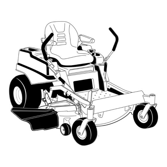
Product Overview G010281 Figure 3 1. Motion control levers 4. Fuel gauge 7. Anti-scalp roller 10. Control panel 2. Operator seat 5. Footrest 8. Deflector 3. Parking brake 6. Front caster wheel 9. Foot pedal deck lift and height-of-cut G010282 Figure 4 1. -
Page 13: Controls
Controls Become familiar with all the controls before you start the engine and operate the machine (Figure 5). G010016 G009918 Figure 5 1. Throttle and choke control 4. Blade control switch (PTO) 2. Hour meter 5. Fuses G010077 Figure 6 3. -
Page 14: Operation
Contact your Authorized Service Dealer or Distributor or go to www.Toro.com for a list of all approved attachments Think Safety First and accessories. Please carefully read all of the safety instructions and decals in the safety section. -
Page 15: Adding Fuel
In certain conditions, gasoline is extremely flammable and highly explosive. A fire or explosion from gasoline can burn you and others and can damage property. • Fill the fuel tank outdoors, in an open area, when the engine is cold. Wipe up any gasoline that spills. - Page 16 Important: Do not use fuel additives containing methanol or ethanol. In certain conditions during fueling, static Add the correct amount of gas stabilizer/conditioner electricity can be released causing a spark to the gas. which can ignite the gasoline vapors. A fire Note: A fuel stabilizer/conditioner is most effective or explosion from gasoline can burn you and when mixed with fresh gasoline.
-
Page 17: Checking The Engine Oil Level
Releasing the Parking Brake G010016 G010079 Figure 11 Operating the Throttle The throttle control can be moved between Fast and Slow positions (Figure 12). Always use the fast position when turning on the mower deck with the blade control switch (PTO). G010475 G010289 Figure 9... -
Page 18: Operating The Ignition Switch
Operating the Ignition Switch 1. Turn the ignition key to the Start position (Figure 14). When the engines starts, release the key. Important: Do not engage starter for more than 5 seconds at a time. If the engine fails to start allow a 15 second cool-down period between attempts. -
Page 19: Operating The Mower Blade Control Switch (Pto)
Stopping the Engine Children or bystanders may be injured if they move or attempt to operate the tractor while it is unattended. G008945 Figure 18 Always remove the ignition key and set the parking brake when leaving the machine unattended, even if just for a few minutes. Disengaging the Blade Control Switch (PTO) G009174... -
Page 20: Driving Forward Or Backward
Testing the Safety Interlock System Using the Motion Control Levers Test the safety interlock system before you use the machine each time. If the safety system does not operate as described below, have an Authorized Service Dealer repair the safety system immediately. 1. -
Page 21: Stopping The Machine
Stopping the Machine To stop the machine, move the traction control levers to neutral and move to locked position, disengage the blade control switch (PTO), and turn the ignition key to off. Set the parking brake when you leave the machine; refer to Setting the Parking Brake. -
Page 22: Adjusting The Anti-Scalp Rollers
G010016 G010236 Figure 24 1. Deck lift pedal 4. Lock position. lowest height-of-cut (use only for deck removal) 2. Cut height pin 5. Lock position. transport position 3. Height-of-cut positions Using the Lock Positions G010219 The deck can be locked in the highest height-of-cut or Figure 23 transport position or the lowest height-of-cut position. -
Page 23: Positioning The Seat
Changing the Seat Ride Suspension The number of seat springs can be changed to maximize rider comfort. More springs should be used G010233 with heavier operators and on rough terrain. Fewer springs should be used with lighter operators and when mowing smooth, well established lawns. -
Page 24: Pushing The Machine By Hand
Pushing the Machine by Hand Important: Always push the machine by hand. Never tow the machine because damage may occur. To Push the Machine 1. Park the machine on a level surface and disengage the blade control switch. 2. Move the motion control levers outward to neutral lock position, stop the engine, remove the key, and wait for all moving parts to stop before leaving the operating position. -
Page 25: Using The Side Discharge
To Operate the Machine than six inches tall, you may want to cut the lawn twice to ensure an acceptable quality of cut. Move the bypass to the position for pushing the machine (Figure 30) to engage the wheel motors. Cut 1/3 of the Grass Blade Using the Side Discharge It is best to cut only about 1/3 of the grass blade. - Page 26 Check the cutter blades daily for sharpness, and for any wear or damage. File down any nicks and sharpen the blades as necessary. If a blade is damaged or worn, replace it immediately with a genuine TORO replacement blade.
-
Page 27: Maintenance
Maintenance Recommended Maintenance Schedule(s) Maintenance Service Maintenance Procedure Interval • Change the engine oil. After the first 8 hours • Change the hydraulic system filter and oil. After the first 50 hours • Check the safety interlock system. • Check the air cleaner for dirty, loose or damaged parts. •... - Page 28 Figure 31 Located on the seat pan underside 1. Read the Operator’s Manual before performing any 4. Check the hydraulic oil every 25 hours maintenance. 2. Check the engine oil every 8 hours 5. Check the caster wheel tire pressure every 25 hours 3.
-
Page 29: Premaintenance Procedures
Premaintenance Lubrication Procedures Greasing the Bearings Raising the Seat Service Interval: Every 25 hours—Grease all lubrication points. Make sure the motion control levers are locked in the Grease Type: No. 2 General Purpose Lithium Base neutral lock position. Lift the seat forward. Grease The following components can be accessed by raising 1. -
Page 30: Engine Maintenance
Engine Maintenance G010345 Contact with hot surfaces may cause personal injury. Keep hands, feet, face, clothing and other body parts away the muffler and other hot surfaces. Servicing the Air Cleaner Service Interval: Before each use or daily—Check the air cleaner for dirty, loose or damaged Figure 34 parts. - Page 31 SAE V iscosity Grades 5W 30, 10W 30 G009948 Synthetic 5W 30, 10W 30 °F °C STARTING TEMPERATURE RANGE ANTICIPATED BEFORE NEXT OIL CHANGE G009969 Figure 35 Note: Use of non-synthetic multi-grade oils (5W-30, 10W-30, etc.) in temperatures above 40 degrees F (4 degrees C) will result in higher than normal oil consumption.
- Page 32 4. Stop the engine, remove the key, and wait for all 5. Slowly pour approximately 80% of the specified oil moving parts to stop before leaving the operating into the filler tube and slowly add the additional oil position (Figure 37). to bring it to the Full mark (Figure 38).
-
Page 33: Servicing The Spark Plug
Servicing the Spark Plug Service Interval: Every 100 hours (replace them as necessary) G009950 Make sure the air gap between the center and side electrodes is correct before installing the spark plug. Use a spark plug wrench for removing and installing the spark plug(s) and a gapping tool/feeler gauge to check and adjust the air gap. -
Page 34: Cleaning The Blower Housing
Fuel System Maintenance Replacing the Fuel Filter Service Interval: Every 500 hours/Yearly (whichever G008794 comes first) (more often under dusty, Figure 41 dirty conditions). 1. Disengage the blade control switch (PTO), move the motion control levers to the neutral lock position, Installing the Spark Plug and set the parking brake. -
Page 35: Electrical System Maintenance
Electrical System Maintenance Servicing the Battery Service Interval: Monthly Warning CALIFORNIA Proposition 65 Warning Battery posts, terminals, and related accessories contain lead and lead compounds, G008963 chemicals known to the State of California Figure 43 to cause cancer and reproductive harm. 1. - Page 36 5. Slide the red terminal boot off the positive (red) battery terminal and remove the positive (+)(red) battery cable (Figure 44). Incorrect battery cable routing could damage the machine and cables causing sparks. Sparks 6. Remove the clamp (Figure 44). can cause the battery gasses to explode, 7.
-
Page 37: Servicing The Fuses
G010340 Figure 45 1. Positive Battery Post 3. Red (+) Charger Lead 2. Negative Battery Post 4. Black (-) Charger Lead Servicing the Fuses The electrical system is protected by fuses. It requires G010241 no maintenance, however, if a fuse blows check the Figure 46 component/circuit for a malfunction or short. -
Page 38: Drive System Maintenance
Drive System Hydraulic System Maintenance Maintenance Oil Type: 20w-50 engine oil. Checking the Tire Pressure Important: Use oil specified or equivalent. Other fluids could cause system damage. Service Interval: Every 25 hours—Check tire pressure. Maintain the air pressure in the front and rear tires as Checking the Hydraulic Oil specified. - Page 39 result in irreparable damage to the transaxle drive system. Removing Hydraulic System Filters 1. Stop engine, wait for all moving parts to stop, and allow engine to cool. Remove the key and engage the parking brake. 2. Locate the filter and guards on each transaxle drive system (Figure 49).
-
Page 40: Mower Deck Maintenance
File down any nicks and sharpen the blades as necessary. If a blade is damaged or worn, replace it immediately with a genuine Toro replacement 2. Start engine and move throttle control ahead to 1/2 blade. For convenient sharpening and replacement, you throttle position. - Page 41 3. Measure from the tip of the blade to the flat surface here. Figure 52 1. Cutting Edge 3. Wear/slot Forming G009680 2. Curved Area 4. Crack Figure 54 Checking for Bent Blades 1. Blade, in position for measuring 2. Level surface Note: The machine must be on a level surface for the 3.
- Page 42 The blade retains its balance if the same amount of 1/8 inch (3mm), the blade spindle could be bent. material is removed from both cutting edges. Contact an Authorized Toro Dealer for service. B. If the variance is within constraints, move to the next blade..
-
Page 43: Mower Deck Leveling
are not within 3/16 inch (5 mm), an adjustment is required; continue to the Leveling procedure. G005278 Figure 59 1. Blade 2. Balancer Installing the Blades 1. Install the blade onto the spindle shaft (Figure 57). Important: The curved part of the blade must be pointing upward toward the inside of the mower to ensure proper cutting. -
Page 44: Inspecting The Belts
then tighten the four leveling adjust locking nuts (Figure 63). G009659 Figure 61 1. Blades front to rear 3. Measure from the tip of the blade to the flat surface here 2. Outside cutting edges G010312 Leveling the Mower Deck 1. -
Page 45: Removing The Mower
3. Lower the mower to the 3 inch (76 mm) height of 4. Remove the mower belt from the engine pulley; refer cut. to the Replacing the Mower Belt procedure 4. Remove the belt covers over the outside spindles. 5. Lower the height-of-cut lever to the lowest position. 5. -
Page 46: Installing The Mower
An uncovered discharge opening could allow the lawn mower to throw objects in the operator’s or bystander’s direction and result in serious injury. Also, contact with the blade could occur. Never operate the machine without grass deflector, discharge cover or grass collection system in place. -
Page 47: Cleaning
Cleaning Important: The grass deflector must be spring loaded in the down position. Lift the deflector up to test that it snaps to the full down position. Washing the Underside of the Mower Service Interval: Before each use or daily—Clean the mower housing. -
Page 48: Waste Disposal
Storage Note: If the mower is not clean after one washing, soak it and let it stand for 30 minutes. Then repeat the process. Cleaning and Storage 8. Run the mower again for one to three minutes to 1. Disengage the blade control switch (PTO), set the remove excess water. - Page 49 B. Run the engine to distribute conditioned fuel through the fuel system (5 minutes). C. Stop the engine, allow it to cool, and drain the fuel tank; refer to Servicing the Fuel Tank in the Maintenance Section. D. Restart the engine and run it until it stops. E.
-
Page 50: Troubleshooting
Troubleshooting Problem Possible Cause Corrective Action Starter does not crank 1. Blade control switch (PTO) is engaged. 1. Move blade control switch (PTO) to disengaged. 2. Parking brake is not on. 2. Set the parking brake. 3. Drive levers are not in neutral lock 3. - Page 51 Problem Possible Cause Corrective Action Machine does not drive. 1. By pass valves is not closed tight. 1. Tighten the by pass valves. 2. Pump belt is worn, loose or broken. 2. Change the belt. 3. Pump belt is off a pulley. 3.
-
Page 52: Schematics
Schematics G010474 Wire Diagram (Rev. A) - Page 53 Notes:...
- Page 54 Notes:...
- Page 55 Notes:...
- Page 56 Countries Other than the United States or Canada Customers who have purchased Toro products exported from the United States or Canada should contact their Toro Distributor (Dealer) to obtain guarantee policies for your country, province, or state. If for any reason you are dissatisfied with your Distributor’s service or have difficulty obtaining guarantee information, contact the Toro importer.