
Related Manuals for Samsung AN19LS


Summary of Contents for Samsung AN19LS
-
Page 1: Table Of Contents
Manual COLOR MONITOR CONTENTS 1. Precautions 2. Product Specifications 3. Disassembly & Reassembly 4. Alignment & Adjustments 5. Troubleshooting 6. Exploded View & Parts List AN19LS/AN19JS 7. Electrical Parts List 8. Block Diagram 9. Wiring Diagram 10. Schematic Diagrams AN19LT/AN19JT... - Page 2 Samsung Electronics Co.,Ltd. 416, Maetan-3Dong, Paldal-Gu, Suwon City, Kyungki-Do, Korea. Printed in Korea 442-742 P/N : BH82-00005A-00 http://www.samsungmonitor.com (SyncMaster Worldwide) http://www.samsung-monitor.com (SyncMaster USA) http://www.sec.co.kr/monitor (Korea)
-
Page 3: Precautions
CONFIDENTIAL 1 Precautio 1-1 Safety Precautions WARNINGS Leakage Current Hot Check (Figure 1-1): For continued safety, do not attempt to modify the WARNING: Do not use an isolation transformer during circuit board. this test. Use a leakage current tester or a metering system Disconnect the AC power before servicing. - Page 4 CONFIDENTIAL 1 Precautions 1-2 Servicing Precautions WARNING 1:First read the “Safety Precautions” section of this manual. If unforeseen circumstances create conflict between the servicing precautions and safety precautions, always follow the safety precautions. WARNING 2:A high voltage adjusted to the wrong value may cause excessive X-ray emissions. WARNING 3:An electrolytic capacitor installed with the wrong polarity might explode.
-
Page 5: Product Specifications
110 Watt (max) Dimensions (W x D x H) Unit/Gross AN19LS 17.3 x 17.9 x 18.1 Inches (440 x 454 x 460 mm) / 22.3 x 22.8 x 21.3 Inches (566x 580 x 540 mm) AN19LT 17.3 x 17.9 x 17.9 Inches (440 x 454 x 455 mm) / 22.3 x 22.4 x 21.3 Inches (566x 570 x 540 mm) AN19JS 17.3 x 18.1 x 18.1 Inches (440 x 460 x 460 mm) / 22.0 x 25.0 x 21.3 Inches (560x 635 x 540 mm) - Page 6 CONFIDENTIAL 2 Product Specifications 2-2 Pin Assignments Sync Type Macintosh Separate Pin No. GND-R Green Blue H/V Sync. Sense 0 GND (DDC) Green GND-R GND-G GND-G Sense 1 GND-B Reserved Blue GND-Sync./Self-raster Sense 2 DDC Data V-Sync. H-Sync. GND-B V-Sync. DDC Clock H-Sync.
- Page 7 CONFIDENTIAL 2 Product Specifications 2-3 Timing Chart This section of the service manual describes the timing that the computer industry recognizes as standard for computer-generated video signals. Table 2-1 Timing Chart Mode VESA VGA2/70 Hz VGA3/60 Hz 640/85 Hz 640/75 Hz 1280/75 Hz 800/85 Hz 1024/75 Hz...
- Page 8 CONFIDENTIAL 2 Product Specifications Memo AN19L*/AN19J*...
-
Page 9: Disassembly & Reassembly
CONFIDENTIAL 3 Disassembly and Reassembly This section of the service manual describes the disassembly and reassembly procedures for the AN19L*/AN19J* monitor. WARNING: This monitor contains electrostatically sensitive devices. Use with caution when handling these components. 3-1 Disassembly Cautions:1. Disconnect the monitor from the power source before disassembly. 2. - Page 10 CONFIDENTIAL 3 Disassembly and Reassembly 6. Remove the Shield.(TCO 95) 3-1-4 Removing the Main PCB 1. Complete all previous steps. 2. Disconnect the Degaussing Coil at CN603 on the Main PCB. 3. Disconnect all easily accessible ground wires on the PCB and Bottom Chassis. 4.
-
Page 11: Alignment & Adjustments
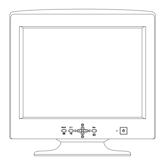
CONFIDENTIAL 4 Alignment and Adjustments This section of the service manual explains how to make permanent adjustments to the monitor. Directions are given for adjustments using the monitor Interface Board Ver. 2.0 and software (Softjig). 4-1 Adjustment Conditions Caution: Changes made without the Softjig are saved only to the user mode settings. As such, the settings are not permanently stored and may be inadvertently deleted by the user. - Page 12 CONFIDENTIAL 4 Alignment and Adjustments 4-2 Display Control Adjustments 4-2-1 HIGH VOLTAGE 4-2-4 Centering Centering means to position the center point of Signal: 1024 x 768 (68 kHz/85 Hz) the display in the middle of the display area. Display image: Don’t care Horizontal size and position and vertical size and Contrast: Minimum...
- Page 13 CONFIDENTIAL 4 Alignment and Adjustments 4-2-4 (c) HORIZONTAL POSITION ADJUSTMENT 4-2-5 (a) HORIZONTAL LINEARITY ADJUSTMENT CONDITIONS CONDITIONS Scanning frequency: 68 kHz/85 Hz Scanning frequency: 68 kHz/85 Hz Display image: Crosshatch pattern Display image: Crosshatch pattern Brightness: Maximum Use control bar after selecting “H-POSITION” in Contrast: Maximum left menu to center the horizontal image on the...
- Page 14 CONFIDENTIAL 4 Alignment and Adjustments 4-2-6 Trapezoid Adjustment 4-2-9 Side Pincushion Adjustment CONDITIONS CONDITIONS Scanning frequency: 68 kHz/85 Hz Scanning frequency: 68 kHz/85 Hz Display image: Crosshatch pattern Display image: Crosshatch pattern Brightness: Maximum Contrast: Maximum Use control bar after selecting “PINCUSHION” in left menu to straighten the sides of the image area.
- Page 15 2. Adjust the luminance of the back raster to adjust the luminance to between 0.5 to 0.7 ft-L using control bar after 65ft -L (± 5ft-L) : AN19LS/AN19JS selecting “GREEN CUTOFF” in the menu. 3. Select “@0: BM OFF” in right menu.
- Page 16 CONFIDENTIAL 4 Alignment and Adjustments 4-3-2 (d) ABL ADJUSTMENT 4. Select “@7: 5-ft “ in right menu. 5. Check whether the white coordinates of the CONDITIONS video meet the above coordinates spec. Scanning frequency: 68 kHz/85 Hz 6. Select “@8: 24-ft “ in right menu. Display image: Full white pattern Brightness:...
- Page 17 CONFIDENTIAL 4 Alignment and Adjustments 4-3-4 Focus Adjustment CONDITIONS Scanning frequency: 68 kHz/85 Hz (1024 x 768) Display image: “H” character pattern Brightness: Cut off point Contrast: Maximum PROCEDURE 1. Adjust the Focus VR on the FBT to display the sharpest image possible.
- Page 18 CONFIDENTIAL 4 Alignment and Adjustments Memo AN19L*/AN19J*...
-
Page 19: Troubleshooting
CONFIDENTIAL 5 Troubleshooting 5-1 Parts Level Troubleshooting Notes: 1. If a picture does not appear, fully rotate the brightness and contrast controls clockwise and reinspect. 2. Check the following circuits. • No raster appears: Power circuit, Horizontal output circuit. • High voltage develops but no raster appears: Video output circuits. •... - Page 20 CONFIDENTIAL 5 Troubleshooting 5-1-2 DPMS Failure WAVEFORMS Check signal source H/V sync. video level. 100 V (IC601, #1) Make No H/V sync. (power off mode) CH1 P-P = 100 V CH1 RMS = 325.8 V LED blinks? Check IC201 Pin 40. +12 V line off? Check IC201 Pin 5.
- Page 21 CONFIDENTIAL 5 Troubleshooting 5-1-3 H_Deflection Failure Does PWM output signal appear Does DC 12V appear at Check 12 V line. at Pin 1 (H_out) of IC401? Pin 29 of IC401? WAVEFORMS Check IC401. 2.00 V (IC401, #1) Does Horizontal pulse signal Check IC401.
- Page 22 CONFIDENTIAL 5 Troubleshooting 5-1-5 Invariable H_Size IC401 Pin 24 voltage varies with Check and replace IC401. different EW_Out DAC values? Q402 Gate output duty varies with Check some parts around different BPOUT valus? Q402 and IC401 Pin 24, 26, 28. 5-1-6 Abnormal H_Size IC401 Pin 24 output duty WAVEFORMS...
- Page 23 CONFIDENTIAL 5 Troubleshooting 5-1-7 Side Pin or Trap Failure WAVEFORMS IC401 Pin 24 output exists? Check and replace IC401. 1.00 V (IC401, #24) Refer to 5-1-6 Abnormal H_Size . CH1 P-P = 1.00V CH1 RMS = 3.008 V 5-1-8 Para. or Pin Balance Failure IC401 Pin 24 output varies with Refer to 5-1-6 Abnormal H_Size .
- Page 24 CONFIDENTIAL 5 Troubleshooting 5-1-10 V Deflection Failure WAVEFORMS 13 V, –10 V line is on? Refer to 5-1-1 No Power Supply 500 V (IC401, #2) IC401 Pin 2 output exists? Check and replace IC401. CH1 P-P = 500 V CH1 RMS = 1.425 V Check and replace components IC301 Pin 6 output exists? around IC301.
- Page 25 CONFIDENTIAL 5 Troubleshooting 5-1-12 High Voltage Failure WAVEFORMS Check and replace IC401 Pin 28 BPOUT pulse exists? IC401 and +12 V line. 2.00 V (IC401, #28) Q402 Gate driving pulse exists? Check and replace Q401, Q423. CH1 P-P = 2.00V CH1 RMS = 5.868V Check and replace Q403, Q402 Drain pulse exists?
- Page 26 CONFIDENTIAL 5 Troubleshooting 5-1-14 No Video WAVEFORMS Check signal cable and connection. 1.00 V (IC102,#5, 8, 10) IC102 Pin 5, 8 and 10 Check the signal cable connection. inputs are right? IC102 Pin 23, 26 and 28 Check I C bus and +12 V line. outputs are right? 1.00 V (IC102, #23,26,28) IC105 Pin 6, 7 and 9...
- Page 27 CONFIDENTIAL 5 Troubleshooting 5-1-15 No Highlight Zone (AN19JS/AN19LS) WAVEFORMS 1.00 V (IC101, #18, 20, 22) IC101 Pin 2, 4 and 6 inputs are right? IC101 Pin 18, 20 and 22 Check +5V IC101 pin 1, 11. outputs are right? 1.00 V (IC101, #14)
- Page 28 CONFIDENTIAL 5 Troubleshooting 5-1-17 OSD Failure WAVEFORMS IC103 Pin 5, 24 input is 5V? Check +5V Line. 1.00 V (IC103, #5, 24) Check IC103 Pin 7, 8 I Check I C wavefroms. Data / Clock Line? CH1 P-P = 1.00V CH1 RMS = 4.516V IC103 Pin 6 and 17 Check H-FLB 2, V_BLK.
- Page 29 CONFIDENTIAL 5 Troubleshooting 5-1-18 User Control Failure Does the DC level change at Pin 36, 37 of IC201 when you Check the of key function button . push the S/W button? Check IC201, CN203. 5-1-19 Degaussing Failure Check degaussing connector CN603. RL601 operation is right? Check D-coil and TH601.
- Page 30 CONFIDENTIAL 5 Troubleshooting 5-2 General Troubleshooting 5-2-1 No Picture LED blinks? Refer to 5-2-2 Shut down. LED is green color? Check Micom. Check G2 voltage, high voltage and R, G, B cathode voltage. 5-2-2 Shut Down Blinking LED’s? Check power supply. Check horizontal, vertical deflection Scan failure? system and check power...
- Page 31 CONFIDENTIAL 5 Troubleshooting 5-2-3 Missing Color WAVEFORMS 10.0 V (R,G,B, Video) Proper Video levels are Check signal generator. on CN101 (D-Sub) Pin 1, 3 and 5? Proper Video signal Refer to 5-1-14 No Video. to all cathodes? CH1 P-P = 10.0V CH1 RMS = 17.02V Check IC101 Pin 18, 20 and 22.
- Page 32 CONFIDENTIAL 5 Troubleshooting 5-2-4 Visible Retrace WAVEFORMS Check white balance adjustment. 5.00V (Q303, Collector) G2 voltage is right? Check D500, D502, Adjust G2. Blank pulse at Pin 17 of IC401? Check IC401. CH1 P-P = 5.00V CH1 RMS = 28.33V 20.00V (CRT Socket, G1) V_FLB pulse at Check Blank pulse at...
- Page 33 CONFIDENTIAL 5 Troubleshooting 5-2-5 Unsynchronized Image Check input signals Pin 2 and 3 of CN202. Signals are right? Check Video Cable. Signals at Pin 28 and 29 of Check IC201. IC201 are right? Signals at Pin 1 and 2 of Check IC401.
- Page 34 CONFIDENTIAL 5 Troubleshooting 5-2-6 Misconvergence Adjust convergence. Convergence is Done now within spec.? Readjust convergence. Convergence is Done now within spec.? Change CRT and readjust convergence. Done 5-16 AN19L*/AN19J*...
- Page 35 CONFIDENTIAL 5 Troubleshooting 5-2-7 Poor Focus Adjust focus VR of FBT. Align monitor and check for focus Improved focus? change. Check focus leads from FBT to CRT Socket. Check CRT Socket. Replace the CRT and verify focus. 5-2-8 Purity Failure Degause Purity is correct? Done...
- Page 36 CONFIDENTIAL 5 Troubleshooting Memo 5-18 AN19L*/AN19J*...
-
Page 41: Electrical Parts List
7 Electrical Parts List 7-1-1 AN19L* Main PCB Parts Loc. No. Code No. Description Specification Remarks BH94-00821A ASSY PCB MAIN AN19LS AN_LABEL BH68-00446D LABEL AN-STICKER,ART-PAPER 100G,15,15,BLACK,YELLOW C409 2306-000147 C-FILM,MPPF 1uF,5%,250V,BK,26x24x15,22.5mm C430 2306-000263 C-FILM,MPPF 770nF,5%,250V,BK,26x21.5x13.5, C431 2306-000127 C-FILM,MPPF 120nF,5%,400V,TP,21.5x17mm,5mm C601 2301-001195 C-FILM,MPPF 150nF,10%,275VAC,BK,26x16.5x7,... - Page 42 BH26-00090B TRANS HORIZ.DRIVE EI-1916,AN19J,7P,35.0MH,185TS/13TS/95TS,73.0UH,7.5/0.05OHM,PL3,EI-1916,170UH MAX T501 BH26-00150A TRANS FBT FQM19A007,AN19L,1.13MH,SM-19C,FUR3657,137V,14P,-10 ~60,BK,27KV T502 BH26-00120A TRANS-FOCUS EE1916,PN17L(TOSHIBA),5P,1.7MH MIN,-,-,112MH MIN,-,-,0.85OHM/15OHM MAX,-,PL3,EE1 T601 BH26-00146A TRANS SWITCHING EER3541,AN19LS,90 ~264,PL3,PM2A,EER3541,320UH,102UH T602 BH26-00141A TRANS-SYNC AR0615(L-81),AN17L,5P,200UH,200UH,1.30 OHM,L-81,AR0630, BAR,18*13*18.5,BK TH601 1404-001264 THERMISTOR-PTC 4.5OHM,+30/-20%,220V,290VAC,21A,-,TR TH602 1404-001020 THERMISTOR-NTC 8ohm,15%,-,17mW/C,BK VR401 2103-001049...
- Page 43 7 Electrical Parts List Loc. No. Code No. Description Specification Remarks C312 2401-001016 C-AL 3.3UF,20%,50V,BP,TP,5X11,5 C313 2301-000010 C-FILM,PEF 100nF,5%,100V,TP,11.5x12.5mm,5 C406 2301-000004 C-FILM,PEF 2.2nF,5%,100V,TP,5.5X10X2.9,5m C407 2401-000887 C-AL 220uF,20%,63V,GP,TP,10x20,5 C408 2201-000110 C-CERAMIC,DISC 1.5nF,10%,500V,Y5P,TP,8.5x3,5 C410 2401-000050 C-AL 10uF,20%,16V,GP,TP,5x11,2.5 C411 2301-000180 C-FILM,PEF 18nF,0.05,100V,TP,7.2x4.5x8.0m C412 2301-000519 C-FILM,PEF 3.3nF,5%,100V,TP,5.8x3x12.5,5m...
- Page 44 7 Electrical Parts List Loc. No. Code No. Description Specification Remarks C551 2401-000913 C-AL 22uF,20%,16V,GP,TP,5x11,5 C552 2201-000132 C-CERAMIC,DISC 0.1nF,10%,500V,Y5P,TP,6.5x3,5 C603 2201-000023 C-CERAMIC,DISC 2.2nF,20%,125V,Y5U,TP,11x7,5 C604 2201-000023 C-CERAMIC,DISC 2.2nF,20%,125V,Y5U,TP,11x7,5 C607 2202-002009 C-CERAMIC,MLC-AXIAL 100nF,+80-20%,50V,Y5V,TP,2.3X3 C609 2401-000966 C-AL 22uF,20%,50V,GP,TP,5x11,5 C610 2202-000252 C-CERAMIC,MLC-AXIAL 4.7nF,10%,50V,X7R,TP,2.5x4.3,- C611 2401-000613 C-AL 1uF,20%,50V,WT,TP,5x11,5...
- Page 45 7 Electrical Parts List Loc. No. Code No. Description Specification Remarks D500 0402-000252 DIODE-RECTIFIER RGP02-16E,1.6KV,0.5A,DO-41,TP D501 0401-000005 DIODE-SWITCHING 1N4148,100V,200mA,DO-35,TP D502 0402-000252 DIODE-RECTIFIER RGP02-16E,1.6KV,0.5A,DO-41,TP D504 0402-000017 DIODE-RECTIFIER RGP02-12,1200V,0.5A,DO-204AL,T D509 0401-000005 DIODE-SWITCHING 1N4148,100V,200mA,DO-35,TP D511 0401-000005 DIODE-SWITCHING 1N4148,100V,200mA,DO-35,TP D512 0401-000005 DIODE-SWITCHING 1N4148,100V,200mA,DO-35,TP D515 0401-000005 DIODE-SWITCHING 1N4148,100V,200mA,DO-35,TP...
- Page 46 7 Electrical Parts List Loc. No. Code No. Description Specification Remarks EY609 6042-000002 EYELET ID1.5,OD2,L3.1,SN,BSS3-E/EH EY610 6042-000002 EYELET ID1.5,OD2,L3.1,SN,BSS3-E/EH GT603 BH71-40300A PIN HINGE BRASS,D2.36!,HEAT/SINK,SN GT604 BH71-40300A PIN HINGE BRASS,D2.36!,HEAT/SINK,SN IC202 1103-001150 IC-EEPROM 524C80D81,8KBit,DIP,8P,300MIL,10mS,5V,10%,PLASTIC,-25to+70C,10uA,CMOS,ST IC603 1203-002653 IC-POSI.FIXED REG. 78DL05,TO-92,3P,4.5X4.5MM,PLASTIC,4.8/5.2V,625MW,-40TO+85C,150MA,-,TP IC605 1203-000002 IC-POSI.ADJUST REG.
- Page 47 7 Electrical Parts List Loc. No. Code No. Description Specification Remarks JP35 BH39-40305U CBF HARNESS 52MM,AWG22(0.6PI),-,-,AWG22(0. JP36 BH39-40305U CBF HARNESS 52MM,AWG22(0.6PI),-,-,AWG22(0. JP37 BH39-40305U CBF HARNESS 52MM,AWG22(0.6PI),-,-,AWG22(0. JP38 BH39-40305U CBF HARNESS 52MM,AWG22(0.6PI),-,-,AWG22(0. BH39-40305U CBF HARNESS 52MM,AWG22(0.6PI),-,-,AWG22(0. JP40 BH39-40305U CBF HARNESS 52MM,AWG22(0.6PI),-,-,AWG22(0. JP41 BH39-40305U CBF HARNESS...
- Page 48 7 Electrical Parts List Loc. No. Code No. Description Specification Remarks Q407 0501-000140 TR-SMALL SIGNAL 2N5551,NPN,625mW,TO-92,TP,80-250 Q420 0501-000586 TR-SMALL SIGNAL KSC945,NPN,250mW,TO-92,TP,120-240 Q423 0501-000303 TR-SMALL SIGNAL KSA733,PNP,250mW,TO-92,TP,120-240 Q501 0501-000586 TR-SMALL SIGNAL KSC945,NPN,250mW,TO-92,TP,120-240 Q502 0501-000143 TR-SMALL SIGNAL 2N6520,PNP,625mW,TO-92,TP,30-200 Q503 0501-000122 TR-SMALL SIGNAL 2N3904,NPN,625mW,TO-92,TP,100-300 Q504 0501-000122...
- Page 49 7 Electrical Parts List Loc. No. Code No. Description Specification Remarks R307 2001-000016 R-CARBON(S) 1OHM,5%,1/2W,AA,TP,2.4X6.4MM R308 2001-000109 R-CARBON(S) 470OHM,5%,1/2W,AA,TP,2.4X6.4MM R309 2004-004981 R-METAL 3ohm,2%,1/4W,AA,TP,2.4x6.4mm R310 2004-001226 R-METAL 750ohm,1%,1/4W,AA,TP,2.4x6.4mm R311 2004-001661 R-METAL 3Kohm,1%,1/4W,AA,TP,2.4x6.4mm R312 2004-001023 R-METAL 5.6Kohm,1%,1/8W,AA,TP,1.8x3.2m R315 2004-001409 R-METAL 2.7ohm,1%,1/4W,AA,TP,2.4x6.4mm R320 2001-000313 R-CARBON 11KOHM,5%,1/8W,AA,TP,1.8X3.2MM...
- Page 50 7 Electrical Parts List Loc. No. Code No. Description Specification Remarks R463 2001-000273 R-CARBON 100KOHM,5%,1/8W,AA,TP,1.8X3.2MM R464 2001-000010 R-CARBON 68KOHM,5%,1/8W,AA,TP,1.8X3.2MM R465 2001-000273 R-CARBON 100KOHM,5%,1/8W,AA,TP,1.8X3.2MM R466 2001-000010 R-CARBON 68KOHM,5%,1/8W,AA,TP,1.8X3.2MM R500 2001-000478 R-CARBON 2.7OHM,5%,1/4W,AA,TP,2.4X6.4MM R501 2001-000864 R-CARBON 56KOHM,5%,1/8W,AA,TP,1.8X3.2MM R502 2004-000781 R-METAL 330Kohm,1%,1/4W,AA,TP,2.4x6.4m R503 2004-000796 R-METAL 33Kohm,1%,1/4W,AA,TP,2.4x6.4mm...
- Page 51 7 Electrical Parts List Loc. No. Code No. Description Specification Remarks R613 2001-000290 R-CARBON 10KOHM,5%,1/8W,AA,TP,1.8X3.2MM R614 2001-000037 R-CARBON(S) 330OHM,5%,1/2W,AA,TP,2.4X6.4MM R615_1 2001-001117 R-CARBON(S) 2KOHM,5%,1/2W,AA,TP,2.4X6.4MM R615_2 2001-001117 R-CARBON(S) 2KOHM,5%,1/2W,AA,TP,2.4X6.4MM R616 2001-001108 R-CARBON(S) 22KOHM,5%,1/2W,AA,TP,2.4X6.4MM R618 2001-000429 R-CARBON 1KOHM,5%,1/8W,AA,TP,1.8X3.2MM R620 2001-000354 R-CARBON 150KOHM,5%,1/4W,AA,TP,2.4X6.4MM R630 2001-000786 R-CARBON 47KOHM,5%,1/8W,AA,TP,1.8X3.2MM...
- Page 52 7 Electrical Parts List Loc. No. Code No. Description Specification Remarks 0202-001044 SOLDER-WIRE. S63S-W3.0,S63S,D3,63Sn/37Pb,- 0402-001191 DIODE-RECTIFIER MUR460,600V,4A,CASE267-03,BK BH62-30024B HEAT SINK-IC SPC-1,T1,SN COATING,- HS401 BP96-00067B ASSY HEAT SINK P H/S TR,SCREW+NUT,IRF640B,OIL SILICON 0205-001027 OIL-SILICON G746,-,- 0505-000131 FET-SILICON IRF640,N,200V,18A,0.18ohm,125W 6006-001008 SCREW-ASS’Y MACH WSP,BH,+,M3,L10,ZPC(YEL),SWRCH 6021-000118 NUT-HEXAGON...
- Page 53 7 Electrical Parts List 7-1-2 AN19L* Video PCB Parts Loc. No. Code No. Description Specification Remarks BH94-00830A ASSY PCB VIDEO AN19JS BH62-00033A HEAT SINK-VIDEO PN17MT,A6063S,T1.0,W24,L50,-,-,- CIS1 0202-001044 SOLDER-WIRE. S63S-W3.0,S63S,D3,63Sn/37Pb,- CIS2 0202-001046 SOLDER-WIRE FLUX CF-110VH-2A,-,-,-,- CIS3 0202-001222 SOLDER-WIRE FLUX RS-107,RS60-1.2AA,D1.2,SN60/PB40,- CIS4 0204-001095 THINNER #4520,-,-,-...
- Page 54 7 Electrical Parts List Loc. No. Code No. Description Specification Remarks L111 2703-001334 INDUCTOR-SMD 1.5uH,10%,2x1.25x0.85mm R101 2007-001071 R-CHIP 6.8KOHM,5%,1/10W,DA,TP,2012 R102 2007-000355 R-CHIP 12KOHM,5%,1/10W,DA,TP,2012 R103 2007-001071 R-CHIP 6.8KOHM,5%,1/10W,DA,TP,2012 R105 2007-000766 R-CHIP 330OHM,5%,1/10W,DA,TP,2012 R106 2007-000781 R-CHIP 33OHM,5%,1/10W,DA,TP,2012 R107 2007-000290 R-CHIP 100OHM,5%,1/10W,DA,TP,2012 R108 2007-000290 R-CHIP 100OHM,5%,1/10W,DA,TP,2012...
- Page 55 7 Electrical Parts List Loc. No. Code No. Description Specification Remarks BD103 3301-000011 CORE-FERRITE BEAD AA,3.5x1.0x5.7mm,1500,2375G BD104 3301-000011 CORE-FERRITE BEAD AA,3.5x1.0x5.7mm,1500,2375G BD106 3301-000011 CORE-FERRITE BEAD AA,3.5x1.0x5.7mm,1500,2375G BD112 3301-000011 CORE-FERRITE BEAD AA,3.5x1.0x5.7mm,1500,2375G BD115 3301-000011 CORE-FERRITE BEAD AA,3.5x1.0x5.7mm,1500,2375G C102 2201-000119 C-CERAMIC,DISC 100nF,+80-20%,50V,Y5V,TP,8x3,5 C104 2401-003224 C-AL...
- Page 56 7 Electrical Parts List Loc. No. Code No. Description Specification Remarks IC104 BH13-00022A IC HYBRID-BIAS CLAMP LM2480NA,PN15H/17L,8P,0to+70C,DIP,3mA,85V,ST IC106 1203-002653 IC-POSI.FIXED REG. 78DL05,TO-92,3P,4.5X4.5MM,PLASTIC,4.8/5.2V,625MW,-40TO+85C,150MA,-,TP JP16 BH39-40305U CBF HARNESS 52MM,AWG22(0.6PI),-,-,AWG22(0. JP20 BH39-40305U CBF HARNESS 52MM,AWG22(0.6PI),-,-,AWG22(0. JP21 BH39-40305U CBF HARNESS 52MM,AWG22(0.6PI),-,-,AWG22(0. JP23 BH39-40305U CBF HARNESS 52MM,AWG22(0.6PI),-,-,AWG22(0.
- Page 57 7 Electrical Parts List Loc. No. Code No. Description Specification Remarks R110 2001-000281 R-CARBON 100OHM,5%,1/8W,AA,TP,1.8X3.2MM R115 2001-000022 R-CARBON(S) 33OHM,5%,1/2W,AA,TP,2.4X6.4MM R145H BH39-40305U CBF HARNESS 52MM,AWG22(0.6PI),-,-,AWG22(0. R151 2001-001138 R-CARBON(S) 390OHM,5%,1/2W,AA,TP,2.4X6.4MM RB03 2001-000766 R-CARBON 43KOHM,5%,1/8W,AA,TP,1.8X3.2MM RB08 2001-000938 R-CARBON 68OHM,5%,1/8W,AA,TP,1.8X3.2MM RB09 2001-000643 R-CARBON 330KOHM,5%,1/4W,AA,TP,2.4X6.4MM RB11 2001-001088 R-CARBON(S)
- Page 58 BH72-00093A STAND BASE PG19NS,ABS HB,IV16 BH72-00278A STAND TOP PN19LT,ABS,HB,IV16 BH90-00544A ASSY COVER REAR AN19JS BH72-00349A COVER REAR AQ19JS,ABS,HB,IV16 BH91-00794A ASSY CHASSIS AN19LS BH91-00805A ASSY SHIELD AN19JS SH/BTM+SH/COV 6003-000010 SCREW-TAPTITE BWH,+,B,M3,L10,ZPC(YEL),SWRCH1 BH75-00280B UNIT-SHIELD/COVER PN19LT,-,A1050S H14 T0.3,-,-,-,- BH72-00292A SHEET ABS-ANODE PN19LT,PP,NTR,-,V2,-,-,- BH75-00280A UNIT-SHIELD/COVER PN19LT,-,A1050S H14 T0.3,-,-,-,-...
- Page 59 AQ19HS,EPS M60,-,-,-,-,-,-,- BH69-30002C BAG-PE LDPE,T0.05,W2400,NO_PRINT BH69-30348B BAG-PE HDPE,T0.02,W1120*L1100,Y,-,CGE BH69-30360A BAG-AIR HDPE,T0.2,W1000*L1800,N,-,ALL BH69-40380A PACKING-PAD DW-2,500X2200X200,-,CGK5527 BH92-00865A ASSY BOX AN19LS BH68-00329C LABEL BAR CODE -,ALL,TCO99,DOMESTIC,ART-PAPER 90G,-,WHT,BLACK,-,-,- BH69-00484A S/M955B,W/W,CB-DW3,YEL,A-1,L565*W555*H505 BH92-00866A ASSY LABEL AN19LS LABEL BH68-00497A LABEL RATING AN19JS@ADC,PE,T0.05,109,50,SYNC,PE NATURE BH92-00867A ASSY ACCESSORY AN19LS...
- Page 60 7 Electrical Parts List 7-2-1 AN19J* Main PCB Parts Loc. No. Code No. Description Specification Remarks BH94-00829A ASSY PCB MAIN AN19JS AN_LABEL BH68-00446D LABEL AN-STICKER,ART-PAPER 100G,15,15,BLACK,YELLOW C409 2306-000147 C-FILM,MPPF 1uF,5%,250V,BK,26x24x15,22.5mm C430 2306-000263 C-FILM,MPPF 770nF,5%,250V,BK,26x21.5x13.5, C431 2301-001259 C-FILM,MPPF 100nF,5%,400V,TP,19x8x16,7.5mm C601 2301-001195 C-FILM,MPPF 150nF,10%,275VAC,BK,26x16.5x7, C602...
- Page 61 BH26-00090B TRANS HORIZ.DRIVE EI-1916,AN19J,7P,35.0MH,185TS/13TS/95TS,73.0UH,7.5/0.05OHM,PL3,EI-1916,170UH MAX T501 BH26-00150A TRANS FBT FQM19A007,AN19L,1.13MH,SM-19C,FUR3657,137V,14P,-10 ~60,BK,27KV T502 BH26-00120A TRANS-FOCUS EE1916,PN17L(TOSHIBA),5P,1.7MH MIN,-,-,112MH MIN,-,-,0.85OHM/15OHM MAX,-,PL3,EE1 T601 BH26-00146A TRANS SWITCHING EER3541,AN19LS,90 ~264,PL3,PM2A,EER3541,320UH,102UH T602 BH26-00141A TRANS-SYNC AR0615(L-81),AN17L,5P,200UH,200UH,1.30 OHM,L-81,AR0630, BAR,18*13*18.5,BK TH601 1404-001264 THERMISTOR-PTC 4.5OHM,+30/-20%,220V,290VAC,21A,-,TR TH602 1404-001020 THERMISTOR-NTC 8ohm,15%,-,17mW/C,BK VR401 2103-001049...
- Page 62 7 Electrical Parts List Loc. No. Code No. Description Specification Remarks C406 2301-000004 C-FILM,PEF 2.2nF,5%,100V,TP,5.5X10X2.9,5m C407 2401-000887 C-AL 220uF,20%,63V,GP,TP,10x20,5 C408 2201-000110 C-CERAMIC,DISC 1.5nF,10%,500V,Y5P,TP,8.5x3,5 C410 2401-000050 C-AL 10uF,20%,16V,GP,TP,5x11,2.5 C411 2301-000180 C-FILM,PEF 18nF,0.05,100V,TP,7.2x4.5x8.0m C412 2301-000519 C-FILM,PEF 3.3nF,5%,100V,TP,5.8x3x12.5,5m C413 2401-001012 C-AL 3.3UF,20%,50V,BP,TP,16X25,7.5 C414 2401-001334 C-AL 470nF,20%,50V,GP,TP,5x11,2.5...
- Page 63 7 Electrical Parts List Loc. No. Code No. Description Specification Remarks C603 2201-000023 C-CERAMIC,DISC 2.2nF,20%,125V,Y5U,TP,11x7,5 C604 2201-000023 C-CERAMIC,DISC 2.2nF,20%,125V,Y5U,TP,11x7,5 C607 2202-002009 C-CERAMIC,MLC-AXIAL 100nF,+80-20%,50V,Y5V,TP,2.3X3 C609 2401-000966 C-AL 22uF,20%,50V,GP,TP,5x11,5 C610 2202-000252 C-CERAMIC,MLC-AXIAL 4.7nF,10%,50V,X7R,TP,2.5x4.3,- C611 2401-000613 C-AL 1uF,20%,50V,WT,TP,5x11,5 C612 2401-000613 C-AL 1uF,20%,50V,WT,TP,5x11,5 C613 2201-000012 C-CERAMIC,DISC 0.22nF,10%,1kV,Y5P,TP,6.3x5,5...
- Page 64 7 Electrical Parts List Loc. No. Code No. Description Specification Remarks D502 0402-000252 DIODE-RECTIFIER RGP02-16E,1.6KV,0.5A,DO-41,TP D504 0402-000017 DIODE-RECTIFIER RGP02-12,1200V,0.5A,DO-204AL,T D509 0401-000005 DIODE-SWITCHING 1N4148,100V,200mA,DO-35,TP D511 0401-000005 DIODE-SWITCHING 1N4148,100V,200mA,DO-35,TP D512 0401-000005 DIODE-SWITCHING 1N4148,100V,200mA,DO-35,TP D515 0401-000005 DIODE-SWITCHING 1N4148,100V,200mA,DO-35,TP D516 0401-000005 DIODE-SWITCHING 1N4148,100V,200mA,DO-35,TP D518 0401-000005 DIODE-SWITCHING 1N4148,100V,200mA,DO-35,TP...
- Page 65 7 Electrical Parts List Loc. No. Code No. Description Specification Remarks GT603 BH71-40300A PIN HINGE BRASS,D2.36!,HEAT/SINK,SN GT604 BH71-40300A PIN HINGE BRASS,D2.36!,HEAT/SINK,SN IC202 1103-001150 IC-EEPROM 524C80D81,8KBit,DIP,8P,300MIL,10mS,5V,10%,PLASTIC,-25to+70C,10uA,CMOS,ST IC603 1203-002653 IC-POSI.FIXED REG. 78DL05,TO-92,3P,4.5X4.5MM,PLASTIC,4.8/5.2V,625MW,-40TO+85C,150MA,-,TP IC605 1203-000002 IC-POSI.ADJUST REG. 431,TO-92,3P,-,PLASTIC,2.44/2. BH39-40305U CBF HARNESS 52MM,AWG22(0.6PI),-,-,AWG22(0. JP100 BH39-40305U CBF HARNESS 52MM,AWG22(0.6PI),-,-,AWG22(0.
- Page 66 7 Electrical Parts List Loc. No. Code No. Description Specification Remarks JP37 BH39-40305U CBF HARNESS 52MM,AWG22(0.6PI),-,-,AWG22(0. JP38 BH39-40305U CBF HARNESS 52MM,AWG22(0.6PI),-,-,AWG22(0. BH39-40305U CBF HARNESS 52MM,AWG22(0.6PI),-,-,AWG22(0. JP40 BH39-40305U CBF HARNESS 52MM,AWG22(0.6PI),-,-,AWG22(0. JP41 BH39-40305U CBF HARNESS 52MM,AWG22(0.6PI),-,-,AWG22(0. JP43 BH39-40305U CBF HARNESS 52MM,AWG22(0.6PI),-,-,AWG22(0. JP44 BH39-40305U CBF HARNESS...
- Page 67 7 Electrical Parts List Loc. No. Code No. Description Specification Remarks Q423 0501-000303 TR-SMALL SIGNAL KSA733,PNP,250mW,TO-92,TP,120-240 Q501 0501-000586 TR-SMALL SIGNAL KSC945,NPN,250mW,TO-92,TP,120-240 Q502 0501-000143 TR-SMALL SIGNAL 2N6520,PNP,625mW,TO-92,TP,30-200 Q503 0501-000122 TR-SMALL SIGNAL 2N3904,NPN,625mW,TO-92,TP,100-300 Q504 0501-000122 TR-SMALL SIGNAL 2N3904,NPN,625mW,TO-92,TP,100-300 Q551 0501-000413 TR-SMALL SIGNAL KSP44,NPN,625mW,TO-92,TP,50-200 Q601 0501-000586...
- Page 68 7 Electrical Parts List Loc. No. Code No. Description Specification Remarks R309 2004-004981 R-METAL 3ohm,2%,1/4W,AA,TP,2.4x6.4mm R310 2004-001226 R-METAL 750ohm,1%,1/4W,AA,TP,2.4x6.4mm R311 2004-001661 R-METAL 3Kohm,1%,1/4W,AA,TP,2.4x6.4mm R312 2004-001023 R-METAL 5.6Kohm,1%,1/8W,AA,TP,1.8x3.2m R315 2004-004981 R-METAL 3ohm,2%,1/4W,AA,TP,2.4x6.4mm R320 2001-000313 R-CARBON 11KOHM,5%,1/8W,AA,TP,1.8X3.2MM R321 2001-000947 R-CARBON 7.5KOHM,5%,1/8W,AA,TP,1.8X3.2MM R322 2001-000019 R-CARBON(S) 10OHM,5%,1/2W,AA,TP,2.4X6.4MM...
- Page 69 7 Electrical Parts List Loc. No. Code No. Description Specification Remarks R465 2001-000273 R-CARBON 100KOHM,5%,1/8W,AA,TP,1.8X3.2MM R466 2001-000010 R-CARBON 68KOHM,5%,1/8W,AA,TP,1.8X3.2MM R500 2001-000478 R-CARBON 2.7OHM,5%,1/4W,AA,TP,2.4X6.4MM R501 2001-000864 R-CARBON 56KOHM,5%,1/8W,AA,TP,1.8X3.2MM R502 2004-000781 R-METAL 330Kohm,1%,1/4W,AA,TP,2.4x6.4m R503 2004-000796 R-METAL 33Kohm,1%,1/4W,AA,TP,2.4x6.4mm R504 2001-000522 R-CARBON 22KOHM,5%,1/8W,AA,TP,1.8X3.2MM R505 2001-000290 R-CARBON 10KOHM,5%,1/8W,AA,TP,1.8X3.2MM...
- Page 70 7 Electrical Parts List Loc. No. Code No. Description Specification Remarks R615_1 2001-001117 R-CARBON(S) 2KOHM,5%,1/2W,AA,TP,2.4X6.4MM R615_2 2001-001117 R-CARBON(S) 2KOHM,5%,1/2W,AA,TP,2.4X6.4MM R616 2001-001108 R-CARBON(S) 22KOHM,5%,1/2W,AA,TP,2.4X6.4MM R618 2001-000429 R-CARBON 1KOHM,5%,1/8W,AA,TP,1.8X3.2MM R620 2001-000354 R-CARBON 150KOHM,5%,1/4W,AA,TP,2.4X6.4MM R630 2001-000786 R-CARBON 47KOHM,5%,1/8W,AA,TP,1.8X3.2MM R631 2001-001088 R-CARBON(S) 1KOHM,5%,1/2W,AA,TP,2.4X6.4MM R632 2001-000290 R-CARBON 10KOHM,5%,1/8W,AA,TP,1.8X3.2MM...
- Page 71 7 Electrical Parts List Loc. No. Code No. Description Specification Remarks BH62-30024B HEAT SINK-IC SPC-1,T1,SN COATING,- HS401 BP96-00067B ASSY HEAT SINK P H/S TR,SCREW+NUT,IRF640B,OIL SILICON 0205-001027 OIL-SILICON G746,-,- 0505-000131 FET-SILICON IRF640,N,200V,18A,0.18ohm,125W 6006-001008 SCREW-ASS’Y MACH WSP,BH,+,M3,L10,ZPC(YEL),SWRCH 6021-000118 NUT-HEXAGON 1C,M3,ZPC(YEL),SM20C BH62-30024A HEAT SINK-TR SPC,T1,SN,CFX1577L HS402 BP96-00072B...
- Page 72 7 Electrical Parts List 7-2-2 AN19J* Video PCB Parts Loc. No. Code No. Description Specification Remarks BH94-00830A ASSY PCB VIDEO AN19JS BH62-00033A HEAT SINK-VIDEO PN17MT,A6063S,T1.0,W24,L50,-,-,- CIS1 0202-001044 SOLDER-WIRE. S63S-W3.0,S63S,D3,63Sn/37Pb,- CIS2 0202-001046 SOLDER-WIRE FLUX CF-110VH-2A,-,-,-,- CIS3 0202-001222 SOLDER-WIRE FLUX RS-107,RS60-1.2AA,D1.2,SN60/PB40,- CIS4 0204-001095 THINNER #4520,-,-,-...
- Page 73 7 Electrical Parts List Loc. No. Code No. Description Specification Remarks L111 2703-001334 INDUCTOR-SMD 1.5uH,10%,2x1.25x0.85mm R101 2007-001071 R-CHIP 6.8KOHM,5%,1/10W,DA,TP,2012 R102 2007-000355 R-CHIP 12KOHM,5%,1/10W,DA,TP,2012 R103 2007-001071 R-CHIP 6.8KOHM,5%,1/10W,DA,TP,2012 R105 2007-000766 R-CHIP 330OHM,5%,1/10W,DA,TP,2012 R106 2007-000781 R-CHIP 33OHM,5%,1/10W,DA,TP,2012 R107 2007-000290 R-CHIP 100OHM,5%,1/10W,DA,TP,2012 R108 2007-000290 R-CHIP 100OHM,5%,1/10W,DA,TP,2012...
- Page 74 7 Electrical Parts List Loc. No. Code No. Description Specification Remarks BD103 3301-000011 CORE-FERRITE BEAD AA,3.5x1.0x5.7mm,1500,2375G BD104 3301-000011 CORE-FERRITE BEAD AA,3.5x1.0x5.7mm,1500,2375G BD106 3301-000011 CORE-FERRITE BEAD AA,3.5x1.0x5.7mm,1500,2375G BD112 3301-000011 CORE-FERRITE BEAD AA,3.5x1.0x5.7mm,1500,2375G BD115 3301-000011 CORE-FERRITE BEAD AA,3.5x1.0x5.7mm,1500,2375G C102 2201-000119 C-CERAMIC,DISC 100nF,+80-20%,50V,Y5V,TP,8x3,5 C104 2401-003224 C-AL...
- Page 75 7 Electrical Parts List Loc. No. Code No. Description Specification Remarks IC104 BH13-00022A IC HYBRID-BIAS CLAMP LM2480NA,PN15H/17L,8P,0to+70C,DIP,3mA,85V,ST IC106 1203-002653 IC-POSI.FIXED REG. 78DL05,TO-92,3P,4.5X4.5MM,PLASTIC,4.8/5.2V,625MW,-40TO+85C,150MA,-,TP JP16 BH39-40305U CBF HARNESS 52MM,AWG22(0.6PI),-,-,AWG22(0. JP20 BH39-40305U CBF HARNESS 52MM,AWG22(0.6PI),-,-,AWG22(0. JP21 BH39-40305U CBF HARNESS 52MM,AWG22(0.6PI),-,-,AWG22(0. JP23 BH39-40305U CBF HARNESS 52MM,AWG22(0.6PI),-,-,AWG22(0.
- Page 76 7 Electrical Parts List Loc. No. Code No. Description Specification Remarks R110 2001-000281 R-CARBON 100OHM,5%,1/8W,AA,TP,1.8X3.2MM R115 2001-000022 R-CARBON(S) 33OHM,5%,1/2W,AA,TP,2.4X6.4MM R145H BH39-40305U CBF HARNESS 52MM,AWG22(0.6PI),-,-,AWG22(0. R151 2001-001138 R-CARBON(S) 390OHM,5%,1/2W,AA,TP,2.4X6.4MM RB03 2001-000766 R-CARBON 43KOHM,5%,1/8W,AA,TP,1.8X3.2MM RB08 2001-000938 R-CARBON 68OHM,5%,1/8W,AA,TP,1.8X3.2MM RB09 2001-000643 R-CARBON 330KOHM,5%,1/4W,AA,TP,2.4X6.4MM RB11 2001-001088 R-CARBON(S)
- Page 77 7 Electrical Parts List 7-2-3 AN19J* Others Loc. No. Code No. Description Specification Remarks BH90-00257F ASSY STAND AQ19JS,ABS HB,IV16 BH75-00335B UNIT-STAND ASSY AQ19JS,-,ABS HB,-,IV16,-,- BH61-00019A SPRING ETC-CS(STAND) DP15LS,STS304-WPB,1.0,6,22,20,8,-,-,-,- BH61-40002A FOOT-RUBBER -,NR,PMS428U,GA4237,-,-,- BH63-30103A FELT-STAND MCM1755,FELT,T1.0,W10,L4 BH68-20366A LABEL-MARK STAND -,ART PAPER 100(S),-,-,-,-,-,WHT ,-,- BH68-70306A CARD-STAND CVM4967PWS(SKD),WONSTROW,CHAIN...
- Page 78 7 Electrical Parts List Loc. No. Code No. Description Specification Remarks BH71-00127A SHIELD COVER-BOTTOM PN19LT,SECC ,T0.5 BH92-00880A ASSY BOX AN19JS BH68-00329C LABEL BAR CODE -,ALL,TCO99,DOMESTIC,ART-PAPER 90G,-,WHT,BLACK,-,-,- BH69-00393A S/M955DF,W/W,CB-DW3,YEL,A-1,-,-,-,L610*W545*H510,- BH92-00881A ASSY LABEL AN19JS BH68-00497A LABEL RATING AN19JS@ADC,PE,T0.05,109,50,SYNC,PE NATURE BH92-00882A ASSY ACCESSORY AN19JS BH92-00895A ASSY P/MATERIAL...
-
Page 79: Block Diagram
CONFIDENTIAL 8 Block Diagrams 8-1 AN19LT/AN19JT AN19L*/AN19J*... - Page 80 CONFIDENTIAL 8 Block Diagrams 8-2 AN19LS/AN19JS AN19L*/AN19J*...
- Page 83 D-COIL 0.4_70Ts Vin- Vcc_L VOUTPUT VCC_H Vin+...
- Page 85 6.3V V_BLK CLAMP OSDSW...
- Page 87 6.3V V_BLK CLAMP...