
Related Manuals for Bosch SAFECOM SC3100


Summary of Contents for Bosch SAFECOM SC3100
- Page 1 SC3100 Radio Communicator Operation and Installation Guide Get other manuals https://www.bkmanuals.com...
- Page 2 SC3100 SC3100 Operation and Installation Guide 90026-201D Page 2 © 2004 Bosch Security Systems Get other manuals https://www.bkmanuals.com...
-
Page 3: Table Of Contents
SAFECOM Telemetry Communications System ................ 5 SAFECOM Communications Paths ........................5 Overview of SAFECOM Radio Communicators ....................6 SC3100, Full Data Transfer, Radio Communicator ..................7 SAFECOM SC3100 Radio Communicator Specifications ................8 Standard Radio Specifications.......................... 8 1.5.1 Receiver................................8 1.5.2... - Page 4 Figure 5: SC3100................................. 20 Figure 6: System Parameters .............................. 21 Figure 7: Programming Parameters ............................ 22 Tables Table 1: SC3100 Antenna Types............................17 SC3100 Operation and Installation Guide 90026-201D Page 4 © 2004 Bosch Security Systems Get other manuals https://www.bkmanuals.com...
-
Page 5: Safecom Telemetry Communications System
SAFECOM SC801 or SC802 Data Repeater, or a commercial grade voice repeater that has been configured with a SAFECOM DP1000PWA Controller Board. The SC801/SC802 or equivalent repeater is normally installed at a Commercial Repeater Site. SC3100 Operation and Installation Guide © 2004 Bosch Security Systems Page 5 90026-201D Get other manuals https://www.bkmanuals.com... -
Page 6: Overview Of Safecom Radio Communicators
The majority of SAFECOM Radio Communicators are ordered to TX and RX in the 450-470 MHz UHF frequency range. Other frequency bands currently supported by Bosch Security Systems include the 403-430 MHz, 470- 512 MHz, 136-174 MHz VHF range and the 900 MHz band. Additional frequency ranges are available upon request. -
Page 7: Sc3100, Full Data Transfer, Radio Communicator
SAFECOM Computer to short and long durations, frequencies of 1400 or 2300 Hz, as well as low/high (Contact ID) and the Bosch Security Systems D6500 Modem ACK. The SC3100 has the ability to emulate the following digital receivers: ADEMCO 685, Bosch Security Systems D6500, Silent Knight, ADCOR, Veritech, Morse, and ITI. -
Page 8: Safecom Sc3100 Radio Communicator Specifications
1.6.1 Copyright Notice Copyright 2004 Bosch Security Systems All Rights Reserved. No part of this publication may be reproduced, transmitted, transcribed, stored in a retrieval system, or translated into any language in any form by any means without the written permission of Bosch Security Systems. -
Page 9: Federal Communications Commission (Fcc) Statement
Properly shielded and grounded cables and connectors must be used for connection to peripherals in order to meet FCC emission limits. Bosch Security Systems is not responsible for any radio or television interference caused by using other than recommended cables or by unauthorized modifications to this equipment. It is the responsibility of the user to correct such interference. - Page 10 SC3100 Introduction Notes: SC3100 Operation and Installation Guide 90026-201D Page 10 © 2004 Bosch Security Systems Get other manuals https://www.bkmanuals.com...
-
Page 11: Circuit Board
12VDC power. The 12 VDC power is provided by the Red (+) and the Black (-) wire leads on the Molex connector wiring harness. SC3100 Operation and Installation Guide © 2004 Bosch Security Systems Page 11 90026-201D... -
Page 12: System Status Led Indications
Once the SC3100 is programmed and brought on-line, this relay is disabled. R42 - TX Dev Adj This is the adjustment for the Radio Transmitter Modulation Deviation set by Bosch Security Systems at the factory. Do not make field adjustments. -
Page 13: Radio Status Led Indications
The SC3100 battery voltage is only tested when the radio transceiver is transmitting. Note: The SC3100 internal battery is shipped from Bosch Security Systems disconnected. The installer MUST open the SC3100 enclosure and connect the internal battery connector. It is then recommended that the SC3100 be programmed into the SC9000 computer and brought ONLINE for a minimum of 3 hours prior to installation to charge the internal battery to a sufficient level. - Page 14 SC3100 SC3100 Circuit Board Notes: SC3100 Operation and Installation Guide 90026-201D Page 14 © 2004 Bosch Security Systems Get other manuals https://www.bkmanuals.com...
-
Page 15: Pre-Installation Requirements
SC3100. For distances of 15 ft. (4.6 m) or less, use RG-58 or equivalent. For distances up to 30 ft. (9.1 m), use RG-8 or equivalent. For distances exceeding 30 ft. (9.1 m), contact a Bosch Security Systems SAFECOM Applications Engineer for recommendations. -
Page 16: Sc3100 Radio Communicator Location
SC3100 enclosure. This type of mounting will also require the use of an L bracket to mount the factory supplied antenna. This L bracket is provided with all SC3100 units sold by Bosch Security Systems. -
Page 17: Sc3100 Acceptable Antenna Types
SC3100 Radio Communicator. Both the omnidirectional and Yagi type antennas are available to order directly from Bosch Security Systems. Call (800) 289-0096 for more information. - Page 18 SC3100 Pre-Installation Requirements Notes: SC3100 Operation and Installation Guide 90026-201D Page 18 © 2004 Bosch Security Systems Get other manuals https://www.bkmanuals.com...
-
Page 19: Installation Procedures
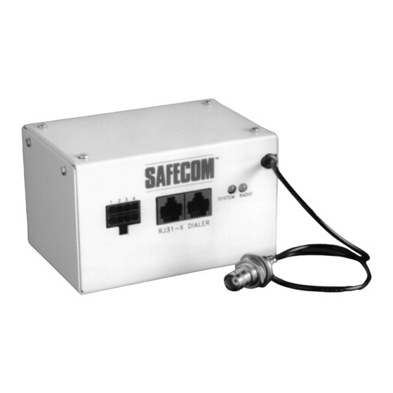
Figure 3: SC3100 Radio Communicator Antenna Each SC3100 Radio Communicator unit is shipped from Bosch Security Systems with a 20 in. (50.8 cm) antenna coaxial cable assembly to mount the antenna directly on the host alarm panel enclosure (as shown above). The unit is also shipped with a 2"... -
Page 20: Connecting Wires To The Sc3100
IT1500 Tester. Use the 2-inch x 2-inch antenna mounting L-bracket to attach the antenna to a beam or supporting structure. For remote antenna installations, Bosch Security Systems recommends using RG-58 for distances up to 15 ft. (4.2 m). RG-8 for distances up to 30 ft. (9.1 m). -
Page 21: System Initialization
SAFECOM SC9000 COMPUTER Figure 6: System Parameters • S/N: This number must match the CPU Serial Number listed on the label of the SAFECOM SC3100. • PID: This number must match the PID number on the label of the SAFECOM SC3100. -
Page 22: Figure 7: Programming Parameters
Dialer that the SC3100 will be communicating with dictate the selection for this entry. • Allow Dial Pause?: Y or N: Allow Dial Pause sets the amount of time that the SAFECOM SC3100 will tolerate no activity after a digit has been dialed before deciding that the Receiver ACK tone should be transmitted. - Page 23 26= 1400 Hz ACK Tone, 4+2 pulse type format 27= 1400 Hz ACK Tone, 4+2 pulse type format with parity. 28= 1400 Hz ACK Tone, FBI Superfast (DTMF) SC3100 Operation and Installation Guide © 2004 Bosch Security Systems Page 23 90026-201D Get other manuals https://www.bkmanuals.com...
-
Page 24: Establishing Communications With The Central Station Safecom Sc9000 Computer
Power On, a hardware component failure is possible. When the SC3100 system detects a hardware failure, the System Status LED on the SC3100 will illuminate SC3100 Operation and Installation Guide 90026-201D Page 24 © 2004 Bosch Security Systems Get other manuals https://www.bkmanuals.com... -
Page 25: Manual Initialization Of An Sc3100 Radio Communicator
Apply auxiliary power to the SC3100. Power On. This step will initiate a system startup. The SC3100 will behave exactly like a brand new unit. SC3100 Operation and Installation Guide © 2004 Bosch Security Systems Page 25 90026-201D Get other manuals https://www.bkmanuals.com... - Page 26 SC3100 System Initialization Notes: SC3100 Operation and Installation Guide 90026-201D Page 26 © 2004 Bosch Security Systems Get other manuals https://www.bkmanuals.com...
-
Page 27: Programming Worksheet Sc3100 Radio Communicator Account Setup
Enable Auto Fallback? (see this manual): Make Dial Tone? (see this manual): Allow Dial Pause? (see this manual): Digital Format (see this manual): Digital XLAT (see this manual): SC3100 Operation and Installation Guide © 2004 Bosch Security Systems Page 27 90026-201D Get other manuals https://www.bkmanuals.com... - Page 28 SC3100 Programming Worksheet Notes: SC3100 Operation and Installation Guide 90026-201D Page 28 © 2004 Bosch Security Systems Get other manuals https://www.bkmanuals.com...
-
Page 29: Limited Warranty
Product, provided it is returned in accordance with the terms of this warranty to the place of purchase. Repair, at the option of Bosch Security Systems, may include the replacement of parts, boards or other components with functionally equivalent reconditioned or new parts, boards or other components. - Page 30 SC3100 Notes SC3100 Operation and Installation Guide 90026-201D Page 30 © 2004 Bosch Security Systems Get other manuals https://www.bkmanuals.com...
- Page 31 SC3100 Notes SC3100 Operation and Installation Guide © 2004 Bosch Security Systems Page 31 90026-201D Get other manuals https://www.bkmanuals.com...
- Page 32 © 2004 Bosch Security Systems 90026-201D 03/04 130 Perinton Parkway, Fairport, NY 14450-9199 Operation and SC3100 Customer Service: (800) 289-0096 Technical Support: (888) 886-6189 Installation Guide Page 32 of 32 Get other manuals https://www.bkmanuals.com...