Advertisement
Quick Links
Advertisement

Related Manuals for Beko HNT 61210 X


Summary of Contents for Beko HNT 61210 X
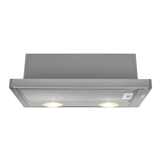
- Page 1 Hood User manual HNT 61210 X...
-
Page 2: Table Of Contents
INDEX RECOMMENDATIONS AND SUGGESTIONS ........................3 CHARACTERISTICS ................................6 INSTALLATION..................................7 USE ......................................9 MAINTENANCE ................................... 10... -
Page 3: Recommendations And Suggestions
RECOMMENDATIONS AND SUGGESTIONS The Instructions for Use apply to several versions of this appliance. Accordingly, you may find descriptions of individual features that do not apply to your specific appliance. INSTALLATION • The manufacturer will not be held liable for any damages resulting from incorrect or improper installation. - Page 4 • If the instructions for installation for the gas hob specify a greater distance specified above, this has to be taken into account. Regulations concerning the discharge of air have to be fulfilled. • Use only screws and small parts in support of the hood. Warning: Failure to install the screws or fixing device in accordance with these instructions may result in electrical hazards.
- Page 5 • “CAUTION: Accessible parts may become hot when used with cooking appliances.” MAINTENANCE • Switch off or unplug the appliance from the mains supply before carrying out any maintenance work. • Clean and/or replace the Filters after the specified time period (Fire hazard). •...
-
Page 6: Characteristics
CHARACTERISTICS Components Ref. Q.ty Product Components Hood Body, complete with: Controls, Light, Blower, Filters Directional Air Outlet grille Closing element Ref. Q.ty Installation Components Screws 4,2 x 44,4 Screws 4,2 x 12,7 Screws 2,9 x 12,7 Q.ty Documentation Instruction Manual... -
Page 7: Installation
INSTALLATION Drilling the Support surface and Fitting the Hood SCREW FITTING • The hood support surface must be 135 mm above the bottom surface of the wall units. • Drill the support with a ø 4,5 mm drill bit, using the drilling template provided. - Page 8 Connections DUCTED VERSION AIR EXHAUST SYSTEM When installing the ducted version, connect the hood to the chimney using either a flexible or rigid pipe ø120 mm, the choice of which is left to the installer. • Fix the pipe in position using sufficient pipe clamps ø...
-
Page 9: Use
Control panel M - V Light Switches the lighting system Light Switches the lighting system on and off. on and off. Motor Switches the extractor motor Motor Switches the extractor motor on and off. on and off. Speed Sets the operating speed of Speed Sets the operating speed of the extractor:... -
Page 10: Maintenance
MAINTENANCE Grease filters CLEANING METAL CASSETTE GREASE FILTERS • The filters must be cleaned every 2 months, or more frequently in case of particularly heavy use of the hood. Filters can be washed in a dishwasher. • Pull out the sliding suction panel. •... - Page 11 Lighting LIGHT REPLACEMENT 28 W halogen light. • Remove the metal grease filters. • Unscrew the bulbs and replace them with new ones having the same characteristics. • Replace the metal grease filters. Lamp Power (W) Socket Voltage (V) Dimension (mm) ILCOS Code HSGSB/C/UB-28-220/240-E14 220 –...
- Page 12 991.0504.458_ver1 - 170407 - D003655_00...