Table of Contents
Advertisement
Quick Links
Installation, Operation and Maintenance
INSTRUCTIONS MANUAL
HITACHI SPLIT-TYPE AIR CONDITIONERS
─
INVERTER DRIVEN
─
AIR-COOLED TYPE
IMPORTANT:
READ AND UNDERSTAND THIS
INSTRUCTION MANUAL BEFORE
USING THIS AIR CONDITIONER.
KEEP THIS MANUAL FOR FUTURE
REFERENCE.
Models :
Indoor Unit
RPS-90AN
─
─
Outdoor Unit
+
RAC-90JP
65MP3195
Advertisement
Table of Contents

Related Manuals for Hitachi RAC-90JP


Summary of Contents for Hitachi RAC-90JP
- Page 1 Models : Indoor Unit Outdoor Unit RPS-90AN RAC-90JP Installation, Operation and Maintenance INSTRUCTIONS MANUAL HITACHI SPLIT-TYPE AIR CONDITIONERS ─ ─ INVERTER DRIVEN ─ ─ AIR-COOLED TYPE IMPORTANT: READ AND UNDERSTAND THIS INSTRUCTION MANUAL BEFORE USING THIS AIR CONDITIONER. KEEP THIS MANUAL FOR FUTURE REFERENCE.
- Page 2 NOTE Useful information for this operation and/or maintenance. ● If you have any questions, contact your installer, dealer of HITACHI or our customer care. ● This manual gives you description and information on how to operate this air conditioning unit.
-
Page 3: Table Of Contents
— CONTENTS — Item Page Operation Instructions ..................1 PREPARATION Installation Location .................... 6 Installation Space ....................6 Foundation ......................8 Unit Check ......................8 INSTALLATION Anti-tumbler for Indoor Unit ................9 Anti-tumbler for Outdoor Unit ................10 REFRIGERANT AND DRAINAGE PIPING Preparations ....................... -
Page 4: Operation Instructions
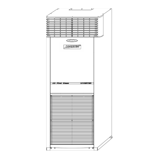
Operation Instructions Operation Instructions WARNING ◆ Name of Parts INDOOR UNIT Horizontal Louver Air Outlet Vertical Louver Front Cover Air Inlet Gas Refrigerant OUTDOOR UNIT Piping Liquid Refrigerant Air Inlet Piping Field and Control Wiring Power Supply Main Circuit Breaker Leakage Breaker Air Outlet - 1 -... - Page 5 Operation Instructions ◆ Precautions on Usage Don’t insert any material into the air Please use fuse/circuit breaker with proper amperage. inlet and air outlet. Never use metal or copper wire as a fuse to It may cause accidents and may injure avoid fault or occurrence of fire hazard.
- Page 6 Operation Instructions Operation Instructions ◆ Wired remote controller (RC-A01ET1) ● Parts inside the box (Please check) 1. Wired remote controller x1 (communication wire x1, length = 9m) 2. Accessory assembly (plug x2, screw x2, cable tie x2) CAUTION (For safety, please obey the following items) 1.
- Page 7 Operation Instructions Operation Instructions ● Installation of Remote Controller 1. Separate the base of the wired remote controller. Please follow the procedure: Use flat screwdriver to insert the groove and rotate lightly. Be careful, do not break the claws near the groove, if the claws are broken then wired remote controller will not easily fix on the base.
- Page 8 Operation Instructions ● Wiring 1. Method of connecting to air-conditioner: 1.1 Remove the front cover and electric box cover of the Indoor unit. 1.2 Connect the communication wire to the PCB of the Indoor unit (connector no: CN22) 1.3 Re-install the electric box cover and front cover, be careful don’t clip the wire. ●...
-
Page 9: Preparation
Preparation 1. Preparation 1.1 Installation Location (1) Required Material – Measure, Architectural Information Regarding Installation Location. (2) Confirm that the final installation location is provided with convenient piping and wiring work. (3) Check the total piping length and difference in height between indoor and outdoor unit, it should not exceed the following: Maximum Piping Length Difference in Height... - Page 10 Preparation Preparation ◆ Operation Space for Outdoor Unit Individual Outdoor Unit (2) In case of existence of (3) In case of existence of (1) In case of existence of obstruction in the back obstruction on the front obstruction on top and and by the side (open (open space in the back, in the back (open...
-
Page 11: Foundation
Preparation 1.3 Foundation (1) Check to ensure that the foundation is flat leveled and sufficiently strong. (2) Confirm elevation provision for the outdoor unit on a solid base with an iron frame or concrete curbs. Unit Leveled Installation (3) To obtain proper clearance beneath the either rooftop or on-the-ground installation, provide a gravel or concrete space around the outdoor unit air intake. -
Page 12: Installation
Installation Installation 2. Installation 2.1 Anti-tumbler for Indoor Unit (1) Be sure to secure the air conditioner with the anti-tumbler angle iron. (2) To keep the air conditioner from tumbling, fix it on the floor and the wall. Securing of the wall fixation angle iron ●... -
Page 13: Anti-Tumbler For Outdoor Unit
Installation 2.2 Anti-tumbler for Outdoor Unit (1) Use fix bolts as shown in the figure right to secure the unit on the base. (2) Apply enhanced installation to keep off seismic movements and typhoons. (3) Use cement base. Refer to figure below. Remark: The securing bolts are measured from 15mm in the base. -
Page 14: Refrigerant And Drainage Piping
Size : Ø 6.35mm Size : Ø 15.88mm Type : 1/4 Flare Nut Type : 5/8 Flare Nut RPS-90AN RAC-90JP Ø 20mm From (11~30m) Quantity : Quantity : (4) Confirm that the indoor unit piping direction and accessories is suitable. -
Page 15: Refrigerant Piping
Refrigerant and Drainage Piping Refrigerant and Drainage Piping 3.2 Refrigerant Piping (1) Check to ensure that the stop valves of outdoor unit have been closed. (2) Attach the connection pipes to the stop valves. (3) Remove the air inlet grill, filter, filter guide and lower front cover. (4) Connect the indoor and the outdoor unit with the specified refrigerant pipes. - Page 16 Refrigerant and Drainage Piping Refrigerant and Drainage Piping A. Outdoor Unit Below B. Outdoor Unit Above Field Piping Arrangement (Maximum piping length = 30m) 3.3 Drainage piping (1) The indoor drainage and the outdoor drainage shall be joined with adherent agents. (2) For assurance of normal drainage tubing operation, a water filler shall be given for a gradual adding of 1000cc of water from the right side of the air outlet to the evaporator while checking for leakage in the drainage.
-
Page 17: Evacuation And Refrigerant Charge
Evacuation and Refrigerant Charge Evacuation and Refrigerant Charge 4. Evacuation and Refrigerant Charge Tools and Instruments Vacuum Pump, High Pressure Compound Gauge, Low Pressure Compound Gauge, Refrigerant Cylinder with Sufficient R32A Refrigerant, Weighing Scale, Charging Hoses (Lead Pipes), Other General Piping Tools and Ratchet Wrenches. -
Page 18: Electrical Wiring
RPS-90AN 1 PHASE, 230V/60Hz 11.9A Outdoor Unit RAC-90JP 1 PHASE, 230V/60Hz 5.2 Main Power Wiring Procedures (1) If the phase is wrong, exchange two of the three wires connected from the main power source to the main terminals of the unit as indicated with the dotted lines, and then check the rotation direction of the phase sequence indicator once again. -
Page 19: Main Power Wiring Specification
Electrical Wiring 5.3 Main Power Wiring Specification Model RPS-90AN + RAC-90JP Nominal Cross-sectional Area Power Wire 5.5 mm (Or above UL 1015 AWG # 10) Connecting Wire 1.25 mm 5.4 Control Wiring Connect the control wires between the indoor unit terminals and the outdoor unit terminals according to the following to the wiring label. -
Page 20: Test Running
Test Running Test Running 6. Test Running 6.1 Final Installation Check Inspect the installation work according to all documents and drawings. Installation Work Check List shows the minimum check points. Installation Work Check List INSTALLATION WORK CHECK LIST 1. Is the unit solidly mounted and leveled? 2. -
Page 21: Safety And Control Device Setting
Test Running Test Running 6.4 Safety and Control Device Setting Model RPS-90AN + RAC-90JP For Compressor Auto Reset, Non-adjustable High Pressure Switch kg/cm Cut-out 4150 Cut-In kg/cm 3200 Discharge Gas Thermostat Cut-Out Cut-In Internal Thermostat for Outdoor Fan Motor Cut-Out... -
Page 22: Maintenance
(8) Tighten all wiring connections and access panels. 7.6 Replacement of Parts Replacement of parts should be performed by ordering from the HITACHI Parts List. The Form A HITACHI Recommended Spare Parts List is advisable. When replacement of parts becomes necessary, prepare the parts shown in the Form A Parts List. - Page 23 Maintenance Test Running and Maintenance Record POWER SUPPLY : Main Power: Phase, Control : Unit Compressor Model RPS - + RAC - Production No. CUSTOMER’S NAME : (PHONE NO. CUSTOMER’S ADDRESS: INSTALLED BY: DATE: START-UP BY: DATE: 1. Is the indoor air flow sufficient? 2.
- Page 24 No. 1A Binictican Drive Subic Bay Industrial Park Phase ll Subic Bay Freeport Zone Philippines TEL: (02 65MP3195-A1 Specifications in this manual are subject to change without prior notice, in order that HITACHI may bring the latest innovations to our customers.