Sanyo DSR-3706PA Instruction Manual
Digital video recorder with multiplexer function
Hide thumbs
Also See for DSR-3706PA:
- Manual for remote operation (43 pages) ,
- Quick operation manual (18 pages)

Related Manuals for Sanyo DSR-3706PA


Summary of Contents for Sanyo DSR-3706PA
- Page 1 INSTRUCTION MANUAL Digital Video Recorder with Multiplexer Function About this manual Before installing and using this unit, please read this manual carefully. Be sure to keep it handy for later reference. DSR-3706PA...
-
Page 2: Table Of Contents
Table of Contents Foreword Safety precautions ....... 3 These must be followed for safety reasons ..3 Follow the points outlined below for proper use . - Page 3 Table of Contents Recording area menu description... . . 43 b Verifying the capacity of the recording areas ..43 Changing the normal recording area and the alarm recording area ....44 Archive area full reset .
-
Page 4: Foreword
Please note: Your SANYO product is designed and manufactured with high quality materials and components which can be recycled and reused. This symbol means that electrical and electronic equipment, at their end-of-life, should be disposed of separately from your household waste. - Page 5 Safety precautions b Delivery and portability • Never move this unit while the power is turned on. • Remove the power cable from the outlet, confirm that the connection cable has been removed, and store in original packaging before delivering. Deliver using a method that causes the least amount of shock and/or damage to this unit.
-
Page 6: Follow The Points Outlined Below For Proper Use
Safety precautions Follow the points outlined below for proper use b Hard disk This unit is loaded with a hard disk drive. Stored data on this unit may be damaged/lost through hard-disk breakdowns caused by shock/vibration. Follow the items outlined below when placing, transporting, and operating this unit. Warning G This unit is designed to be positioned horizontally. - Page 7 This may cause the exterior to deteriorate or the paint to wear off. b Copyright information • This manual and software are copyrighted by Sanyo Electric Co., Ltd. • Brand and product names used in this manual are the trademarks or registered trademarks of their respective companies.
-
Page 8: Main Features
Main Features b This digital video recorder (DVR) can record video from surveillance cameras to its internal hard disk, and it can display the video on a screen split into six or four fields, both during recording, and playback. b Complete range of recording and playback functions •... -
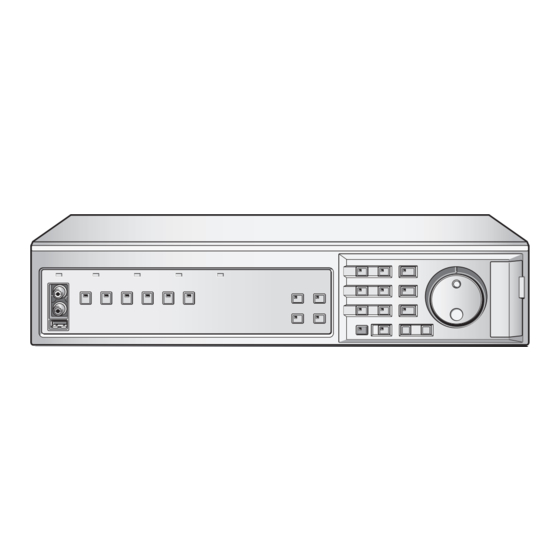
Page 9: Names And Functions Of Parts (Front Panel)
Names and functions of parts (front panel) DSR-3706PA Power indicator (POWER) On: The power cord at the rear panel of the DVR is inserted in the outlet. Off: The power cord on the rear panel of the DVR is not inserted in the outlet. - Page 10 Names and functions of parts (front panel) K L M Menu button and indicator (MENU) On: The menu is displayed. Off: The EXIT/OSD button is pressed. Exit/Operation screen display button and indicator (EXIT/OSD) On: Displaying the channel and operations information when switching from the menu screen, etc.
-
Page 11: Names And Functions Of Parts (Rear Panel)
If both are connected, the microphone input terminal will be enabled. 3 Video input terminal (Video IN) Connect SANYO protocol cameras (dome or zoom) or generic cameras to these terminals. (P70) ALARM IN SENSOR ALARM OUT... -
Page 12: Alarm And Rs-485 Connections
Names and functions of parts (rear panel) Alarm and RS-485 connections 1 Alarm input terminals (ALARM IN) Connecting a switch or security sensor etc. to the terminal of the DVR allows the detection of the intrusion of outsiders when doors etc. -
Page 13: Control Terminals (Control)
Names and functions of parts (rear panel) Control terminals (CONTROL) This DVR can be remotely controlled when a remote-control circuit (R1, R2, C) similar to that shown below is connected to the remote-control terminals. • Use a resistance of 1/10 ohms or more and with a D ranking (Precision within ±0.5%). •... -
Page 14: How To Use
Preparing for use Turn on the power of the DVR Connect the supplied power cable. The power indicator turns on, and the monitor displays the "PLEASE SET THE CLOCK !" message. The DVR performs playbacks or searches based on the recording date and time. -
Page 15: Operation Display
Preparing for use Operation display The operation display shows information necessary for operation, such as the date, time and video quality. The operation display can be hidden. 5 6 7 01-01-06 00:00:00 REC REPEAT EN A ALARM 0000 Date display 01-01-06 (day, month, year): Do not forget to set the date using the menu settings when turning the power on for the first time. -
Page 16: Viewing Live Video Using Various Multi Screens
Viewing live video using various multi screens Switching to another full-screen video Press the camera selection button (example 2, 6) of the desired camera. The video from Camera 2, then the video from Camera 6 are displayed. ☞ Refer to P20 for enlarging the images (zoom). How to use Enlarging an image (Plus screen display) -
Page 17: Automatic Screen Scrolling
Viewing live video using various multi screens Automatic screen scrolling A Automatic full-screen scrolling Press the SEQUENCE button. The live surveillance video scrolls through the cameras in the order of the camera numbers. To stop the automatic scrolling, press the SEQUENCE button once again. -
Page 18: Recording Video To The Hard Disk
Recording video to the hard disk The internal hard disk is automatically formatted with recording area, normal recording, recording conditions, etc. Before starting recording, verify the recordable duration for normal recording (List of recording rate and recording times: P83). The formatting can be modified using "Recording settings". -
Page 19: Viewing Recorded Video
Viewing recorded video This DVR can play video that has already been recorded or currently being recorded in the normal recording area (by normal or timer-controlled recording). Normal recording area (Hard disk recording areas) Playback • If the start point of the recording becomes unknown due to deleting video or resetting, then video playback will start from the earliest recording. -
Page 20: Changing The Playback Speed
Viewing recorded video Changing the playback speed The corresponding symbol ( ...) appears in the operation display area for each of these operations. Audio will not be played when changing the playback speed. A Fast-forward/Slow playback (Normal (Fast-forward) (Slow) playback) Turn the J-dial clockwise. -
Page 21: Enlarged Viewing
Viewing recorded video Enlarged viewing The zoom function is not available in multi-screen, plus screen mode or on the monitor connected to MON2 terminal. Press the ZOOM button. A zoom frame appears in the center of the screen. Live video can be magnified during surveillance. Images become coarser during zooming. -
Page 22: Searching For Recorded Video
Searching for recorded video Video stored in the normal recording area, alarm recording area or archive area can be located by searching and then played back. Use one of the five search methods to locate the required video. Press the SEARCH button: SEARCH The <SEARCH>... -
Page 23: A Alarm Search
Searching for recorded video Alarm search Press the SEARCH button during recording or live video. Turn the J-dial, select "ALARM SEARCH", and turn the S-dial clockwise. The <ALARM SEARCH> screen is displayed. The eight most recent alarm recordings are displayed. ☞... -
Page 24: C Date/Time Search
Searching for recorded video Date/time search Press the SEARCH button during recording or live video. Turn the J-dial, select "TIME/DATE SEARCH", and turn the S-dial clockwise. The cursor moves to "CHANNEL". ☞ Press the SEARCH button to cancel the search mode. -
Page 25: D Archive Area Search
Searching for recorded video Archive area search Plays back video stored in the archive area. Press the SEARCH button during recording or live video. Turn the J-dial, select "ARCHIVE AREA SEARCH", and turn the S-dial clockwise. The <ARCHIVE AREA SEARCH> screen is displayed. The eight most recent archive recordings are displayed in the order of archiving. - Page 26 Searching for recorded video Motion detection search (continued) Press the SEARCH button during recording or live video. Turn the J-dial, select "MOTION DETECTION SEARCH", and turn the S-dial clockwise. The <MOTION DETECTION SEARCH 1> screen appears. The "SEARCHING" starts blinking. ☞...
-
Page 27: Motion Sensor Settings Verification Using The Preview Screen
Searching for recorded video Motion detection search (continued) b Motion sensor settings verification using the preview screen <MOTION DETECTION SEARCH 2> SEARCH FROM : ALARM / CHANNEL : 4 START : 05-01-06 10:00 05-01-06 20:00 MOTION SENSOR -> PREVIEW -> VIEW ->... -
Page 28: Copying Recorded Video To Media
Copying recorded video to media Selected video stored in the normal recording area and the alarm recording area can be copied to various media (full screen). Images copied to a CompactFlash card can be directly printed on a printer. Copying video from the normal or alarm recording area to the archive area (P28) We recommend using this area to store video only for quick... -
Page 29: A Copying Video (Example: 10 Seconds) From The Normal Or Alarm Recording Area To The Archive Area
Copying recorded video to media Copying video (example: 10 seconds) from the normal or alarm recording area to the archive area Start playback from the normal or alarm recording area. Press the STILL button at the image to be copied. The image is paused. -
Page 30: B Copying Video (Example: 10 Seconds) From The Internal Hard Disk To The Cd-R/Rw Drive
Copying recorded video to media Copying video (example: 10 seconds) from the internal hard disk to the CD-R/RW drive Connect the optional CD-R/RW drive to the USB connector on the front or rear panel of the DVR. If the front and the rear USB terminal are connected simultaneously the front is given priority. -
Page 31: C Copying Video (Example: 10 Pictures) From The Internal Hard Disk To Media Such As A Compactflash Card
Copying recorded video to media Copying video (example: 10 pictures) from the internal hard disk to media such as a CompactFlash card Copy to a Microdrive is also possible, up to 2GB. Insert the card into the CompactFlash card slot. Refer to the names and functions of parts when inserting the card. -
Page 32: D Printing Images Directly From The Compactflash Card Or The Microdrive
• If "CF→PRINT" is selected, the time necessary to copy is about twice as long as (1MB per 30 seconds) when "COMPACT FLASH" is selected. • Use the SANYO DVP-P1 Digital Photo Printer. Operation is not guaranteed if using another printer. How to use Turn the J-dial to select HOW MANY "10", and then... -
Page 33: Compactflash Cards Or Cd-Rw Formats
CD-R/RW on a PC Copying video to a CompactFlash and a CD-R/RW creates the following folders and saves the images. With a CompactFlash 1st layer SANYO D DM M YY <WARNING> STORED DATA ON THE COMPACT FLASH WILL BE ERASED ! -
Page 34: How To Set
Main menu configuration The main menu consists of seven items, and can be displayed by pressing the MENU button. <MAIN MENU> 1.INITIAL SET -> 2.RECORD SET -> 3.GENERAL SET -> 4.SCREEN SET -> 5.POWER LOSS/USED TIME -> 6.INITIALIZATION LOG -> 7.COPY MENU SETTINGS ->... -
Page 35: Initial Settings
Initial settings Menu configuration b Displaying the initial settings screen Press the MENU button. The <MAIN MENU> screen is displayed. MENU <MAIN MENU> 1.INITIAL SET 2.RECORD SET 3.GENERAL SET 4.SCREEN SET Turn the S-dial clockwise, turn the J-dial to select the submenu and then turn the S-dial clockwise The <INITIAL SET>... -
Page 36: A Summer Time Setting
Initial settings Summer time setting Automatic switching from standard time to summer time can be set. Display the <LANGUAGE/LANGUE/SPRACHE/ IDIOMA> screen as explained in "Displaying the initial settings screen" (P34). MENU 1.INITIAL SET <INITIAL SET> 1.LANGUAGE/CLOCK SET <LANGUAGE/LANGUE/SPRACHE/IDIOMA> 01-01-2006 SUN 00:00:00 <SUMMER TIME SET>... -
Page 37: C Title Setting
Initial settings Title setting Titles for each camera can be up to 10 characters. Display the <TITLE SET> screen as explained in "Displaying the initial settings screen" (P34). The monitor shows live video, and the <TITLE SET> screen is displayed. MENU 1.INITIAL SET <INITIAL SET>... -
Page 38: E Time Period Setting
Initial settings Time period setting The time period setting allows for using different settings, such as automatic scrolling, masking, motion sensor detection settings for four periods of the day (for example: early morning, morning, daytime and evening). There are two timers (A and B) that can be set to control time periods as shown below, allowing for a wide variety of settings to suit every surveillance need. -
Page 39: Changing The Time Period Of Operations
Initial settings Time period setting (continued) Set automatic scrolling, masking or motion sensor for the time periods (A/B). The default setting for "SELECT TIME PERIOD" is A for all items. When the specified time comes, these operations will work in time period A, but more detailed settings are necessary. -
Page 40: Recording Settings
Recording settings Menu configuration b Displaying the recording settings screen b Displaying the recording settings screen Press the MENU button and use the J-dial to select "2. RECORD SET", and then turn the S-dial clockwise. The <RECORD SET> screen appears. MENU <MAIN MENU>... -
Page 41: A Easy Recording Menu Description
Recording settings Easy recording menu description The following two easy settings are available. ☞ RECORDING DURATION BASE (P41) <RECORDING DURATION BASE> RECORDING DURATION : -- DAYS TIMER RECORDING(DLY) : OFF START --:-- STOP --:-- PICTURE QUALITY : ENHANCED AUDIO RECORDING : OFF NUMBER OF CAMERAS REC RATE... -
Page 42: Recording Duration Base
Recording settings RECORDING DURATION BASE Setting the recording based on duration Display the <NORMAL REC EASY SET> screen as explained in "Displaying the recording settings screen" (P39). The <NORMAL REC EASY SET> screen appears. MENU 2.RECORD SET <RECORD SET> 1.NORMAL REC EASY SET <NORMAL REC EASY SET>... -
Page 43: Rec Rate Base
Recording settings REC RATE BASE Set the recording based on recording rate Display the <NORMAL REC EASY SET> screen as explained in "Displaying the recording settings screen" (P39). The <NORMAL REC EASY SET> screen appears. MENU 2.RECORD SET <RECORD SET> 1.NORMAL REC EASY SET <NORMAL REC EASY SET>... -
Page 44: B Recording Area Menu Description
Recording settings Recording area menu description This screen is used to verify the total capacity of the hard disk, and the recording capacity of the individual recording areas. The recording areas can be modified as needed. Modifying the recording areas will result in initializing the hard disk, and all recordings to be erased. -
Page 45: Changing The Normal Recording Area And The Alarm Recording Area
Recording settings Changing the normal recording area and the alarm recording area This operation will initialize the hard disk. Display the <RECORDING AREA SET> screen as explained in "Displaying the recording settings screen" (P39). MENU 2.RECORD SET <RECORD SET> 2.RECORDING AREA SET <RECORDING AREA SET>... -
Page 46: Archive Area Full Reset
Recording settings Archive area full reset The archive area cannot be automatically overwritten. Performing "AREA FULL RESET" will erase all images from the archive area. Display the <RECORDING AREA SET> screen as explained in "Displaying the recording settings screen" (P39). MENU 2.RECORD SET <RECORD SET>... -
Page 47: C Recording Conditions Menu Description
Recording settings Recording conditions menu description This menu is used to set whether to continue recording and automatically overwrite data, or stop recording without overwriting the data when the normal recording area and the alarm recording area of the hard disk become full. Selects the "OVERWRITE"... -
Page 48: Overwrite Setting For The Recording Areas
Recording settings Overwrite setting for the recording areas Display the <RECORDING CONDITIONS SET> screen as explained in "Displaying the recording settings screen" (P39). MENU 2.RECORD SET <RECORD SET> 3.RECORDING CONDITIONS SET <RECORDING CONDITIONS SET> NORMAL RECORDING AREA OVERWRITE ALARM RECORDING AREA OVERWRITE RECORDING DISK WARNING SERIES RECORDING... -
Page 49: Series Recording
Recording settings Setting series recording (continued) Display the <RECORDING CONDITIONS SET> screen as explained in "Displaying the recording settings screen" (P39). MENU 2.RECORD SET <RECORD SET> 3.RECORDING CONDITIONS SET <RECORDING CONDITIONS SET> NORMAL RECORDING AREA OVERWRITE ALARM RECORDING AREA OVERWRITE REMAINING DISK WARNING SERIES RECORDING AUTO DELETE... -
Page 50: D Normal Recording Area Menu Description
Recording settings Normal recording area menu description This menu is used to set the picture quality, audio recording and recording rate for the normal recording area. A program number can be selected at the programmed recording settings to use the recording rate set for that program. -
Page 51: E Programmed Recording Menu Description
Recording settings Programmed recording menu description This menu is used to set the desired cameras for each group (P-1, P-2, P-3 and P-4) for programmed recording. For each group, cameras are selected to enable or disable recording from them, and their individual recording rates are also set here. -
Page 52: F Timer Setting Menu Description
Recording settings Timer setting menu description This menu is used to set the start and end times for timer-controlled recording. The following timer functions are available: <TIMER SET> WEEK START STOP PROGRAM --:-- --:-- 12.5 FPS OFF --:-- --:-- 12.5 FPS OFF --:-- --:-- 12.5 FPS OFF... -
Page 53: Day Of The Week Timer-Controlled Recording (Same Time, Same Recording Rate Every Week For The Specified Day)
Recording settings Day of the week timer-controlled recording (same time, same recording rate every week for the specified day) Display the <TIMER SET> screen as explained in "Displaying the recording settings screen", and then turn the S-dial clockwise. (P39) The "SUN" field starts blinking. MENU 2.RECORD SET <RECORD SET>... -
Page 54: Overlapping Timer-Controlled Recording
Recording settings Overlapping timer-controlled recording Display the <TIMER SET> screen as explained in "Displaying the recording settings screen". (P39) MENU 2.RECORD SET <RECORD SET> 6.TIMER SET WEEK START --:-- --:-- --:-- --:-- --:-- --:-- --:-- --:-- ***** Set the timer-controlled recording. Example: MON 10:30 **:** ** * **** FPS *** WED **:** 20:30 OFF... -
Page 55: External Timer-Controlled (Alarm) Recording
Recording settings External timer-controlled (alarm) recording Connect an external timer device to the EXT TIMER IN terminal on the rear panel (Figure 1). Display the <TIMER SET> screen as explained in "Displaying the recording settings screen". (P39) MENU 2.RECORD SET <RECORD SET>... -
Page 56: G Alarm Recording Settings Menu Description
Recording settings Alarm recording settings menu description The following settings can be performed under the alarm recording settings. <ALARM REC MODE SET> ALARM RECORDING : OFF PICTURE QUALITY : ENHANCED AUDIO RECORDING : OFF ALARM INTERLEAVE : ONLY REC RATE: 12.5FPS, DURATION: 20SEC PRE-ALARM RECORDING : ***... -
Page 57: Alarm Recording Settings
Recording settings Alarm recording settings Display the <ALARM REC MODE SET> screen as explained in "Displaying the recording settings screen", and then turn the S-dial clockwise. (P39) The "OFF" field of ALARM RECORDING starts blinking. MENU 2.RECORD SET <RECORD SET> 7.ALARM REC MODE SET <ALARM REC MODE SET>... -
Page 58: Pre-Alarm Recording Settings
Recording settings Pre-alarm recording settings Display the <ALARM REC MODE SET> screen as explained in "Displaying the recording settings screen", and then turn the S-dial clockwise. (P39) The "OFF" field of ALARM RECORDING starts blinking. MENU 2.RECORD SET <RECORD SET> 7.ALARM REC MODE SET <ALARM REC MODE SET>... -
Page 59: Motion Sensor Screen Description
Recording settings Motion sensor screen description Use this screen for motion sensor setting on a live video screen to detect moving objects such as intruders, and generate alarms. The motion sensor detects movement based on intensity-changes on the screen. It is necessary to use sensor settings that are appropriate for both the location of the sensor and for the observed objects. -
Page 60: Motion Sensor Setting
Recording settings Motion sensor setting Set "TIME PERIOD A" and "TIME PERIOD B" using <TIME PERIOD SET> (P37). Display the <ALARM REC MODE SET> screen as explained in "Displaying the recording settings screen", and then turn the S-dial clockwise. (P39) The "OFF"... -
Page 61: H Alarm Operation Settings Menu Description
Recording settings Alarm operation settings menu description This menu is used to extend the duration of the alarm recording and to set the display method when an alarm occurs. <ALARM OPERATION SET> ALARM RETRIGGER : OFF MAIN MON. DISPLAY : FULL ALARM PRIORITY : LAST MON.2 DISPLAY... -
Page 62: Alarm Operation Settings
Recording settings Alarm operation settings Display the <ALARM OPERATION SET> screen as explained in "Displaying the recording settings screen", and then turn the S-dial clockwise. (P39) The "OFF" indicator of ALARM RETRIGGER starts blinking. MENU 2.RECORD SET <RECORD SET> 8.ALARM OPERATION SET <ALARM OPERATION SET>... -
Page 63: General Settings
General settings Menu configuration b Displaying the general settings screen Press the MENU button and use the J-dial to select "3. GENERAL SET", and then turn the S-dial clockwise. The <GENERAL SET> screen appears. MENU <MAIN MENU> 1.INITIAL SET 2.RECORD SET 3.GENERAL SET 4.SCREEN SET Turn the J-dial, select the desired... -
Page 64: A Data Display Settings/Video Loss Settings
General settings Data display settings/VIDEO LOSS settings These settings are used to control the operating display area of the monitor, to display the date, time and other information. Normally all indicators are displayed, but they can be hidden, if needed. "VIDEO LOSS"... -
Page 65: B Buzzer Settings
General settings Buzzer settings These settings are used to generate a warning buzzer when the hard disk is full and at alarm events. Display the <BUZZER SET> screen as explained in "Displaying the general settings screen", and then turn the S-dial clockwise. (P62) The "OFF"... -
Page 66: C Security Lock Menu Description
General settings Security lock menu description This menu is used to set passwords and to limit access to the DVR. There are two passwords, one for the administrator, and one for the user. <SECURITY LOCK SET> LEVEL PASSWORD(4-8) USE ADMIN -------- USER --------... -
Page 67: Activating The Security Lock
General settings Activating the security lock When the administrator and user settings are complete, activate the security lock. Press the SHUTTLE HOLD button for about 3 seconds while live video is on the screen. The LOCK indicator on the front panel turns on and a buzzer sounds to indicate the activation of the security lock. -
Page 68: List Of Permitted Operations After Setting The Passwords
General settings b List of permitted operations after setting the passwords If both the ADMIN and USER are "ON": • If the ADMIN password is entered, all operations will be permitted. • If no password is entered, all operations will be denied. 1 ADMIN 2 USER Settings... -
Page 69: D Hard Disk Settings Menu Description
We recommend using the expansion hard disk provided by SANYO. Operation is not guaranteed if a hard disk other than SANYO's recommended type is used for capacity expansion. • The hard disks must be initialized, upon installing an expansion disk. -
Page 70: E Network Settings
General settings Network settings Connecting the DVR to the network Refer to the Network connection terminals (LAN). (P11) Display the <NETWORK SET> screen as explained in "Displaying the general settings screen", and then turn the S-dial clockwise. (P62) The "OFF" field NETWORK CONTROL starts blinking. MENU 3. -
Page 71: Settings
General settings RS-485 settings Connect the RS-485 terminal on the rear panel of the DVR with the system controller (Figure 1). Display the <RS-485 SET> screen as explained in "Displaying the general settings screen", and then turn the S-dial clockwise. (P62) The DATA SPEED "19200"... -
Page 72: Screen Settings
Screen settings Menu configuration b Displaying the screen settings Press the MENU button and use the J-dial to select "4. SCREEN SET", and then turn the S-dial clockwise. The <SCREEN SET> screen appears. MENU <MAIN MENU> 1.INITIAL SET 2.RECORD SET 3.GENERAL SET 4.SCREEN SET 5.POWER LOSS/USED TIME... -
Page 73: A Changing The Multi-Screen Sequence
Screen settings Changing the multi-screen position Display the <SCREEN SET> screen as explained in "Displaying the screen settings", and then turn the S-dial clockwise. (P71) The "NORMAL" field of 1. MULTI SCREEN starts blinking. MENU 4.SCREEN SET 1.MULTI SCREEN QUAD POSITION SET MULTI 6 POSITION SET 2.SEQUENCE SEQUENCE SET... -
Page 74: Automatic Scrolling Of Live Video Of The Main Monitor And The Monitor 2 At Identical Intervals (Example: 5 Seconds)
Screen settings Automatic scrolling of live video of the main monitor and the monitor 2 at identical intervals (example: 5 seconds) Display the <SCREEN SET> screen as explained in "Displaying the screen settings" (P71). MENU 4.SCREEN SET 1.MULTI SCREEN QUAD POSITION SET MULTI 6 POSITION SET 2.SEQUENCE SEQUENCE SET... -
Page 75: Automatic Sequence Of Live Video Of The Main Monitor (Full-Screen) At Individual Intervals, And Of The Monitor 2 At Identical Intervals (Example: 3 Seconds)
Screen settings Automatic sequence of live video of the main monitor (full-screen) at individual intervals, and of the monitor 2 at identical intervals (example: 3 seconds) Display the <SCREEN SET> screen as explained in "Displaying the screen settings" (P71). Turn the J-dial, select "2. SEQUENCE", and then turn the S-dial clockwise. -
Page 76: C Masking Specific Camera Images
Screen settings Masking specific camera images Set TIME PERIOD A and TIME PERIOD B using <TIME PERIOD SET> (P37). Select "TIME PERIOD A" or "TIME PERIOD B" for "MASK" under "SELECT TIME PERIOD". The example uses "TIME PERIOD A". TIME PERIOD TIME PERIOD A 06:00 11:30 13:30 18:00 TIME PERIOD B 06:00 08:00 14:30 20:00 SELECT TIME PERIOD... -
Page 77: D Adjusting Color Tones Of The Live Video
Screen settings Adjusting color tones of the live video Display the <SCREEN SET> screen as explained in "Displaying the screen settings" (P71). MENU 4.SCREEN SET 1.MULTI SCREEN QUAD POSITION SET MULTI 6 POSITION SET 2.SEQUENCE SEQUENCE SET MAIN/MON.2 MONITOR SET -> 3.MASK MASK SET 4.COLOR LEVEL SET... -
Page 78: Power Loss Information/Used Time
Power loss information/Used time Power loss/Used time menu description <POWER LOSS/USED TIME> POWER LOSS #000 ----- --:-- ----- --:-- ----- --:-- ----- --:-- USED TIME DISK1 USE : DISK2 USE : POWER F/W : M 2.00-00 / S 2.00-00 Power loss Displays the number of power outages. -
Page 79: Initialization Log
Initialization log Initialization log menu description <INITIALIZATION LOG> DATE TIME AREA ----- --:-- ------ ----- --:-- ------ ----- --:-- ------ ----- --:-- ------ ----- --:-- ------ ----- --:-- ------ ----- --:-- ------ ----- --:-- ------ DATE/TIME Displays the date and time of the initialization. Displays the eight most recent items in the initialization log. -
Page 80: Menu Copy
Menu copy Menu copy screen description Save the set menu on the CompactFrash (CF) card and load the same menu onto a different DVR of the same model. It is possible to control several units using the same menu. <COPY MENU SETTINGS> DVR TYPE VER. -
Page 81: Load Menu Content Saved To The Cf Card Onto Other Dvrs Of The Same Model
Menu copy Load menu content saved to the CF card onto other DVRs of the same model. Press the MENU button in order to display the <COPY MENU SETTINGS> screen and load the menu content onto other DVRs of the same model. MENU <COPY MENU SETTINGS>... -
Page 82: Other
EXIT/OSD Other b Communication protocol It is recommended that the exclusive controller is used for operation as a protocol unique to our company (SANYO protocol) is used for this DVR. Consult the service center regarding the exclusive controller. REV PLAY/... -
Page 83: Specifications
Specifications Signal method PAL signal standard Compression method Video: M-JPEG, Audio: WAVE Number of pixels 720 x 288 Recording type Field record Recording quality 5 stage [BASIC/NORMAL/ENHANCED/ FINE/SUPER FINE] Recording rate 27 levels (50 to 0.033FPS) Recording area Normal recording area/alarm recording area/archive area Zoom 2x digital zoom is possible using the... -
Page 84: List Of Recording Rate And Recording Times
List of recording rate and recording times The recording time on this DVR are adjusted automatically when the recording rate and the recording quality have been altered. The list below displays the recording rate and quality when recording images within the hard disk normal recording area of this DVR. - Page 85 List of recording rate and recording times b When recording using an 500GB hard disk (when 99% of the area is utilized) Recording rate BASIC (fields/second) 15kB 151 (H) 16.67 12.5 8.333 6.25 1209 1512 4.167 1814 3.571 2117 3.125 2419 2.778 2722...
-
Page 86: List Of Record Rate Setting/Pre-Alarm Recording Times
List of record rate setting/pre-alarm recording times b Recording rate setting Normal recording Recording rate (FPS) (Note 1) (Note 3) 16.67 12.5 8.333 6.25 4.167 3.571 3.125 2.778 2.273 1.923 1.667 1.563 1.471 1.316 1.190 1.087 0.333 0.25 0.05 0.033 (Note 1) Rate setting will be limited when the mirroring function is turned "ON"... -
Page 87: Push-Lock Terminal Specifications
Push-lock terminal specifications Input/output terminals <ALARM IN> [0 voltage contact] <SENSOR ALARM OUT> [Open collector/1kΩ, Low Level active (max. 25 mA)] <Control terminals> Remote input (Refer to P12) [2 wire voltage control type] (REMOTE R1, R2) Date adjustment input [Zero voltage contact] (CLOCK IN) Clock adjustment output [Open collector/1kΩ, Low Level... - Page 88 SANYO Electric Co., Ltd. 1AC6P1P3018-- L8HBM/XE (0206KP)